

Page 1

ICs for Audio Common Use
AN5278
4.8 W × 1 (18 V, 8 Ω) Power Amplifier with
Volume and Tone Control
■ Overview
The AN5278 is a monolithic integrated circuit designed
for 4.8 W × 1 channel OTL (18 V, 8 Ω) output audio power
amplifier suitable for TV application.
■ Features
• Few external components :
• No boucherot cells (output C, R)
• No bootstrap capacitors
• Built-in DC mute of input pin during power-OFF
• Operating voltage range 12 V to 26 V (18 V typ.)
19.9±0.1
18.3±0.25
φ2.65±0.1
φ3.3±0.1
0.1±0.05
8.4±0.25
5.8±0.25
1.5±0.25
5.6±0.25
6.3 7.1
±0.3 ±0.25
15.0
Unit : mm
3.75±0.25
9
8
7
6
5
4
3
2
1
0.5
±0.1
1.7±0.25
2.54
+0.1
1.2
–0.05
0.45
±0.25
22.3±0.3
■ Applications
• TV
■ Block Diagram
±0.25
1.7
HSIP009-P-0000
Pre
amp.
10 kΩ
AC
mute
10 kΩ
300 Ω
Tone Volume
1
2
In
3
LF
4
Tone
Vol.
5
RF
6
NF
7
8
GND
Out
DC
mute
9
CC
V
1
Page 2

AN5278 ICs for Audio Common Use
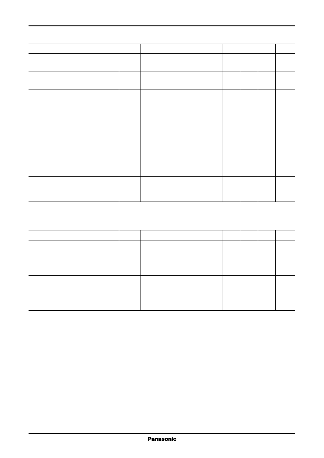
■ Pin Descriptions
Pin No. Description
1 Sound input
2 Low frequency input
3 Tone control
4 Volume control
5 Ripple filter
6 Negative feedback
7 GND
8 Sound output
9V
■ Absolute Maximum Ratings
Supply voltage
Supply current I
Power dissipation
Operating ambient temperature
Storage temperature
Note) *1:Ta = 25 °C except operating ambient temperature and storage temperature.
*2: Without input signal, VCC is up to 35 V.
*3: Power dissipation of the package at Ta = 70 °C.
CC
Parameter Symbol Rating Unit
2
*
3
*
1
*
1
*
V
CC
CC
P
D
T
opr
T
stg
35.0 V
2A
1.6 W
−20 to +70 °C
−55 to +150 °C
■ Recommended Operating Range
Parameter Symbol Range Unit
Supply voltage V
2
CC
12 to 26 V
Page 3
ICs for Audio Common Use AN5278
■ Electrical Characteristics at VCC = 18 V, RL = 8 Ω, f = 1 kHz, Vol. = 5.0 V, Tone = 2.5 V, Ta = 25 °C
Parameter Symbol Conditions Min Typ Max Unit
Quiescent current I
Voltage gain G
Total harmonic distortion THD V
Max. output power P
Max. output attenuation Att
Tone variable range 1 ∆GTC1 f = 15 kHz, VO = 1 V[rms] 7 9 dB
Tone variable range 2 ∆GTC2 f = 15 kHz, VO = 1 V[rms] −11 −9dB
No input signal 20 27 48 mA
CQ
Measure VCC current
VO = 1 V[rms] 27 30 33 dB
V
GV = 20 log (VO/VIN)
= 1 V[rms] 0.4 1.0 %
O
BPF : 400 Hz to 30 kHz
THD = 10 %, PO = V
Omax
maxVO
= 1 V[rms] −66 −69 dB
2
/R
O
L
4.3 4.8 W
Vol. = max. → min.
Att
= 20 log
max
[VO (Vol. = min.) / VO (Vol. = max.)]
∆GTC = 20 log
[VO (Tone = 5.0 V) / VO (Tone = 2.5 V)]
∆GTC = 20 log
[VO (Tone = 0 V) / VO (Tone = 2.5 V)]
• Design reference data
Note) The characteristic values below are theoretical values for designing and not guaranteed.
Parameter Symbol Conditions Min Typ Max Unit
Input dynamic range DR
INVVOL
= 1 V 4.5 V[rms]
vary VIN until output THD = 1 %
Output DC bias V
No input signal 7.9 8.3 8.7 V
ODC
Measure Pin8 DC
Max. output power 1 P
Max. output power 2 P
THD = 10 %, VCC = 18.4 V 5 W
Omax1
PO = V
THD = 10 %, VCC = 26 V 9 W
Omax2
PO = V
2
/R
O
L
2
/R
O
L
3
Page 4

AN5278 ICs for Audio Common Use
■ Application Circuit Example
330 Ω
1
In
10 µF33 µFInput
0.01 µF
Line out
10 kΩ
6.2 kΩ
2
LF
Tone
5 V
3
Tone
4
Vol.
100 µF
5 V
5
RF
Volume
100 Ω
6
NF
47 µF
7
GND
10 µF
470 µF
330 Ω
■ Usage Notes
1) External heatsink is needed when used. External heatsink should be fixed to the chassis.
2) Fin of the IC can be connected to GND.
3) Please prevent output to VCC short, output to GND short and load short to GND.
4) The temperature protection circuit will operate at T
protection circuit would automatically be deactivated and resume normal operation.
around 150 °C. However, if the temperature decreases, the
j
8
Out
Speaker
8 Ω
Micom
1 Audio det.
9
CC
V
1000 µF
18 V
4
Page 5

ICs for Audio Common Use AN5278
■ Technical Information
1.Characteristic Curve Chart
• HSIP009-P-0000 Package power dissipation
PD T
a
11
4
10.4
10
9
8
(W)
7
D
6
5
3
4.14
4
2
3.36
Power dissipation P
3
1
2.5
2
1
0.0
0 25 150
50 7570 100 125
6.65
2.63
2.15
1.6
1 No heat sink
2 5.5 × 5.0 cm
3 7.5 × 7.5 cm
4 Infinity heat sink
Ambient temperature Ta (°C)
P
<
max
(t = 1 mm)
(t = 1 mm)
− T
T
jmax
a
R
th
2
A1 board
2
A1 board
• ASO
(A)
e
I
2
1
0.5
0.2
0.1
0.05
0.02
0.01
Area of Safe Operation
12
5 10 20 50 10035
t = 100 ms
VCB (V)
5
Page 6

AN5278 ICs for Audio Common Use
■ Technical Information (continued)
2.Application Note
1) Gain setting and frequency response
The gain is fixed to be 30 dB by internal resistors. The frequency response is flat for the values of R1 = 6.2 kΩ, and
C2 = 0.01 µF, between pins 1 and 2 (other conditions : tone control voltage is set at 2.5 V, and volume control voltage
is set at 5 V).
Gain
6.2 kΩ
R1
2
LF
300 Ω
Rf
C2
0.01 µF
6
NF
10 µF
10 kΩ
8
Out
1
In
10 µF
V
IN
The gain can be reduced by inserting a resistor Rf in series with the electrolytic capacitor at Pin6.
Voltage gain = 20 log [10 kΩ/(Rf + 300 Ω)]
30 dB
Frequency
RL = 8 Ω
Bass boost can be easily implemented by inserting a series connection of RC between Pin8 (output) and Pin6 (NF).
Example : Rb = 12 kΩ, Cb = 0.022 µF
6
NF
10 kΩ
8
Out
Cb Rb
RL = 8 Ω
300 Ω
Rf
6
Page 7

ICs for Audio Common Use AN5278
■ Technical Information (continued)
2.Application Note (continued)
2) Tone characteristics
When the tone control voltage (VT, at Pin3) is changed from 2.5 V to 5 V, the high frequency gain is increased
gradually up by a max. of 9 dB. When V
gradually down by a max. of −11 dB.
By increasing the value of the capacitor at Pin2, the treble cut can be further decreased.
is changed from 2.5 V to 0 V, the high frequency gain is decreased
T
Tone = 5 V
+9 dB
30 dB
Tone = 2.5 V
Gain (dB)
−11 dB
Tone = 0 V
115
Frequency (kHz)
3) Volume characteristic
The volume characteristic is logarithmic type. When the volume control voltage (VV, at Pin4) is 5 V, the gain is at
max. (30 dB) ; that is, there is no attenuation. When V
is 0 V, the gain is at its minimum ; that is, there is max. attenuation, −69 dB.
V
V
is decreased, the gain is decreased at the same time. When
V
0
Tone = 2.5 V
Attenuation (dB)
−69
0123
45
Voltage (V)
4) Dynamic range
The AN5278 has been designed, specially to have as large an input dynamic range as possible. The input D-range
is about 4.5 V[rms], or 12.7 V[p-p] (conditions of measurement : V
= 18 V, adjust the gain downwards by
CC
decreasing the volume control voltage).
7
Page 8

AN5278 ICs for Audio Common Use
■ Technical Information (continued)
2.Application Note (continued)
5) Internal AC mute pulse (during power ON/OFF)
The start-up response of the AN5278 is designed to be as smooth as possible. During power ON and OFF, the AC
mute circuit turn on momentarily. The input signal and any external noise interference are being mute. The output
DC level follows the rise and fall time of RF pin.
Condition : VCC = 18 V, CRF = 100 µF, CNF = 10 µF, C
V
CC
Pin9
V
RF
Pin5
3.6 V
Output
Pin8
= 1000 µF.
VCC
3.6 V
3.2 V
2.4 V
2.8 V
Internal line
mute pulse
Line out
8
310 ms
660 ms
590 ms
100 ms
Page 9

ICs for Audio Common Use AN5278
■ Technical Information (continued)
2.Application Note (continued)
6) Internal DC mute pulse (during power OFF)
During power OFF, the decay response of the RF pin is being made use of internally, to generate an internal DC
mute pulse. The output DC level is made to fall quickly. As the output level falls, any transient noise that happens
prior to the input pin is effectively cut off from the IC. The residual electric charge in the large output capacitor (at
Pin8) is discharged into the IC internal path. By this manner, at the next start-up, the output will start from almost
0 V, and reduce the occurrence of shock noise.
Condition : VCC = 18 V, CRF = 100 µF, CNF = 10 µF, C
= 1000 µF.
VCC
Output
Pin8
Internal
DC mute
pulse
300 ms
7) Shock noise precaution
During power ON, to reduce the occurence of Shock noise, please be careful when selecting suitable capacitor
values for RF (Pin5) and NF (Pin6).
Recommendation : −
1. NF = 10 µF
* : Due to small NF capacitor, the low frequency cut-off is about 50 Hz.
2. NF = 22 µF
* : Due to larger RF capacitor, the start-up time is longer, about 1 second.
*
RF = 100 µF to 330 µF
*
RF = 220 µF to 330 µF
9
 Loading...