

Page 1
■ Overview
The AN5138NK is an integrated circuit designed for
video-IF and audio-IF processing circuits, in color TV and
VCR.
■ Features
•
By adopting built-in VCO PLL-type video-detector circuit, the high preformance IC-detector system can be
realized for sound multiplex and tele-text broadcasting.
•
Quadrature sound FM detector built-in.
•
Frequency characteristics compensation pin (Pin20)
VCR-switch pin (Pin5)
•
Sound-output level-adjustment pin (Pin25)
1
ICs for TV
AN5138NK
Video IF Amplifier, PLL Detector, AGC, AFC, SIF IC for Color TV
1
2
3
4
5
6
7
8
9
10
11
12
13
14
19
18
17
16
15
20
21
22
23
24
25
26
27
28
26.7±0.3
8.4±0.3
10.16±0.25
3 to 15˚
0.3
+ 0.1
– 0.05
4.8±0.25
1.05±0.25
3.05±0.25
1.778
0.5±0.1
0.9±0.25
Unit : mm
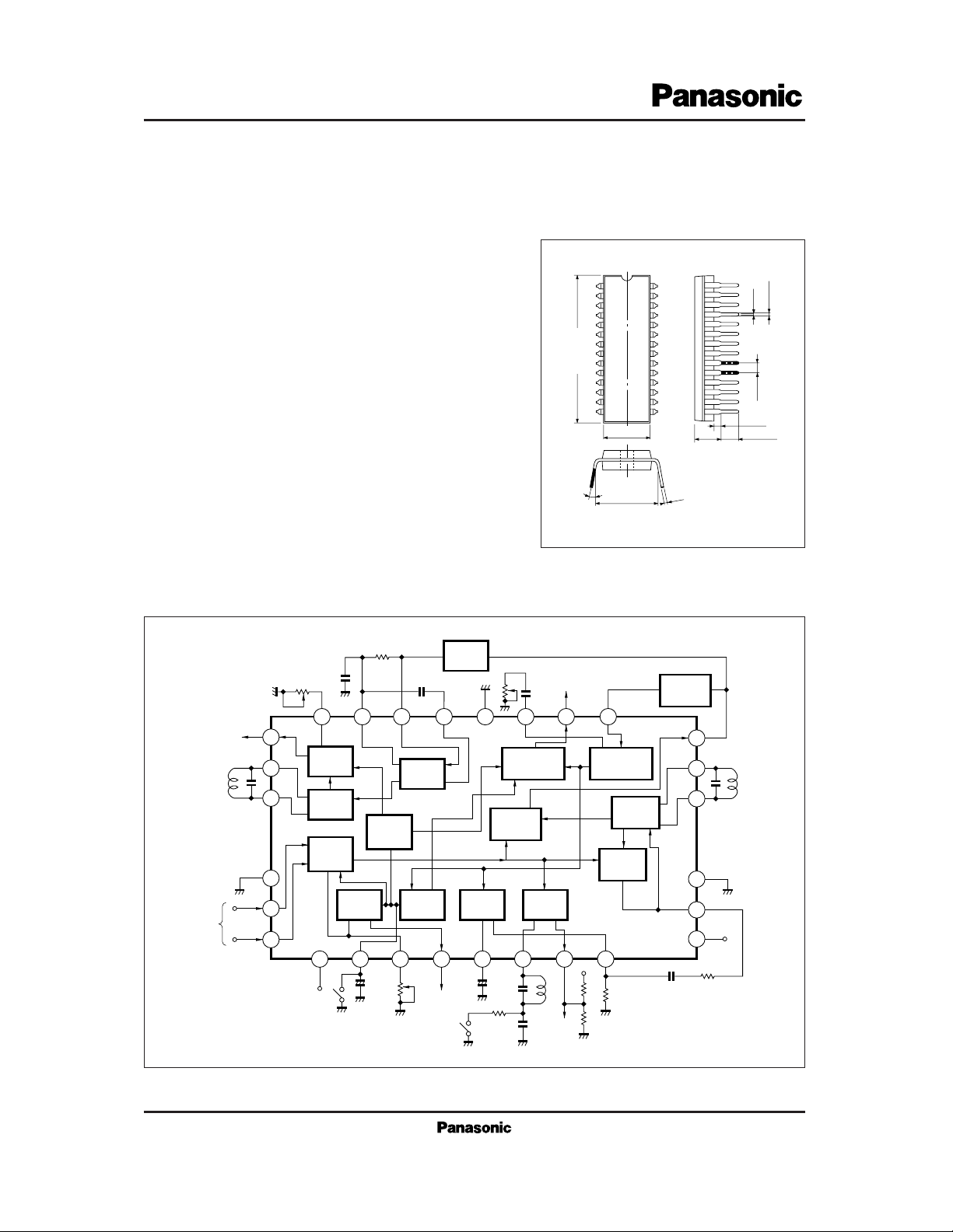
28-Pin Shrunk DIL Plastic Package
■ Block Diagram
SIF
VIF
Amp.
IF
AGC
RF
AGC
Delay
Adj.
Filter
RF
AGC
Out.
Lock
Det.
AFC
SW
Video
Det.
+
–
Video Output
Noise
Inverter
AFC
AFC
Out.
SIF
Trap
17
Video
Inverter
16
15
VCO
APC
Det.
1110987654
14
13
CC
V
12
VCC
Audio Level Adj.
Audio
Output
26
27
28
25 24 23 22 21 20 19 18
Level
Adj.
FM
Det.
VTR
SIF
SW
Amp.
1
RF
AGC
VTR SW
IF
+
AGC
–
Filter
2
3
VCC
IF
Input
Page 2
2
ICs for TV
AN5138NK
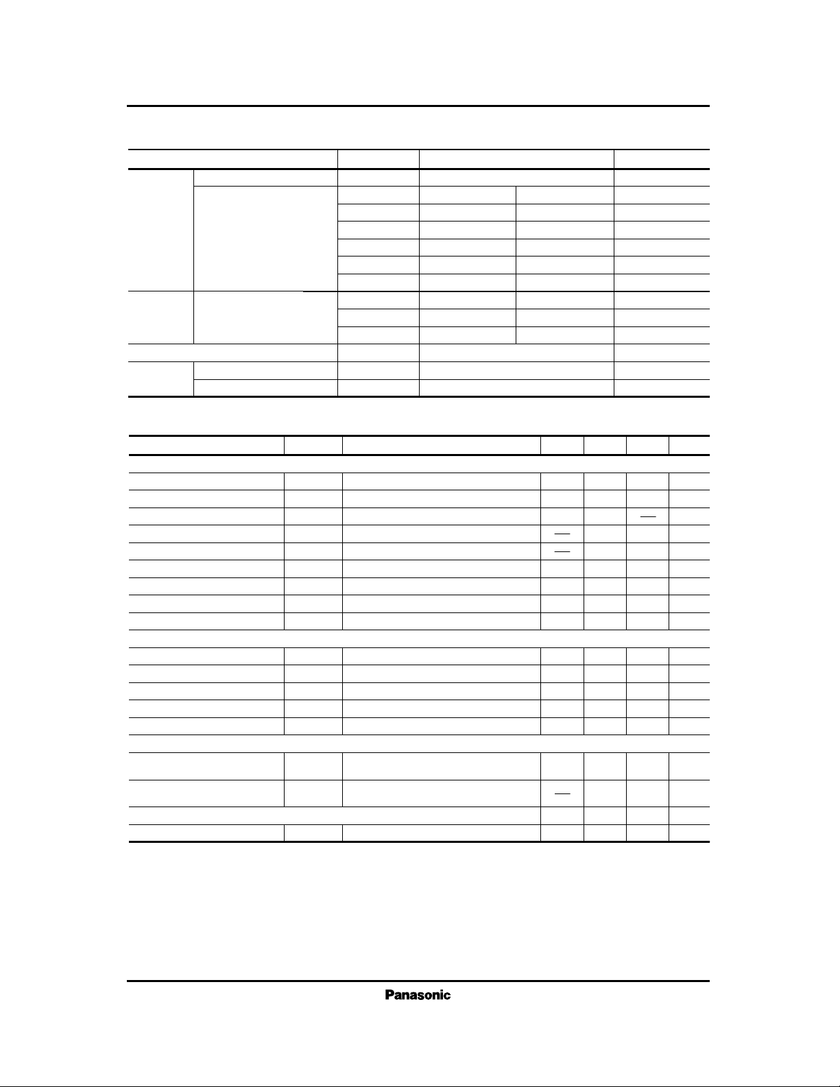
Parameter Symbol Rating Unit
V
CC
V
5-1, 14, 21
V
6-1, 14, 21
V
7-1, 14, 21
V
10-1, 14, 21
I
17
I
19
P
D
T
opr
T
stg
Circuit Voltage
Circuit Current
Supply Voltage
Operating Ambient Temperature
Power Dissipation (Ta=70˚C)
Storage Temperature
Voltage
Current
Temperature
13.8
1,300
–20 to + 70
–55 to + 150
V
mW
˚C
˚C
V
mA
V
V
V
mA
V
4, 12-1, 14, 21
0
V
4, 12-1, 14, 21
0
V
4, 12-1, 14, 21
0
V
4, 12-1, 14, 21
0
–7 + 0.5
–7 + 0.5
V
18-1, 14, 21
V
25-1, 14, 21
I
26
V
V
4, 12-1, 14, 21
0
V
8.0 0
mA
–5 + 0.5
■ Absolute Maximum Ratings (Ta=25˚C)
f= 58.75MHz, Vi= 80dBµ, m= 87.5% 1.9 2.2 2.5 V
P-P
50 70 90 mA
V
O
I4 + I
12
S (IN)
V1 (max.)
DG
G
RFAGC
VO= –3dB
Video detector output
Input sensitivity
Max. allowable input
49
103
5.5
40
53
108
2
6.5
44
57
6
7.5
48
dBµ
dBµ
%
MHz
dB
Parameter minCondition typ max UnitSymbol
IF Amplifier · Detection · AGC · AFC Circuit
Differential gain
Differential phase
Frequency characteristics
RF AGC gain
AFC phase det. sensitivity
AFC center voltage
VCO · APC Circuit
VCO control sensitivity
APC pull-in range (1)
APC pull-in range (2)
SIF Circuit
Circuit current
DP
fc
µ
V
10
β
f
APC (1)
f
APC (2)
f =58.75MHz, Vi= 80dBµ, m= 87.5%
f =58.75MHz, Vi= 80dBµ, m= 87.5%
f =10kHz, Vi=10mV
R
L
= 68kΩ//82kΩ
RL= 68kΩ//82kΩ
V
13
= 2V
2 5 deg
30 45 60
mV/kH
z
4.2 6.5 8.2 V
0.8 1.5 2.5 MHz
3 4.5 6
kH
z/mV
+ 0.85 +1.5 + 2.5 MHz
–3.5 – 2.5 –1.6 MHz
VCO max. variable range (1)
VCO max. variable range (2)
Total detector output
Input limiting voltage
DC Characteristics
∆f
V (1)
∆f
V (2)
V
O
V
i (lim)
VO= –3dB
V13= 3V
f
o
= 4.5MHz, fm= 400Hz
∆f= ±25kHz, Vi=100dBµ
f
o
= 4.5MHz, fm= 400Hz
∆f= ±25kHz, Vi=100dBµ
–3.4 – 2.4 –1.4 MHz
490 620 950 mV
rms
42 47 dBµ
■ Electrical Characteristics (VCC=12V, Ta=25˚C)
Page 3

3
ICs for TV
AN5138NK
TUNER
Level
Adj.
FM
Det.
VIF
Amp.
SIF
Amp.
VTR
SW
RF
AGC
IF
AGC
Lock
Det.
AFC
Video
Det.
VCO
APC
Det.
Noise
Inverter
Video
Inverter
SAW
Filter
220Ω
12µF
8.2µF
0.022µF
0.047µF
470Ω
820Ω
Audio
Output
5kB
5.1kΩ
4.5MHz
Filter
10kB
120pF
Video
Output
4.5MHz Trap
3.9kΩ
V
CC
(12V)
12pF
TLII58705
(58.75MHz)
GND
(VCO)
33µF4.7µF
0.01µF
0.47µF
+
–
+
–
+
–
+–
47Ω
560Ω
VCC
68kΩ
82kΩ
3.3µF
+
(VCO)
TLI
67321
20pF
100pF
56pF
1µF
3.3kΩ
18kΩ
5.6kΩ
AFC
SW
0.01µF
+
–
3.3µF
0.47µF0.01µF
10kB
4.7µH
0.68µH 820Ω
0.01µF
0.01µF
0.33µH
0.68µH
4.7µH
0.01µF
12pF
82Ω
820Ω
680Ω
5.6Ω
18Ω
0.001µF
5.6kΩ
22µH
680
Ω
4.5MHz
Discriminator
or
+–
33µF
TLS63318
68pF
GND
(VIF
Amp.)
AN5138NK
AFC AGC
1
3
2
4567891011
25 24 23 22 21 20 19 18
28
27
26 17
16
15
14
13
12
GND
27
28
V
CC
(12V)
■ Application Circuit
 Loading...