

Page 1
1 Introduction
This application note describes the implementation of the STM32 firmware library for the dSPIN
stepper motor control product (L6470). It provides a guide on how to use the library for final
application development.
The L6470 is a fully integrated microstepping motor driver with embedded motion engine and SPI
communication interface. A low R
supports different operating modes including a 128-microstep resolution. It is based on digital
control core surrounded with a number of different peripherals and protections. Chip operating
mode, motion profiles, and all the other parameters are memorized in an embedded set of
registers. Communication with the IC is done through an integrated 5 MHz SPI periphery in
determined data format according to the documentation. See the L6470 datasheet for more details
about registers, application commands, etc. The firmware library speeds up the application
development process and saves time consumed by register constant definitions and command
routine implementation in the microcontroller source code.
AN3980
Application note
STM32™ firmware library for dSPIN L6470
DMOS power stage is also a part of the IC. The chip
DSON
Firmware library main features
■
Designed for the STM32F1xx microcontroller family
■
STEVAL-PCC009V2 + STM32 value line Discovery demonstration boards supported with library
configuration (dspin.h) and development tools project files
■
Easy portability due to ANSI C standard compliance
– Only HAL (“Hardware Abstraction Layer”) routines should be modified when used with
another platform
– Simple portability to STM8™ families thanks to similar HAL routines for peripherals - SPI,
GPIOs, etc.
■
Library contains project folders (files) for development tools:
– IAR™ - EWARM v5
J-Link for STEVAL-PCC009V2
ST-Link for STM32 VL Discovery
– IAR - EWARM v6
J-Link for STEVAL-PCC009V2
– KEIL - µVision
ULINK2
ULINK Pro for STEVAL-PCC009V2
ST-Link for STM32 VL Discovery
– Raisonance - RIDE v7
®
v4.03, v4.20
®
for STEVAL-PCC009V2
R-Link for STEVAL-PCC009V2
November 2011 Doc ID 022200 Rev 1 1/18
www.st.com
Page 2

AN3980 Contents
Contents
1 Introduction . . . . . . . . . . . . . . . . . . . . . . . . . . . . . . . . . . . . . . . . . . . . . . . . 1
2 Library file structure . . . . . . . . . . . . . . . . . . . . . . . . . . . . . . . . . . . . . . . . . 4
3 Demonstration board electrical connection . . . . . . . . . . . . . . . . . . . . . . 6
4 dSPIN.h file content . . . . . . . . . . . . . . . . . . . . . . . . . . . . . . . . . . . . . . . . . 7
4.1 Demonstration board related signal assignments . . . . . . . . . . . . . . . . . . . 7
4.2 dSPIN Init structure definition . . . . . . . . . . . . . . . . . . . . . . . . . . . . . . . . . . . 9
4.3 Register options / mask definition (enumerated types) . . . . . . . . . . . . . . . 9
4.4 L6470 register addresses . . . . . . . . . . . . . . . . . . . . . . . . . . . . . . . . . . . . . 10
4.5 L6470 command set definition . . . . . . . . . . . . . . . . . . . . . . . . . . . . . . . . . 11
4.6 Macros definition . . . . . . . . . . . . . . . . . . . . . . . . . . . . . . . . . . . . . . . . . . . 11
5 dSPIN.c file content . . . . . . . . . . . . . . . . . . . . . . . . . . . . . . . . . . . . . . . . . 13
6 main.c file content . . . . . . . . . . . . . . . . . . . . . . . . . . . . . . . . . . . . . . . . . . 14
Appendix A Demonstration board images . . . . . . . . . . . . . . . . . . . . . . . . . . . . . . 15
References. . . . . . . . . . . . . . . . . . . . . . . . . . . . . . . . . . . . . . . . . . . . . . . . . . . . . . . . . 17
Revision history . . . . . . . . . . . . . . . . . . . . . . . . . . . . . . . . . . . . . . . . . . . . . . . . . . . . 17
Doc ID 022200 Rev 1 2/18
Page 3
List of figures AN3980
List of figures
Figure 1. Firmware library folder structure. . . . . . . . . . . . . . . . . . . . . . . . . . . . . . . . . . . . . . . . . . . . . . 4
Figure 2. Firmware library file list. . . . . . . . . . . . . . . . . . . . . . . . . . . . . . . . . . . . . . . . . . . . . . . . . . . . . 5
Figure 3. Demonstration board selection . . . . . . . . . . . . . . . . . . . . . . . . . . . . . . . . . . . . . . . . . . . . . . . 7
Figure 4. Demonstration board signal assignment . . . . . . . . . . . . . . . . . . . . . . . . . . . . . . . . . . . . . . . 8
Figure 5. L6470 registers structure type definition. . . . . . . . . . . . . . . . . . . . . . . . . . . . . . . . . . . . . . . . 9
Figure 6. Step select parameter definition for “Step Mode” register . . . . . . . . . . . . . . . . . . . . . . . . . . 9
Figure 7. Configuration register mask definition . . . . . . . . . . . . . . . . . . . . . . . . . . . . . . . . . . . . . . . . 10
Figure 8. Register addresses. . . . . . . . . . . . . . . . . . . . . . . . . . . . . . . . . . . . . . . . . . . . . . . . . . . . . . . 10
Figure 9. L6470 command set type definition . . . . . . . . . . . . . . . . . . . . . . . . . . . . . . . . . . . . . . . . . . 11
Figure 10. List of defined macros. . . . . . . . . . . . . . . . . . . . . . . . . . . . . . . . . . . . . . . . . . . . . . . . . . . . . 12
Figure 11. Demonstration board STEVAL-PCC009V2 . . . . . . . . . . . . . . . . . . . . . . . . . . . . . . . . . . . . 15
Figure 12. Demonstration board STM32F100 value line Discovery kit . . . . . . . . . . . . . . . . . . . . . . . . 15
Figure 13. L6470 demonstration board (EVAL6470) . . . . . . . . . . . . . . . . . . . . . . . . . . . . . . . . . . . . . . 16
3/18 Doc ID 022200 Rev 1
Page 4

AN3980 Library file structure
2 Library file structure
Firmware implementation is split between the following files:
● dspin.c
– Microcontroller peripherals initialization
– dSPIN application commands implementation
– Library support functions implementation
● dspin.h
– Function prototypes for implemented commands and support functions
– Register value (options) definition
– Register mask definition
– Macros for selected function parameter conversions
– Demonstration board related definitions - GPIO signals and peripherals
assignment
● main.c
– Example of library usage - system configuration / function calls
● Other microcontroller configuration files, such as
– clock.c, -.h, stm32f10x_conf.h (peripherals configuration), stm32f10x_it.c, -.h
(interrupt routines) and standard library for GPIO and SPI
Firmware is available for download in compressed zip format. By decompressing the archive
the following folder structure is created on a drive:
Figure 1. Firmware library folder structure
The “Libraries” folder contains microcontroller related files like peripheral source/header
files, startup file, etc.
Doc ID 022200 Rev 1 4/18
Page 5

Library file structure AN3980
The “Project” folder contains demonstration board related subfolders. dSPIN library source
and header files and other subfolders with project files for different development tools
appear in each of the demonstration board subfolders. A list of the source/header files can
be seen in Figure 2:
Figure 2. Firmware library file list
5/18 Doc ID 022200 Rev 1
Page 6
AN3980 Demonstration board electrical connection
3 Demonstration board electrical connection
The firmware library supports two demonstration boards:
1. STEVAL-PCC009V2 universal USB to serial bus interface
2. STM32F100 value line Discovery kit
In the case of STEVAL-PCC009V2, the connection of the L6470 demonstration board is
simple. It is only necessary to use a 10-wire flat cable connection line inserted into J1 on
STEVAL-PCC009V2 and J10 on the L6470 demonstration board. The signals are assigned
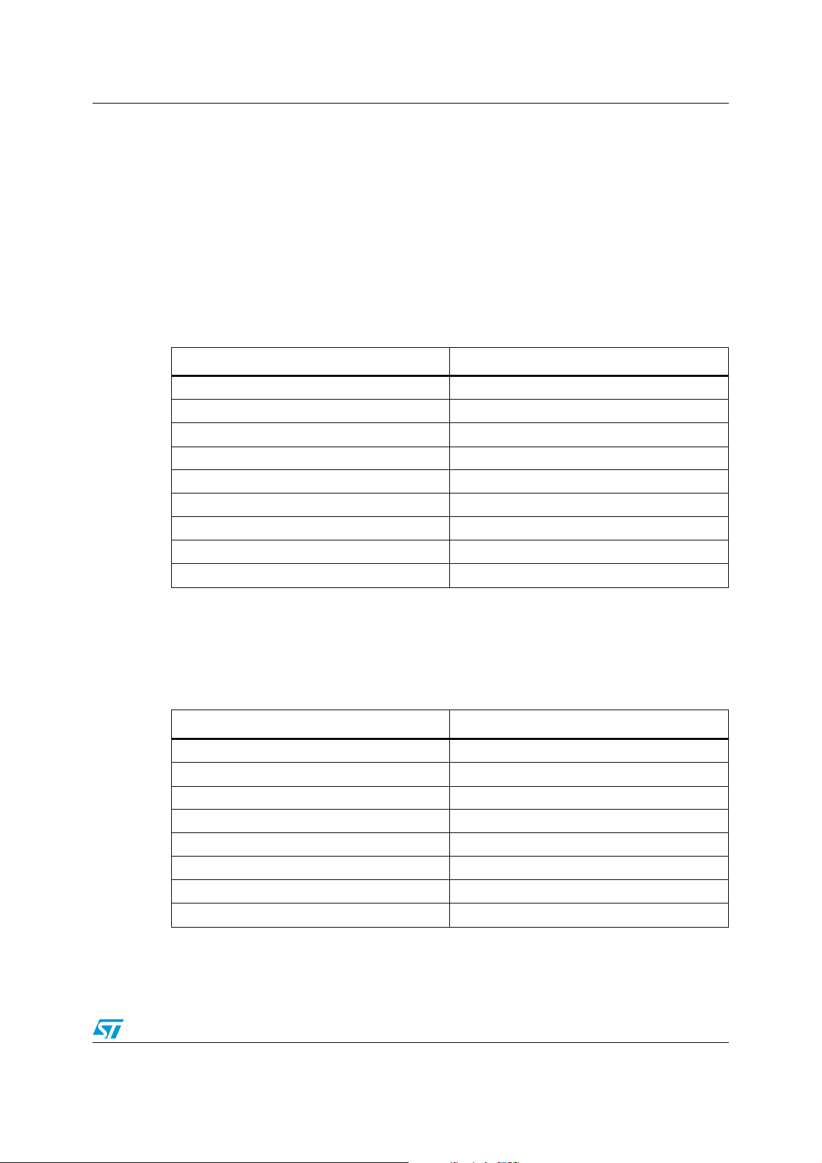
according to the appropriate section in the dSPIN.h file, see Table 1 :
Table 1. Microcontroller signal assignment for STEVAL-PCC009V2
L6470 demonstration board signal Microcontroller periphery
SPI Clock PB 13
SPI MOSI PB 15
SPI MISO PB 14
SPI nSS PB 12
BUSY PB 10
FLAG PB 11
PWM 1 PB 0
PWM 2 PB 1
STEVAL-PCC009V2 Power LED PC 4
Microcontroller peripherals for the STM32F100 value line Discovery kit connection have
been selected according to Table 2. The user is free to modify the assignment according to
their needs. The condition for correct functionality is consistency between physical
connection and dSPIN.h file content.
Table 2. Microcontroller signal assignment for STM32F100 value line Discovery kit
L6470 demonstration board signal Microcontroller periphery
SPI Clock PA 5
SPI MOSI PA 7
SPI MISO PA 6
SPI nSS PA 4
BUSY PC 4
FLAG PC 5
PWM 1 PA 1
PWM 2 PB 0
Doc ID 022200 Rev 1 6/18
Page 7

dSPIN.h file content AN3980
4 dSPIN.h file content
The dSPIN.h file contains the following:
● Demonstration board related signal assignments
● Structure definition for L6470 register initialization
● Register options / mask definition (enumerated types)
● L6470 register addresses (enumerated types)
● L6470 command set definition (enumerated types)
● Macro definition - used for function input parameter conversions
● List of function prototypes which are implemented in the dSPIN.c file.
4.1 Demonstration board related signal assignments
Demonstration board type must be defined prior to the signal assignment definition.
Therefore, one of the following lines should appear at the beginning of the dSPIN.h file:
Figure 3. Demonstration board selection
It is recommended to keep both in the code and comment the one which does not
correspond to the requested configuration.
7/18 Doc ID 022200 Rev 1
Page 8

AN3980 dSPIN.h file content
In Figure 4 it is possible to see how the signals are assigned depending on the
demonstration board type:
Figure 4. Demonstration board signal assignment
The second demonstration board option, STM32 value line Discovery, is implemented in
a similar way.
Doc ID 022200 Rev 1 8/18
Page 9

dSPIN.h file content AN3980
4.2 dSPIN Init structure definition
To configure all L6470 registers a dedicated structure type has been defined:
Figure 5. L6470 registers structure type definition
Typically, a variable is created in the main program loop and filled with requested register
parameters. Then, the appropriate function call
(dSPIN_Registers_Set(&dSPIN_RegsStruct)) can program all registers as requested by the
user.
4.3 Register options / mask definition (enumerated types)
As L6470 consists of 25 registers, and many of them include multiple parameter settings,
the complete code to cover all the definitions is large. The following lists are just selected
examples and the others can be found directly in the header file.
9/18 Doc ID 022200 Rev 1
Page 10

AN3980 dSPIN.h file content
Figure 6. Step select parameters definition for “Step Mode” register
Figure 7. Configuration register mask definition
4.4 L6470 register addresses
To allow access to L6470 registers, the following register address definition has been
created.
Doc ID 022200 Rev 1 10/18
Page 11

dSPIN.h file content AN3980
Figure 8. Register addresses
11/18 Doc ID 022200 Rev 1
Page 12

AN3980 dSPIN.h file content
4.5 L6470 command set definition
dSPIN motion and other types of commands are coded with numeric (single byte) constants.
For transparent code implementation, the following type definition has been created:
Figure 9. L6470 command set type definition
4.6 Macros definition
Some of the L6470 commands use input parameters which are proportional to a real
number. For this reason there is a need to recalculate (convert) the requested option
parameter in real numeric format to the function parameter in integer format. To make it user
friendly and allow usage of input parameters in real numeric format, macros for parameter
conversion have been implemented.
For example, the “Run” command supposes to get a speed parameter in unsigned fixed
point 0.28 number format. In this case, the “Speed_Steps_to_Par(speed)” macro can be
used to convert real speed (in steps per second) to the parameter of the “Run” command.
Doc ID 022200 Rev 1 12/18
Page 13

dSPIN.h file content AN3980
Figure 10. List of defined macros
13/18 Doc ID 022200 Rev 1
Page 14

AN3980 dSPIN.c file content
5 dSPIN.c file content
dSPIN.c is the library source file. It contains all the L6470 commands and the
implementation of other support functions.
It starts with the dSPIN_Peripherals_Init function which configures all the required
microcontroller peripherals (GPIOs, SPI) and it is called at the beginning of the main
program loop. The function considers signal assignments made in the dSPIN.h file.
The dSPIN_Regs_Struct_Reset function fills all the structure fields with default values.
The dSPIN_Registers_Set function programs all parameters into L6470 internal registers.
It uses pointer-to-structure as the input parameter, so the structure must be filled properly in
advance of this function call.
The dSPIN.c file contains all the dSPIN commands and the implementation of other support
functions. The code is well commented, please refer directly to the file for more details.
Doc ID 022200 Rev 1 14/18
Page 15

main.c file content AN3980
6 main.c file content
The main.c file starts with the system clock configuration in order to switch from internal RC
oscillator to external crystal circuit. It sets SYSCLK frequency to 24 MHz.
Then, the above mentioned dSPIN_Peripherals_Init function is processed.
The dSPIN_Regs_Struct_Reset function is called to fill all dSPIN_RegsStruct structure
fields with default values. As a next step, the majority of the dSPIN_RegsStruct fields are
modified either directly or with the help of the macros already described (see Section 4).
L6470 internal registers are then programmed by the dSPIN_Registers_Set function.
The rest of the main.c file code demonstrates how to use the library functions.
15/18 Doc ID 022200 Rev 1
Page 16

AN3980 Demonstration boards images
Appendix A Demonstration boards images
Figure 11. Demonstration board STEVAL-PCC009V2
Figure 12. Demonstration board STM32F100 value line Discovery kit
Doc ID 022200 Rev 1 16/18
Page 17

Demonstration boards images AN3980
Figure 13. L6470 demonstration board (EVAL6470)
17/18 Doc ID 022200 Rev 1
Page 18

AN3980 References
References
1. L6470 datasheet
2. AN3103 application note
3. STM32F100RB datasheet
4. STM32F103RB datasheet
5. RM0041 - STM32F100 reference manual
6. RM0008 - STM32F103 reference manual
7. STEVAL-PCC009V2 databrief
8. UM0919 user manual
Revision history
Table 3. Document revision history
Date Revision Changes
22-Nov-2011 1 Initial release.
Doc ID 022200 Rev 1 18/18
Page 19

AN3980
y
Please Read Carefully:
Informatio n in this document is provided solely in connection with ST products. STMicroelectronics NV and its subsidiaries (“ST”) reserve the
right to make changes, corrections, modifications or improvements, to this document, and the products and services described herein at an
time, without notice.
All ST products are sold pursuant to ST’s terms and conditions of sale.
Purchasers are solely responsible for the choice, selection and use of the ST products and services described herein, and ST assumes no
liability whatsoever relating to the choice, selection or use of the ST products and services described herein.
No license, express or implied, by estoppel or otherwise, to any intellectual property rights is granted under this document. If any part of this
document refers to any third party products or services it shall not be deemed a license grant by ST for the use of such third party products
or services, or any intellectual property contained therein or consid ered as a warranty covering the use in any manner whatsoever of such
third party products or services or any intellectual property contained therein.
UNLESS OTHERWISE SET FORTH IN ST’S TERMS AND CONDITIONS OF SALE ST DISCLAIMS ANY EXPRESS OR IMPLIED
WARRANTY WITH RESPECT TO THE USE AND/OR SALE OF ST PRODUCTS INCLUDING WITHOUT LIMITATION IMPLIED
WARRANTIES OF MERCHANTABILITY, FITNESS FOR A PARTICULAR PURPOSE (AND THEIR EQUIVALENTS UNDER THE LAWS
OF ANY JURISDICTION), OR INFRINGEMENT OF ANY PATENT, COPYRIGHT OR OTHER INTELLECTUAL PROPERTY RIGHT.
UNLESS EXPRESSLY APPROVED IN WRITING BY TWO AUTHORIZED ST REPRESENTATIVES, ST PRODUCTS ARE NOT
RECOMMENDED, AUTHORIZED OR WARRANTED FOR USE IN MILITARY, AIR CRAFT, SPACE, LIFE SAVING, OR LIFE SUSTAINING
APPLICATIONS, NOR IN PRODUCTS OR SYSTEMS WHERE FAILURE OR MALFUNCTION MAY RESULT IN PERSONAL INJURY,
DEATH, OR SEVERE PROPERTY OR ENVIRONMENTAL DAMAGE. ST PRODUCTS WHICH ARE NOT SPECIFIED AS "AUTOMOTIVE
GRADE" MAY ONLY BE USED IN AUTOMOTIVE APPLICATIONS AT USER’S OWN RISK.
Resale of ST products with provisions different from the statements and/or technical features set forth in this document shall immediately void
any warranty granted by ST for the ST product or service described herein and shall not create or extend in any manner whatsoever, any
liability of ST.
ST and the ST logo a re trademarks or registered trademarks of ST in various countries.
Information in this document supersedes and replaces all information previously supplied.
The ST logo is a registered trademark of STMicroelectronics. All other names are the property of their respective owners.
© 2011 STMicroelectronics - All rights reserved
STMicroelectronics group of companies
Australia - Belgium - Brazil - Canada - China - Czech Republic - Finland - France - Germany - Hong Kong - India - Israel - Italy - Japan -
Malaysia - Malta - Morocco - Philippines - Singapore - Spain - Sweden - Switzerland - United Kingdom - United States of America
www.st.com
Doc ID 022200 Rev 1 18/18
 Loading...