

Page 1

AN-1154
APPLICATION NOTE
dp
dQ
DEAD ZONE
BLEED CURRENT P US HE S THE
CHARGE PUMP O UT OF DEAD ZONE
10729-001
One Technology Way • P. O. Box 9106 • Norwood, MA 02062-9106, U.S.A. • Tel: 781.329.4700 • Fax: 781.461.3113 • www.analog.com
Optimizing Phase Noise and Spur Performance of the ADF4157 and ADF4158 PLLs
Using Constant Negative Bleed
by Robert Brennan and Dawid Powazynski
INTRODUCTION
The phase noise (PN) and integer boundary spur (IBS)
performance of the ADF4157 and the ADF4158 can be
improved by activating a constant negative bleed current. The
biggest improvement is achieved at frequencies at, or close to,
integer multiples of the phase frequency detector (PFD)
frequency. It is more visible for loop bandwidths greater than
60 kHz; however, it is recommended to use constant negative
bleed for all PLL loop bandwidths.
Constant negative bleed current works by adding a constant
offset to the charge pump (equivalent to a phase offset in
the PLL loop). This has the effect of linearizing the charge
pump by moving away from the nonlinear area near the origin
(sometimes referred to as the charge pump dead zone). Figure 1
illustrates this phenomenon.
Figure 1. The Effect of Bleed Current on Charge Pump
Without this constant current offset, sigma-delta quantization
(dQ) noise can fold back in-band and cause excessive noise or
spurs. This aliasing of sigma-delta noise in-band only happens
for high resolution sigma-delta modulators (equivalent to high
value of modulus) as used on the ADF4157 and ADF4158.
These parts require activation of a constant negative bleed
current to achieve optimal phase noise and spur performance.
This current is not needed for other Fractional-N PLLs with
lower value of modulus or Integer-N PLLs.
The constant negative bleed on the ADF4157 and ADF4158 is
activated by setting bits DB[24:23] in Register 4 to 0b11.
THE EFFECT OF BLEED CURRENT ON PHASE NOISE AND SPURS
The use of a constant negative bleed only improves phase noise
and integer boundary spurs for a certain range of charge pump
currents (I
can degrade. This phenomenon was measured for two PFD
frequencies, 12.5 MHz and 25 MHz. Each PFD frequency was
tested near two consecutive integer channels. The loop filter
configuration for each PFD frequency is show in the Appendix.
). For some values of ICP, phase noise and spurs
CP
HOW MEASUREMENTS WERE RECORDED
The measurements were recorded on an EV-ADF4157SD1Z
evaluation board. The loop filter was modified for each PFD
frequency.
1. The loop was locked at 5800.001 MHz using a PFD
frequency of 25 MHz.
2. The charge pump current was set to the minimum value
(0.31 mA).
3. Negative bleed was disabled.
4. The phase noise at a 5 kHz offset and the integer boundary
spur at 1 kHz were recorded.
5. Negative bleed was enabled.
6. The phase noise at a 5 kHz offset and the integer boundary
spur at 1 kHz were recorded.
7. Step 3 to Step 6 were repeated for every charge pump
current setting up to 5 mA.
8. Step 2 to Step 7 were repeated with the loop locked at
5825.001 MHz.
9. The loop filter was modified for a PFD frequency of
12.5 MHz, the loop was locked at 5800.001 MHz using a
PFD frequency of 12.5 MHz. Step 2 to Step 8 were
repeated.
Rev. 0 | Page 1 of 8
Page 2

AN-1154 Application Note
TABLE OF CONTENTS
Introduction ...................................................................................... 1
The Effect of Bleed Current on Phase Noise and Spurs .............. 1
How Measurements Were Recorded .............................................. 1
Revision History ............................................................................... 2
REVISION HISTORY
5/12—Revision 0: Initial Version
Results .................................................................................................3
Analysis of Results .............................................................................4
Conclusion..........................................................................................4
Appendix ............................................................................................5
Rev. 0 | Page 2 of 8
Page 3
Application Note AN-1154
0
PN (dBc/Hz) ; IBS (dBc)
0
PN (dBc/Hz) ; IBS (dBc)
0
PN (dBc/Hz) ; IBS (dBc)
0
PN (dBc/Hz) ; IBS (dBc)
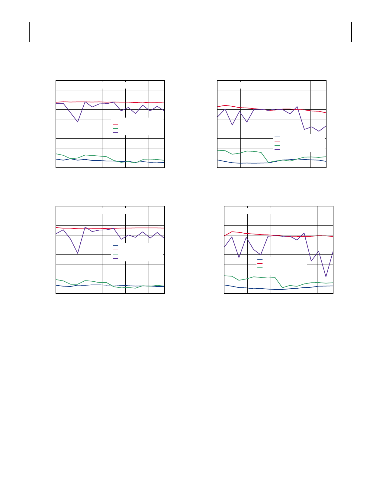
RE S U LT S
PFD Frequency = 25 MHz
Output frequency = 5800.001 MHz
RF
= 5800.001MHz; PFD = 25MHz
–10
–20
–30
–40
–50
–60
–70
–80
–90
0.31 1.31 2.31 3.31 4.31
OUT
CHARGE PUMP CURRENT (mA)
Figure 2. Phase Noise and IBS at 5800.001 MHz with
a PFD Frequency = 25 MHz
Output frequency = 5825.001 MHz
PN AT 5kHz; BLE E D OFF
IBS; BLEED OFF
PN AT 5kHz; BLE E D ON
IBS; BLEED ON
10729-002
PFD Frequency = 12.5 MHz
Output frequency = 5800.001 MHz
RF
= 5800.001MHz; PFD = 12.5MHz
–10
–20
–30
–40
–50
–60
–70
–80
–90
0.31 1.31 2.31 3.31 4.31
OUT
PN AT 5kHz; BLE E D OFF
IBS; BLEED OFF
PN AT 5kHz; BLE E D ON
IBS; BLEED ON
CHARGE PUMP CURRENT (mA)
Figure 4. Phase Noise and IBS at 5800.001 MHz with
a PFD Frequency = 12.5 MHz
Output frequency = 5825.001 MHz
10729-004
RF
= 5825.001MHz; PFD = 25MHz
–10
–20
–30
–40
–50
–60
–70
–80
–90
0.31 1.31 2.31 3.31 4.31
Figure 3. Phase Noise and IBS at 5825.001 MHz with
OUT
PN AT 5kHz; BLE E D OFF
IBS; BLEED OFF
PN AT 5kHz; BLE E D ON
IBS; BLEED ON
CHARGE PUMP CURRENT (mA)
–10
–20
–30
–40
–50
–60
–70
–80
–90
0.31 1.31 2.31 3.31 4.31
10729-003
Figure 5. Phase Noise and IBS at 5825.001 MHz with
a PFD Frequency = 25 MHz
RF
= 5825.001MHz; PFD = 12.5MHz
OUT
PN AT 5kHz; BLE E D OFF
IBS; BLEED OFF
PN AT 5kHz; BLE E D ON
IBS; BLEED ON
CHARGE PUMP CURRENT (mA)
a PFD Frequency = 12.5 MHz
10729-005
Rev. 0 | Page 3 of 8
Page 4

AN-1154 Application Note
ANALYSIS OF RE S U LT S
In Figure 2, it can be seen that, for a PFD frequency of 25 MHz,
using a charge pump current between 3.13 and 3.75, is the best
option for optimum PN and IBS. This is consistent with Figure 3,
which shows the values between 3.13 and 3.75 are optimum for
both frequencies.
From Figure 4 and Figure 5, it is clear that, for a PFD frequency
of 12.5 MHz, no value of charge pump current improves PN,
but using a charge pump current of 4.06, and higher, results in
a considerable improvement of IBS without too much degradation of PN.
CONCLUSION
For some PFD frequencies, using negative bleed with a
particular charge pump current results in improved integer
boundary spurs and phase noise.
At other PFD frequencies, using negative bleed does not result
in any improvement to phase noise, but can give significant
improvement in integer boundary spurs. In this situation, the
tradeoff between optimum integer boundary spurs or optimum
phase noise depends on the application.
It may be necessary to repeat the measurement in this application note with a specific application’s PFD frequency, to find
the optimum charge pump current.
Rev. 0 | Page 4 of 8
Page 5

Application Note AN-1154
4
1.5625
600
38
Loop bandwidth
107 kHz
Phase margin
45°
C1
560 pF
R1
680 Ω
C2
6.8 nF
R2
1.2 kΩ
C3
220 pF
APPENDIX
Table 1. Constant Negative Bleed vs. Charge Pump Current
Scaling
CP Current (mA) Bleed (µA) % Bleed
0 0.3125 100 32
1 0.625 200 32
2 0.9375 200 21
3 1.25 300 24
5 1.875 700 37
6 2.1875 700 32
7 2.5 800 32
8 2.8125 100 4
9 3.125 200 6
10 3.4375 200 6
11 3.75 300 8
12 4.0625 600 15
13 4.375 700 16
14 4.6875 700 15
15 5.00 700 14
Loop Filters
Loop filter configuration for PFD frequency = 25 MHz. Charge
pump current = 2.5 mA.
Loop filter configuration for PFD frequency = 12.5 MHz.
Charge pump current = 2.5 mA.
Loop bandwidth 101 kHz
Phase margin 47°
C1 220 pF
R1 1.2 kΩ
C2 3.3 nF
R2 2.7 kΩ
C3 100 pF
Rev. 0 | Page 5 of 8
Page 6

AN-1154 Application Note
NOTES
Rev. 0 | Page 6 of 8
Page 7

Application Note AN-1154
NOTES
Rev. 0 | Page 7 of 8
Page 8

AN-1154 Application Note
©2012 Analog Devices, Inc. All rights reserved. Trademarks and
NOTES
registered trademarks are the property of their respective owners.
AN10729-0-5/12(0)
Rev. 0 | Page 8 of 8
 Loading...