

Page 1
AN-1151
Application Note
Parameter
Description
10634-001
One Technology Way • P. O. Box 9106 • Norwood, MA 02062-9106, U.S.A. • Tel: 781.329.4700 • Fax: 781.461.3113 • www.analog.com
Using a Johanson 2450BM14E0007 Impedance-Matched, Integrated Filter Balun
with the ADF7241 and ADF7242
by Mary O’Keefe
INTRODUCTION
This application note describes the use and performance achieved
using the Johanson Technology, Inc., 2450BM14E0007 impedancematched (complex differential impedance value) filter balun with
the ADF7241 or ADF7242 2.4 GHz RF transceivers. The filter
balun from Johanson Technology effectively reduces the RF
front-end component count and layout space. This balun is 100%
RF tested by Johanson Tec hnol og y. The Additional Information
from Johanson Technology section provides more insight about
how harmonic emissions are attenuated, as well as further details
about the balun component.
Table
1. Key Parameters of the Filter Balun
Part Number 2450BM14E0007
Frequency 2400 MHz to 2500 MHz
Unbalanced Port Impedance 50 Ω
Balanced Port Impedance Matched to ADF7241/ADF7242
RF port impedance
TYPICAL PERFORMANCE D ATA
Tabl e 2 shows typical performance data obtained from the
ADF7241 and ADF7242 using the 2450BM14E0007 impedance-
matched filter balun.
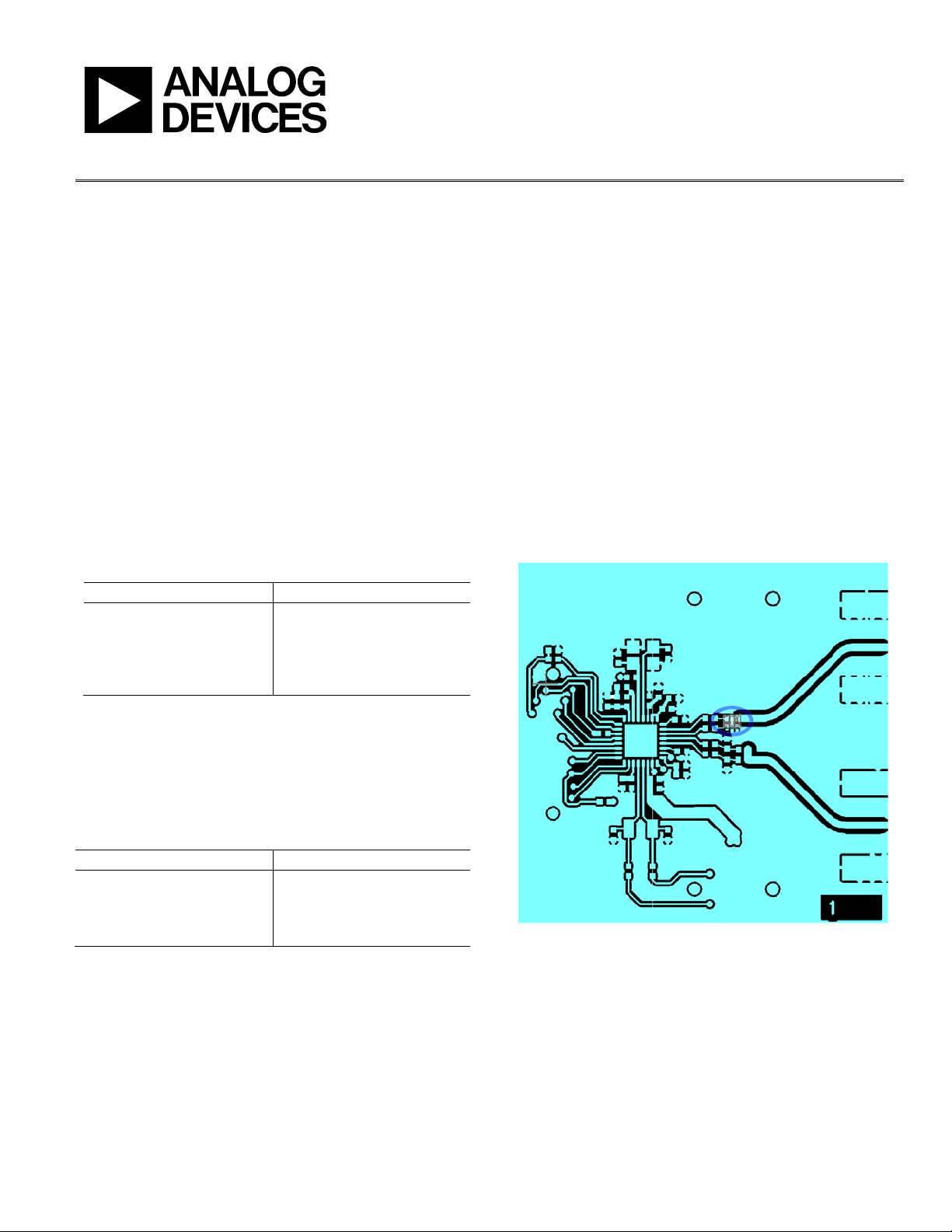
EVALUATION BOARD LAYO UT
An outline of the RF board layout is shown in Figure 1. Gerber
files of the board layout are available on the Analog Devices, Inc.,
ADF7242 evaluation board product website. Because the imped-
ance seen by the balun is inherently dependent on the layout,
it is recommended to follow the EVAL-ADF724xDB3Z layout
as shown in the Gerber files as closely as possible for optimum
performance.
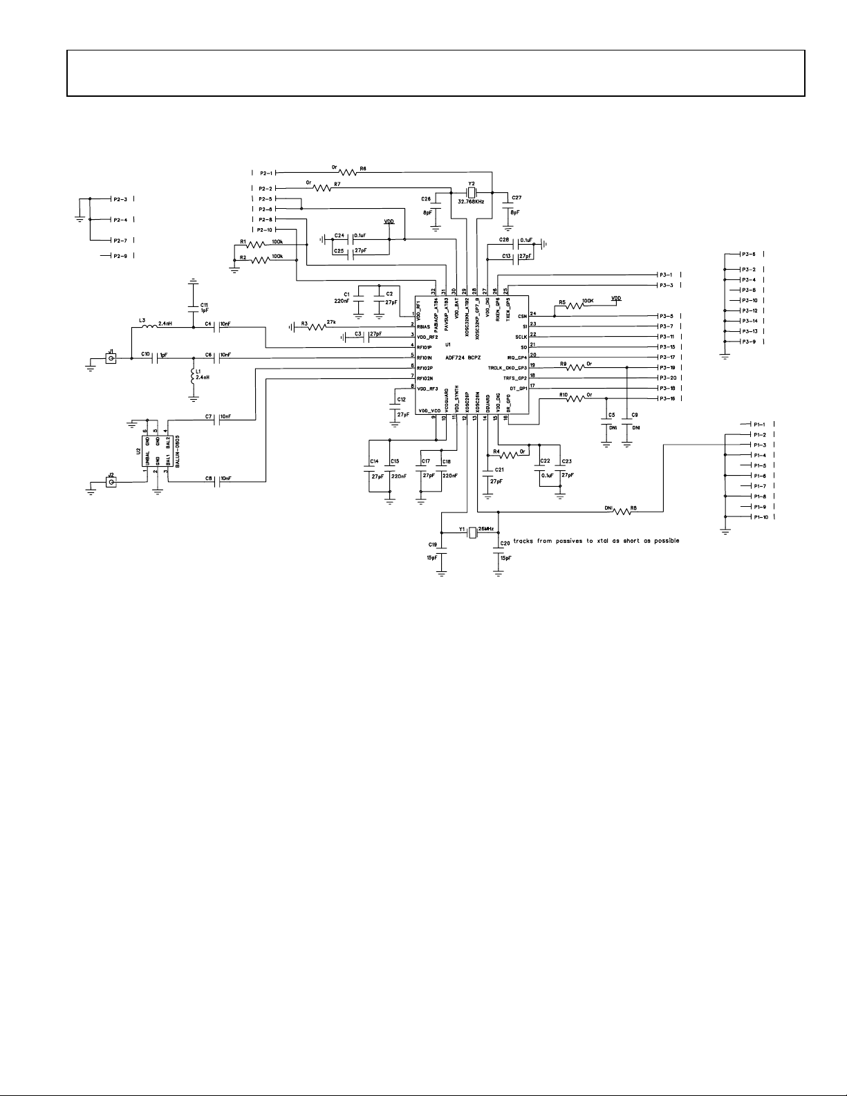
The board schematic is shown in Figure 2. Note that the C7 and
C8 capacitors are required for power amplifier stability, and the
specified 10 nF value should be used.
2. Typical Performance of the ADF7241 and ADF7242
Table
Using the 2450BM14E0007 Filter Balun
Parameter Value
Tx Output Power 3 dBm
Harmonics
4.9 GHz −50 dBm
7.35 GHz −47 dBm
Figure 1. EVAL-ADF724xDB3Z Board Layout Highlighting Balun Location
Rev. 0 | Page 1 of 8
Page 2

AN-1151 Application Note
TABLE OF CONTENTS
Introduction ...................................................................................... 1
Typical Performance Data ............................................................... 1
Evaluation Board Layout ................................................................. 1
REVISION HISTORY
5/12—Revision 0: Initial Version
Revision History ................................................................................2
Evaluation Board Schematic ............................................................3
Additional Information from Johanson Technology ....................4
Rev. 0 | Page 2 of 8
Page 3
Application Note AN-1151
10634-002
EVALUATION BOARD SCHEMATIC
Figure 2. EVAL-ADF724xDB3Z Schematic
Rev. 0 | Page 3 of 8
Page 4

AN-1151 Application Note
2.4 GHz Impedance-Matched Balun-Filter Integrated Passive for ADF7241 and AADF7242
P/N 2450BM14E0007
Detai l Specification:
Page 1 of 3
Gen eral Speci f icati on s
Part Number Insertion Loss
Frequency (MHz) Return Loss
Unbalanced Impedance (Antenna Out)
Phase Difference
Amplitude Difference
Reel Quanity
Operating Temperature
Power Capacity
Packaging
Bulk Suffix = S
Eg. 2450BM14E0007S
P/N
Style
T & R (Paper)
Suffix = E Eg. 2450BM14E0007T
Suffix
AgPt Suffix = None
Eg. 2450BM14E0007(S or T)
No. Function
1
Mechani cal Di mension s
2
In mm 3
L ± ± 4
W ± ± 5
T ± ± 6
a ± ±
b
c ± ±
g ± ±
p ± ±
Mounting Considerations
Mount these devices with brown mark facing up.
Units: mm
SAC 305 Solder Paste Recommended
Units: mm
Johanson Technology, Inc. reserves the right to make design changes w ithout notice.
All sales are subject to Johanson Technology, Inc. terms and conditions.
www.johansontechnology.com
4001 Calle Tecate • Camarillo, CA 93012 • TEL 805.389.1166 FAX 805.389.182
2012 Johanson Technology, Inc. All Rights Reserved
5/15/2012
Attenuation (dB)
25min.@4800~5000MHz
25min.@7200~7500MHz
0.012
0.004
0.30
0.10
0.004
0.063
1.60
0.10
0.10
0.80
0.031
0.004
Balanced Differential Impedance
*
Line w idth should be designed to provide 50 Ω
impedance matching characteristics.
0.020
0.002
0.10
0.50
0.05
0.024
0.006
0.15
+.004/-.006
+0.1/-0.15
0.004
0.10
0.008
0.008
0.004
0.20
0.10
0.20
GND
Unbalanced Port
0.60
GND
GND
Balanced Port
Balanced Port
0.004
1.5 dB max.
50 Ω
2400 - 2500
2450BM14E0007
Termination Style
2W max.
Conjugate m atch to ADI
ADF7241 and ADF7242
4,000
2.0 dB max.
180° ± 10°
9.5 dB min.
-40 to +85°C
Recommended Storage
Temperature
+5 to +35°C, Humidity:
45-75%RH, 18 mos. Max *
Terminal Configuration
L
W
c
a p
g
b
T
1
2
3
4
5
6
High Freq uency Ceramic S olution s
Land
Solder Resist
Through-hole
( f 0.2/ 0.35)
*18 months i n vacuum s eal ed bag and 1 week cumulat i ve after opened. For more i nfo g o to www.johansontechnology.c om/silverleads .ht ml
*
0.55
0.25
0.3
0.25
ADF724X
10nF caps (f or
DC-Block)
ADDITIONAL INFORMATION FROM JOHANSON TECHNOLOGY
The following content and logos are provided courtesy of Johanson Technology, Inc. Johanson Technology is an independent corporation
and is not owned by, controlled by, or an affiliate of Analog Devices, Inc. Analog Devices, Inc., makes no representations or warranties
with respect to the Johanson 2450BM14E007 or any other Johanson Technology products.
Rev. 0 | Page 4 of 8
Page 5

Application Note AN-1151
Preliminary
2.4 GHz Impedance-Matched Balun-Filter Integrated Passive for ADF7242 P/N 2450BM14E0007
Detail Specificati on: 02/15/12 Page 2 of 3
Layout Details
Johanson Technology, Inc. reserves the right to make design changes without noti ce.
All sales are subject t o Johanson Technology, Inc. terms and conditions.
www.johansontechnology.com
4001 Calle Tecate • Camarillo, CA 93012 • TEL 805.389.1166 FAX 805.389.1821
2012 Johanson Technology, Inc. All Rights Reserved
)
)
)
)
)
)
High Frequency Ceramic Solutions
Rev. 0 | Page 5 of 8
Page 6

AN-1151 Application Note
Preliminary
2.4 GHz Impedance-Matched Balun-Filter Integrated Passive for ADF7242 P/N 2450BM14E0007
Detail Specificati on: 02/15/12 Page 3 of 3
Typical Electrical Performance (T=25°C)
Actual Picture:
Johanson Technology, Inc. reserves the right to make design changes without noti ce.
All sales are subject t o Johanson Technology, Inc. terms and conditions.
www.johansontechnology.com
4001 Calle Tecate • Camarillo, CA 93012 • TEL 805.389.1166 FAX 805.389.1821
2012 Johanson Technology, Inc. All Rights Reserved
)))
)
)
)
High Frequency Ceramic Solutions
3 4 5 6 72 8
-40
-30
-20
-10
-50
0
freq, GHz
dB(IL)
dB(RL)
2.52.0 3.0
-10
0
10
-20
20
-100
0
100
-200
200
freq, GHz
dif_Amplitude
dif_Phase
Insertion Loss
Return Loss
Rev. 0 | Page 6 of 8
Page 7

Application Note AN-1151
NOTES
Rev. 0 | Page 7 of 8
Page 8

AN-1151 Application Note
©2012 Analog Devices, Inc. All rights reserved. Trademarks and
NOTES
registered trademarks are the property of their respective owners.
AN10634-0-5/12(0)
Rev. 0 | Page 8 of 8
 Loading...