

Page 1
UMTS Digital Gain Control
Amplifier, 1.94 - 2.34 GHz
V 1E.00
Advanced
AM55-0027
Features
n Digitally Controlled Gain Block
n Parallel Control Interface
n 4mm FQFP-N Package
n Single Positive Supply Voltage
n 0.25 dB Steps of Attenuation
n 10 dB Atttenuation Range
Description
M/A-COM’s AM55-0027 is a digitally controlled Variable
Gain Amplifier. Attenuation range is 10 dB with
Attenuation Steps of 0.25 dB. Attenuation is controlled
digitally through a parallel interface.
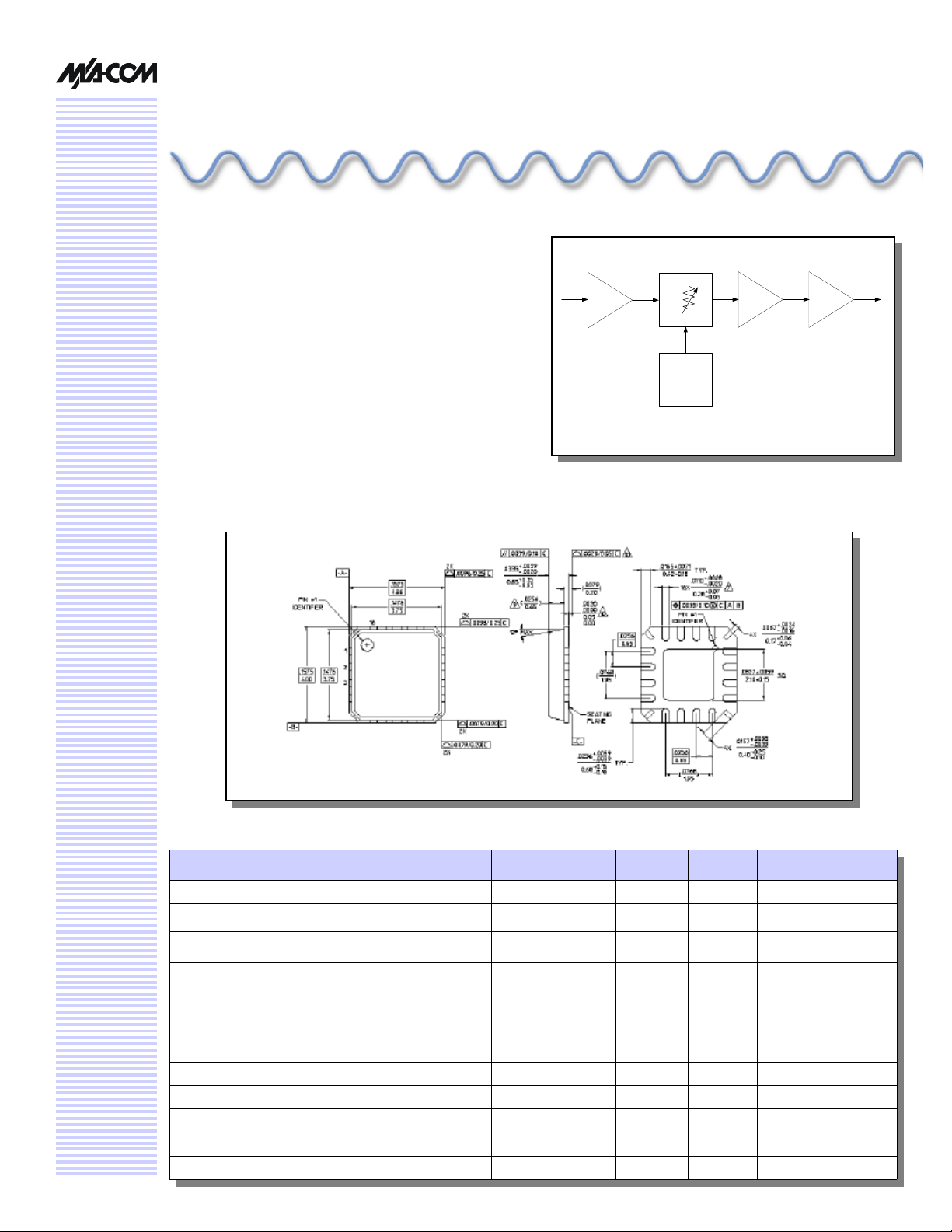
4mm FQFP-N Package Style
Block Diagram
10 dB
IN
8 dB
Gain
Range
in
0.25 dB
Steps
Parallel
Control
Interface
8 dB
Gain
9 dB
Gain
OUT
Electrical Specifications: TA = 25°C, Z0 = 50Ω, VS = 5V
Parameter Conditions Frequency Units Min. Typ. Max.
Gain No Attenuation 1.94 - 2.34 GHz dB 24 26 —
Attenuation Range — 1.94 - 2.34 GHz dB 10 10 —
Attenuation Step Size — 1.94 - 2.34 GHz dB 0.2 0.25 0.3
Amplitude Flatness —
All attenuation states
Input Return Loss — 1.94 - 2.34 GHz dB 13 18 —
Output Return Loss — 1.94 - 2.34 GHz dB 10 14 —
Output P1 dB 0 dB attenuation 1.94 - 2.34 GHz dBm 15 19 —
Output IP3 0 dB attenuation 1.94 - 2.34 GHz dBm 30 31 —
Noise Figure 0 dB attenuation 1.94 - 2.34 GHz dB — 4.7 —
Noise Figure 10 dB attenuation 1.94 - 2.34 GHz dB — 9.0 —
Supply Current — — mA — 110 120
1.94 - 2.34 GHz
2.09 - 2.19 GHz
dB
dB
—
—
—
—
± 0.3
± 0.1
Page 2
UMTS Digital Gain Control Amplifier, 1.94 - 2.34 GHz
AM55-0027
V 1E.00
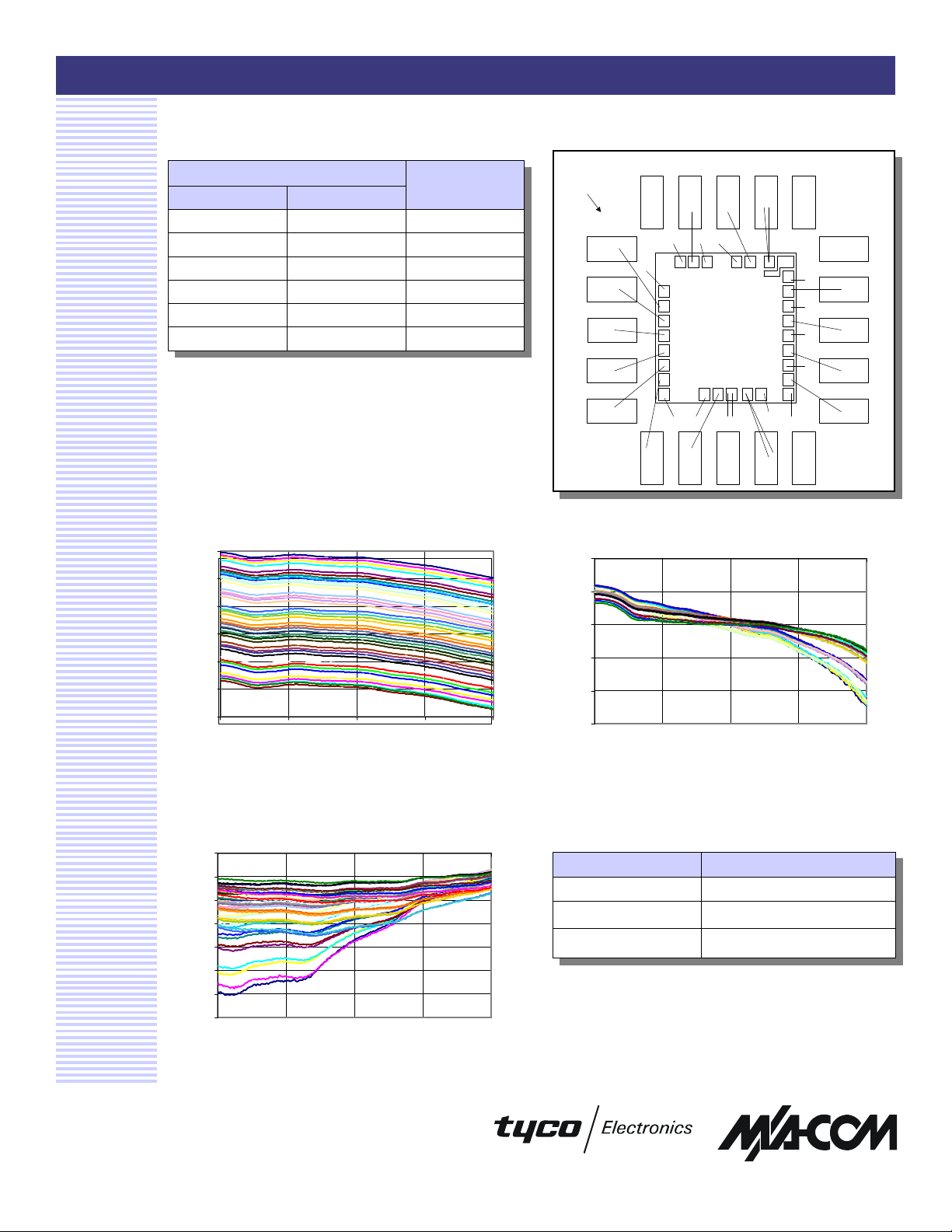
Pin Out Table
Control Pin
5V 0V
Vcc6 0.25 dB
Vcc1 0.5 dB
Vcc2 1 dB
Vcc3 Vcc3N 2 dB
Vcc4 Vcc4N 4 dB
Vcc5 Vcc5N 8 dB
*All Vdd pins = 5V
Example: To get 7.5 dB Attenuation Vcc4 = 5V, Vcc4N = 0V,
Vcc3 = 5V, Vcc3N = 0V, Vcc2 = 5V and Vcc1 = 5V
Note: In this case Vcc5 = 0V therefore Vcc5N is 5V, and
Vcc6 = 0
Attenuation
State
Typical Performance Curves
27
25
23
21
S21 (dB)
19
17
Pin Out Figure
Pin #20
Pin #1
VCC1
VCC3N
VDD
VCC5N
VCC4N VCC4
VCC6 N/CVDD1 RF IN N/C
Input Return Loss vs. Frequency Gain vs. Frequency
-10
-15
-20
-25
S11 (dB)
-30
N/CRF OUTVDD3VDD2 N/C
N/C
VCC3
VCC5
VCC2
15
1.94 2.04 2.14 2.24 2.34
Frequency (GHz)
Output Return Loss vs. Frequency
-10
-12
-14
-16
-18
S22 (dB)
-20
-22
-24
1.94 2.04 2.14 2.24 2.34
Frequency (GHz)
Specifications subject to change without notice.
n North America: Tel. (800) 366-2266
n Asia/Pacific: Tel.+81-44-844-8296, Fax +81-44-844-8298
n Europe: Tel. +44 (1344) 869 595, Fax+44 (1344) 300 020
Visit www.macom.com for additional data sheets and product information.
-35
1.94 2.04 2.14 2.24 2.34
Frequency (GHz)
Ordering Information
Part Number Package
AM55-0027 Bulk Packaging
AM55-0027TR Tape and Reel (1K Reel)
AM55-0027-TB Units Mounted on Test Board
2
 Loading...