

Page 1
WJ Communications, Inc. • Phone: 1-800-WJ1-4401 • FAX:408-577-6620 • e-mail:sales@wj.com • Web site: www.wj.com February 2002
AH2
Product Description
The AH2 is a general purpose, high dynamic
range amplifier targeting cable TV markets.
The combination of gain flatness, high linearity and bandwidth make it ideal for CATV distribution, cable modem and laser diode driver
applications. The AH2 is designed for 75 ohm
systems and requires minimal off chip biasing
elements. The device is manufactured using
GaAs MESFET technology and boasts an
MTBF of >100 years
3
at a mounting temperature of 85°C. All devices are 100% RF and DC
tested.
Product Features
•
50-860 MHz
•
-75 dBc CTB, 83 Channels
•
-53 dBc CSO, 83 Channels
•
3.5 dB Noise Figure
•
14.5 dB Gain
•
+
20 dBm P1dB
•
MTBF >100 Years
•
Single +5 V Supply
Functional Diagram
Absolute Maximum Ratings
Parameter Rating
Operating Case Temperture -40 to +85°C
Storage Temperature -55 to +125°C
Supply Voltage +6.0 V
Input RF Power (continuous) +10 dBm
Operation of this device above any of these parameters may cause permanent damage.
Ordering Information
Part No. Description
AH2 High Dynamic Range CATV Amplifier
(Available in tape and reel)
AH2-PCB Fully Assembled Single Ended CATV
Application Circuit
High Dynamic Range CATV Amplifier
The Communications Edge
™
Specifications
Parameter Units Minimum Typical Maximum Condition
Frequency Range MHz 50-860
Supply Voltage V 5
Operating Current Range mA 120 150 180 Vdd = 5.0 V
Packaged Device into 75 Ohms
S21 - Gain dB 14.5
50 MHz
S21 - Gain dB 13.0 14.0
860 MHz
Output IP3 dBm 36 40
Output P1dB dBm 21
Noise Figure dB 3.5
Single Ended CATV Evaluation
Circuit
Current mA 150
S21 - Gain dB 14.5 50 MHz
S21 - Gain dB 13.7 860 MHz
S11 - Input Return Loss dB -12.0 Average Across Band
S22 - Output Return Loss dB -15.0 Average Across Band
Output IP3 dBm 40
Output IP2 dBm 47
Output P1dB dBm 20 68.7 dBmV
Noise Figure dB 3.5
CSO dBc -53 83 channels, 30 dBmV/ch, single
CTB dBc -75 83 channels, 30 dBmV/ch, single
1.Test conditions unless otherwise noted.T = 25˚C, Vdd = 5.0 V.
2. OIP3 measured with 2 tones at an output power of 5 dBm/tone separated by 10 MHz.The suppression on the largest IM3 product is used to calculate OIP3 using a 2:1 slope rule.
3. MTBF calculated with channel temperature at 155˚C.
Actual Size
4
123
Function Pin No.
Input 1
Ground 2
Output/Bias 3
Ground 4
Page 2
WJ Communications, Inc. • Phone: 1-800-WJ1-4401 • FAX:408-577-6620 • e-mail: sales@wj.com • Web site: www.wj.com February 2002
AH2
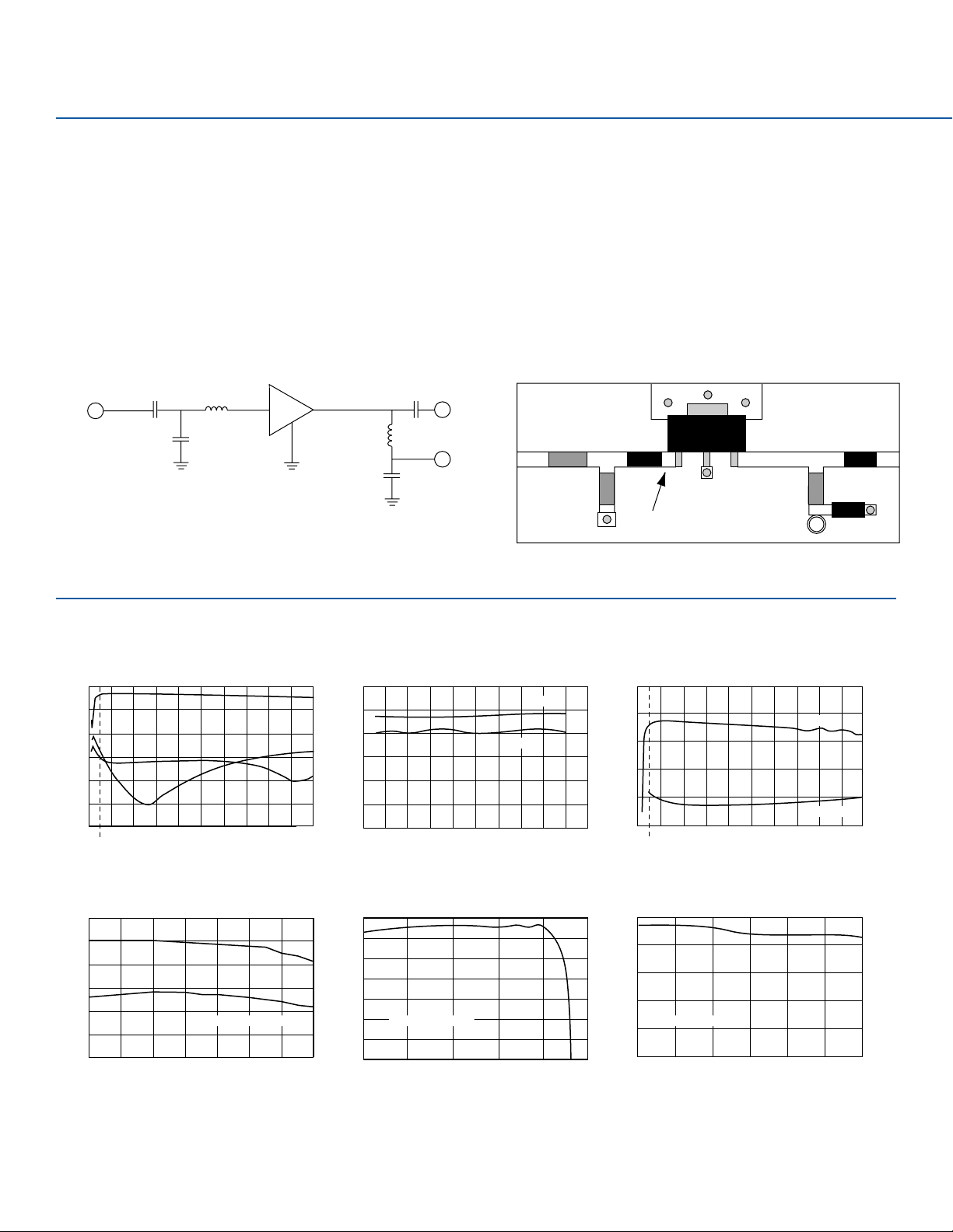
Single Ended CATV Evaluation Circuit: 50-860 MHz
Performance Charts
(Single Ended CATV Evaluation Circuit)
Typical Performance (75 Ohm System)
Frequency 50 MHz 450 MHz 750 MHz 860 MHz
Magnitude S21 14.5 dB 14.4 dB 14.0 dB 13.7 dB
Magnitude S11 -10.0 dB -11.2 dB -12.8 dB -16.9 dB
Magnitude S22 -8.8 dB -20.0 dB -11.6 dB -9.8 dB
OIP2 46.8 dBm 46.9 dBm 47.7 dBm 48.1 dBm
OIP3 39.8 dBm 40.7 dBm 41.0 dBm 40.8 dBm
Noise Figure 4.3 dB 3.4 dB 3.5 dB 3.6 dB
Bias Vds = 5 V, Id = 150 mA
Schematic
Optional
C = 1000pF
RF IN
C = 2.2 pF
L = 18 nH
AH2
3 or more Via
Grounds req.
L = 270 nH
C = 1000 pF
C = 1000 pF
Multi-channel Measurements
CSO -53 dBc 550 MHz 83 channels +30 dBmV/ch, Flat
CTB -75 dBc 550 MHz 83 channels +30 dBmV/ch, Flat
XMOD -70 dBc 550 MHz 83 channels +30 dBmV/ch, Flat
FR4 Board Layout (T = 28 Mils to ground plane)
RF OUT
0603 Package
C = 1000 pF
DC +5 V
0603 Package
C = 2.2 pF
Note: 0.5 dB of gain slope is due to the connector and board losses.
0603 Package
L = 18.0 nH
INPUT
Place inductor close to input
Length less than 100 mil
GND
GND
OUTPUT
1008 Package
L = 270 nH
Coilcraft
All Trans. Lines Z = 75 Ohm
0603 Package
C = 1000 pF
0603 Package
C = 1000 pF
+5 V
S-Parameters
20
10
0
-10
-20
Magnitude (dB)
-30
-40
0 10050200 300 400 500 600 700 800 900 1000
S21
S11
S22
Frequency (MHz)
OIP2 and OIP3 vs. Power
55
50
45
40
35
Intercept Point (dBm)
30
25
OIP2
OIP3
Frequency = 450 MHz
-4 -2 0 2 4 6 8 10
Output Power (dBm)
Noise Figure and Gain vs. Frequency Linearity vs. Frequency
60
50
40
30
20
Intercept Point (dBm)
10
00
0 100 200 300 400 500 600 700 800 900 1000
Frequency (MHz)
OIP2
OIP3
20
16
12
8
4
Noise Figure and Gain (dB)
0 10050200 300 400 500 600 700 800 900 1000
Frequency (MHz)
S21 (dB)
Noise Figure
Gain vs. Temperature Gain vs. Power Out
14
13
12
11
10
Gain (dB)
9
Frequency = 450 MHz
8
7
0 5 10 15 20 25
Output Power (dBm)
14.5
14.0
13.5
Gain (dB)
13.0
Frequency = 450 MHz
12.5
12.0
-40 -20 0 20 40 60 80
Temperature (°C)
Page 3

WJ Communications, Inc. • Phone: 1-800-WJ1-4401 • FAX:408-577-6620 • e-mail: sales@wj.com • Web site: www.wj.com February 2002
Push-Pull CATV Evaluation Circuit: 50-860 MHz
Performance Charts
(Push-Pull CATV Evaluation Circuit)
Thermal Specifications
Parameter Rating
Operating Case Temperature -40 to +85°C
Thermal Resistance (Maximum) 59°C/W
Junction Temperature +155°C
(Recommended Maximum)
Notes:
1.Thermal Resistance determined at Maximum Tab Temperature and Maximum Power
Dissipation.
2. Recommended Maximum Junction Temperature insures a MTBF of 1 million hours.
3. Refer to WJ Application Note “AH2 Temperature Effects on Reliability” for more information.
Typical Performance (75 Ohm System)
Frequency 50 MHz 450 MHz 750 MHz 860 MHz
Magnitude S21 11.1 dB 10.8 dB 10.6 dB 10.5 dB
Magnitude S11 -10.2 dB -9.7 dB -10.8 dB -11.0 dB
Magnitude S22 -13.3 dB -14.1 dB -15.4 dB -16.4 dB
OIP2 72.0 dBm 70 dBm 72 dBm 70 dBm
OIP3 42.0 dBm 43 dBm 41 dBm 40 dBm
Noise Figure 5.5 dB 4.3 dB 5.0 dB 5.4 dB
Bias Vds = 5 V, Id = 300 mA
Schematic
RF IN
6 Turns bifilar
wire around
ferrite core
R = 560
3 or more Via
Grounds req.
R = 560
C = 100 pF
AH2 6 Turns bifilar
C = 1000 pF
C = 100 pF
AH2
Core: TOK H5C2-T3.1-1.3-1.3
Wire: MWS B2383211
C = 1000 pF
L = 470 nH
DC +5 V
L = 470 nH
C = 1000 pF
wire around
ferrite core
or
MACOM
ETC1-1-13
surface mount
BALUN
Multi-channel Measurements
CSO -63 dBc 750 MHz 110 channels +40 dBmV/ch, Flat
CTB -61 dBc 750 MHz 110 channels +40 dBmV/ch, Flat
XMOD -81 dBc 750 MHz 110 channels +40 dBmV/ch, Flat
FR4 Board Layout (T = 28 Mils to ground plane)
Interior Trans. Lines Z = 37.5 Ohm
0603 Package
R = 560 ohm
RF OUT
0603 Package
R = 560 ohm
Note: 0.7 dB of loss is due to the balun and board losses.
0603 Package
C = 100 pF
0603
Package
C = 1000 pF
0603 Package
C = 100 pF
0603 Package C = 1000 pF
+5 V
0603 Package C = 1000 pF
1008 Package
L = 470 nH
Collcraft
S-Parameters
15
10
5
0
-5
Magnitude (dB)
-10
-15
-20
0 100 200 300 400 500 600 700 800 900 1000
S11
Frequency (MHz)
Linearity vs. Frequency
80
S21
S22
70
60
50
40
30
Intercept Point
20
V = 5V
10
I = 290 mA
0
0 100 200 300 400 500 600 700 800 900 1000
OIP2
Frequency (MHz)
OIP3
MTBF vs. Temperature
9
10
8
10
7
10
MTBF (hours)
Ground Tab
6
10
5
10
50 75 100 125 150 175 200
Temperature (°C)
Junction
Page 4

WJ Communications, Inc. • Phone: 1-800-WJ1-4401 • FAX:408-577-6620 • e-mail: sales@wj.com • Web site: www.wj.com February 2002
AH2
Outline Drawing
Specifications and information are subject to change without notice.
Caution! ESD sensitive device.
Land Pattern
Mounting Configuration
Page 5

WJ Communications, Inc. • Phone: 1-800-WJ1-4401 • FAX:408-577-6620 • e-mail: sales@wj.com • Web site: www.wj.com February 2002
AH2
T ypical Test Data
S-Parameters (Vds = +5 V, Ids = 150 mA,T = 22°C, unmatched device in a 75 ohm system)
Freq.(MHz) S11 (dB) S11 (Ang) S21 (dB) S21 (Ang) S12 (dB) S12 (Ang) S22 (dB) S22 (Ang)
50 -17.954 -34.607 15.494 173.263 -24.196 4.594 -24.261 -85.838
100 -17.783 -42.76 15.43 171.185 -24.137 2.039 -24.748 -86.372
150 -16.899 -48.969 15.372 168.082 -24.164 0.988 -23.994 -88.738
200 -15.938 -53.877 15.31 164.88 -24.169 0.271 -22.806 -91.71
250 -14.555 -58.607 15.222 162.051 -24.145 0.077 -22.955 -92.444
300 -12.921 -65.219 15.144 158.919 -24.172 -0.223 -22.997 -92.447
350 -12.349 -71.823 15.06 155.7 -24.073 -0.741 -22.025 -96.123
400 -11.647 -77.234 14.965 152.522 -24.104 -1.021 -21.072 -98.239
450 -10.998 -82.951 14.861 149.397 -23.993 -1.512 -20.276 -100.752
500 -10.427 -87.242 14.748 146.284 -24.03 -1.438 -19.506 -102.717
550 -9.883 -91.75 14.626 143.332 -24.004 -2.108 -18.842 -104.75
600 -9.444 -95.68 14.506 140.182 -23.955 -2.402 -18.262 -106.873
650 -9.002 -99.684 14.365 137.266 -23.911 -2.752 -17.732 -108.739
700 -8.556 -102.92 14.227 134.371 -23.939 -3.239 -17.206 -110.422
750 -8.231 -106.2 14.091 131.522 -23.898 -3.684 -16.756 -111.979
800 -7.887 -109.41 13.927 128.747 -23.896 -3.953 -16.398 -113.698
850 -7.534 -112.2 13.763 126.182 -23.837 -4.267 -16.016 -115.374
900 -7.252 -114.93 13.621 123.478 -23.832 -5.011 -15.656 -117.106
950 -6.974 -117.87 13.45 120.848 -23.827 -5.792 -15.328 -118.962
1000 -6.721 -120.3 13.29 118.273 -23.808 -5.852 -15.035 -121.085
Page 6

WJ Communications, Inc. • Phone: 1-800-WJ1-4401 • FAX:408-577-6620 • e-mail: sales@wj.com • Web site: www.wj.com February 2002
 Loading...