

Page 1
GQ
129
GQ-RELAYS
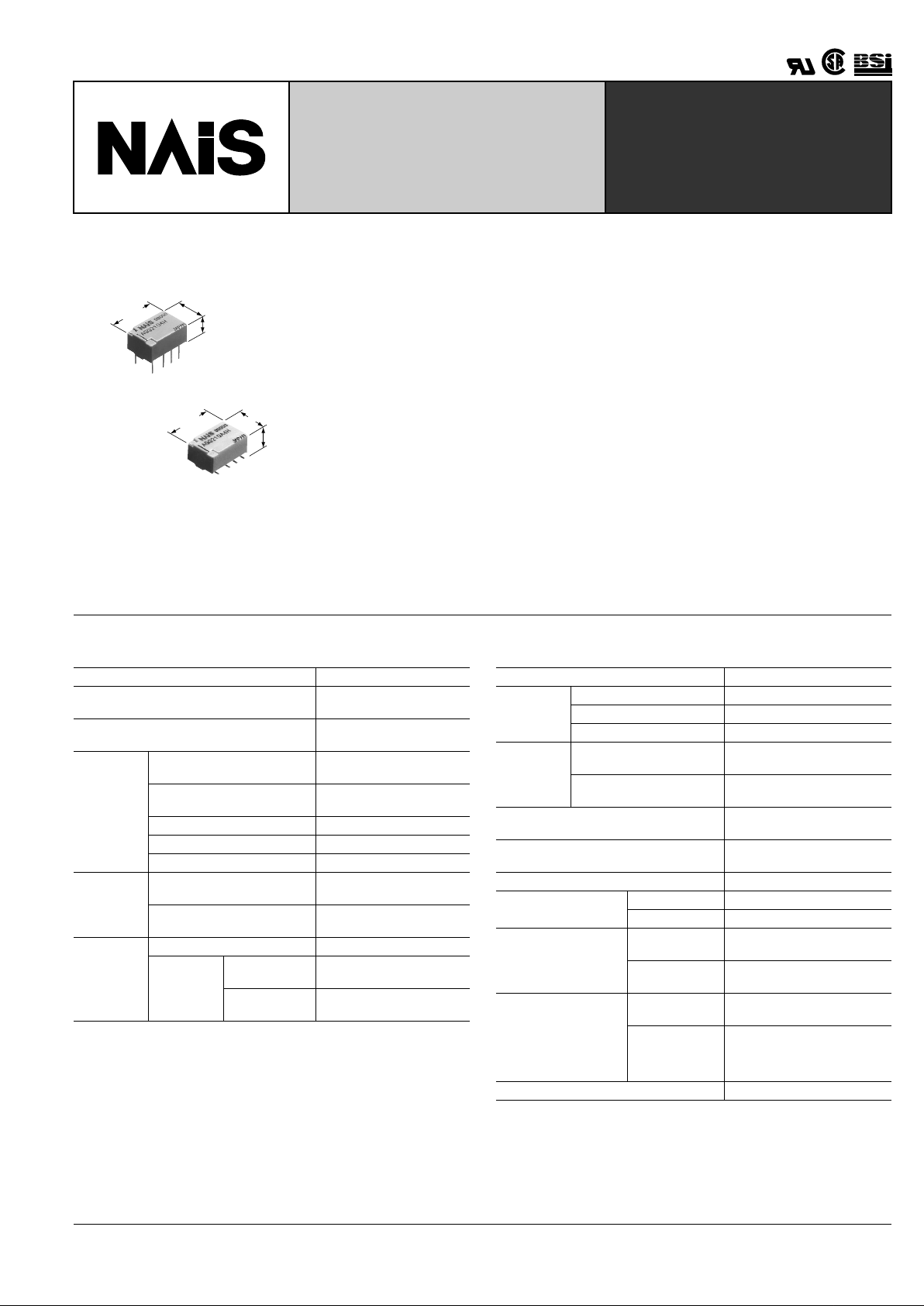
ULTRA-SMALL P ACKAGE
FLAT POLARIZED RELAY
7.20±0.3
.283±.012
10.60±0.3
.417±.012
5.20±0.2
.205±.008
10.60±0.3
.417±.012
Max.5.40
.213
7.20±0.3
.283±.012
mm inch
FEATURES
• Compact flat body saves space
With a small footprint of 10.6 mm (L) × 7.2
mm (W) .417 inch (L) × .283 inch (W) for
space savings, it also has a very short
height of 5.2 mm .205 inch. (Standard PC
board type.)
• Outstanding surge resistance.
Surge withstand between open contacts:
1,500 V 10 × 160 µ s (FCC part 68)
Surge withstand between contacts and
coil: 2,500 V 2 × 10 µ s (Bellcore)
• The use of twin cr ossbar contacts ensures high contact reliability.
AgPd contact is used because of its good
sulfide resistance. Adopting low-gas
molding material. Coil assembly molding
technology which avoids generating volatile gas from coil.
• Increased packaging density
Due to highly efficient magnetic circuit design, leakage flux is reduced and changes
in electrical characteristics from components being mounted close-together are
minimized. This all means a packaging
density higher than ever before.
• Nominal operating power: 140 mW
• Outstanding vibration and shock resistance.
Functional shock resistance:
750 m/s
2
{75G}
Destructive shock resistance:
1,000 m/s
2
{100G}
Functional vibration resistance:
10 to 55 Hz (at double amplitude of 3.3
mm .130 inch)
Destructive vibration resistance:
10 to 55 Hz (at double amplitude of 5 mm
.197 inch)
SPECIFICATIONS
Contact
Remarks:
* Specifications will vary with foreign standards certification ratings.
*
1
Measurement at same location as "Initial breakdown voltage" section.
*
2
Detection current: 10mA.
*
3
Nominal voltage applied to the coil, excluding contact bounce time.
*
4
By resistive method, nominal voltage applied to the coil; contact carrying current:
1 A.
*
5
Half-wave pulse of sine wave: 6 ms;detection time: 10 µ s.
*
6
Half-wave pulse of sine wave: 6 ms.
*
7
Detection time: 10 µ s .
*
8
Refer to 5. Conditions for operation, transport and storage mentioned in
AMBIENT ENVIRONMENT (Page 61)
Characteristics
Notes:
❇
1 This value can change due to the switching frequency , environmental conditions ,
and desired reliability level, therefore it is recommended to check this with the
actual load.
❇
2 The upper limit for the ambient temperature is the maximum temperature that
can satisfy the coil temperature rise. Under the packing condition, allowable
temperature range is from –40 to +70 ° C –40 ° to +158 ° F.
Arrangement 2 Form C
Initial contact resistance, max.
(By voltage drop 6 V DC 1A )
100 m Ω
Contact material
Stationary: AgPd+Au clad
Movable: AgPd
Rating
Nominal switching capacity
(resistive load)
1 A 30 V DC
0.3 A 125 V AC
Max. switching power
(resistive load)
30 W, 37.5 V A
Max. switching voltage 110 V DC, 125 V AC
Max. switching current 1 A
Min. switching capacity ❇ 1 10 µ A 10 mV DC
Nominal
operating
power
Single side stable
140mW (1.5 to 12 V DC)
230mW (24 V DC)
1 coil latching
100mW (1.5 to 12 V DC)
120mW (24 V DC)
Expected
life (min.
operations)
Mechanical (at 180 cpm) 5 × 10
7
Electrical
(at 20 cpm)
1 A 30 V DC
resistive
10
5
0.3 A 125 V AC
resistive
10
5
Initial insulation resistance*
1
Min. 1,000M Ω (at 500V DC)
Initial
breakdown
voltage*
2
Between open contacts 750 Vrms for 1min.
Between contact sets 1,000 Vrms for 1min.
Between contacts and coil 1,500 Vrms for 1min.
Initial surge
voltage
Between open contacts
(10 × 160 µ s)
1,500 V(FCC Part 68)
Between contacts and coil
(2 × 10 µ s)
2,500 V(Bellcore)
Operate time [Set time]*
3
(at 20 ° C)
Max. 4 ms (Approx. 2 ms)
[Max. 4 ms (Approx. 2 ms)]
Release time (without diode)
[Reset time]*
3
(at 20 ° C)
Max. 4 ms (Approx. 1 ms)
[Max. 4 ms (Approx. 2 ms)]
Temperature rise*
4
(at 20 ° C) Max. 50 ° C
Shock resistance
Functional*
5
Min. 750 m/s
2
{75G]
Destructive*
6
Min. 1,000 m/s
2
{100G]
Vibration resistance
Functional*
7
10 to 55 Hz at double
amplitude of 3.3 mm
Destructive
10 to 55 Hz at double
amplitude of 5 mm
Conditions for operation, transport and
storage*
8
(Not freezing and condensing at low temperature)
Ambient
temperature ❇ 2
–40 ° C to 85 ° C
–40 ° F to 185 ° F
Humidity 5 to 85% R.H.
Unit weight Approx. 1 g .035 oz
TESTING
Page 2
GQ
130
TYPICAL APPLICATIONS
• Telephone exchange, transmission
equipment
• Communications devices
• Measurement devices
• Home appliances, and audio/visual
equipment
• Handheld and portable products
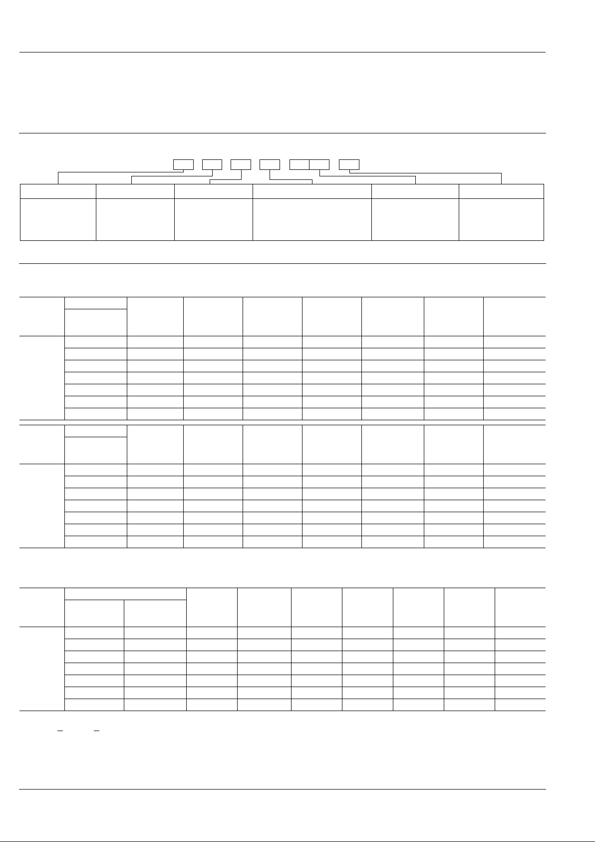
ORDERING INFORMATION
200A Z1HEx. AGQ
Contact arrangement
Terminal shapeOperating function Packing style
Coil voltage (DC)
Nil: Standard PC board terminal
A: Surface-mount terminal A type
S: Surface-mount terminal S type
2: 2 Form C 0: Single side stable
1: 1 coil latching
Type of operation
0: Standard type
(B.B.M.)
Nil: Tube packing
Z:
Tape and reel packing
(piked from 5/6/7/8
pin side)
1H: 1.5V
03 : 3V
4H: 4.5V
06 : 6V
09 : 9V
12 : 12V
24 : 24V
Note: Tape and reel packing symbol “-Z” is not marked on the relay. “X” type tape and reel packing (picked from 1/2/3/4-pin side) is also available. Suffix “X” instead of “Z”.
TYPES AND COIL DATA (at 20 ° C 68 ° F)
(1) Standard PC board terminal
1) Standard packing: 50 pcs. in an inner package (tube); 1,000 pcs. in an outer package
2) Specified value of pick-up, drop-out, set and reset voltage is with the condition of square wave coil pulse.
(2) Surface-mount terminal
❍
: For each surface-mounted terminal variation, input the following letter.
A type: A
, S type: S
1) Standard packing: 50 pcs.(tube), 900pcs. (tape and reel)in an inner package; 1,000 pcs.(tube), 1,800pcs. (tape and reel)in an outer package
2) Specified value of pick-up, drop-out, set and reset voltage is with the condition of square wave coil pulse.
Operating
Function
Part No.
Coil Rating,
V DC
Pick-up volt-
age, V DC
(max.)
(initial)
Drop-out
voltage,
V DC (min.)
(initial)
Nominal
operating
current,
mA ( ± 10%)
Coil resistance,
Ω ( ±
10%)
Nominal
operating
power, mW
Max. allowable
voltage,
V DC
Standard PC
board terminal
Single side
stable
AGQ2001H 1.5 1.13 0.15 93.8 16 140 2.25
AGQ20003 3 2.25 0.3 46.7 64.2 140 4.5
AGQ2004H 4.5 3.38 0.45 31 145 140 6.75
AGQ20006 6 4.5 0.6 23.3 257 140 9
AGQ20009 9 6.75 0.9 15.5 579 140 13.5
AGQ20012 12 9 1.2 11.7 1,028 140 18
AGQ20024 24 18 2.4 9.6 2,504 230 28.8
Operating
Function
Part No.
Coil Rating,
V DC
Set voltage,
V DC (max.)
(initial)
Reset voltage,
V DC (max.)
(initial)
Nominal
operating
current,
mA ( ± 10%)
Coil resistance,
Ω ( ±
10%)
Nominal
operating
power, mW
Max. allowable
voltage,
V DC
Standard PC
board terminal
1 coil
latching
AGQ2101H 1.5 1.13 1.13 66.7 22.5 100 2.25
AGQ21003 3 2.25 2.25 33.3 90 100 4.5
AGQ2104H 4.5 3.38 3.38 22.2 202.5 100 6.75
AGQ21006 6 4.5 4.5 16.7 360 100 9
AGQ21009 9 6.75 6.75 11.1 810 100 13.5
AGQ21012 12 9 9 8.3 1,440 100 18
AGQ21024 24 18 18 5.0 4,800 120 36
Operating
Function
Part No.
Coil Rating,
V DC
Pick-up
voltage,
V DC (max.)
(initial)
Drop-out
voltage,
V DC (min.)
(initial)
Nominal
operating
current,
mA ( ± 10%)
Coil
resistance,
Ω ( ±
10%)
Nominal
operating
power,
mW
Max.
allowable
voltage,
V DC
Tube packing
Tape and reel
packing
Single side
stable
AGQ200 ❍ 1H AGQ200 ❍ 1HZ 1.5 1.13 0.15 93.8 16 140 2.25
AGQ200 ❍ 03 AGQ200 ❍ 03Z 3 2.25 0.3 46.7 64.2 140 4.5
AGQ200 ❍ 4H AGQ200 ❍ 4HZ 4.5 3.38 0.45 31 145 140 6.75
AGQ200 ❍ 06 AGQ200 ❍ 06Z 6 4.5 0.6 23.3 257 140 9
AGQ200 ❍ 09 AGQ200 ❍ 09Z 9 6.75 0.9 15.5 579 140 13.5
AGQ200 ❍ 12 AGQ200 ❍ 12Z 12 9 1.2 11.7 1,028 140 18
AGQ200 ❍ 24 AGQ200 ❍ 24Z 24 18 2.4 9.6 2,504 230 28.8
Page 3

GQ
131
❍
: For each surface-mounted terminal variation, input the following letter.
A type: A, S type: S
1) Standard packing: 50 pcs.(tube), 900pcs. (tape and reel)in an inner package; 1,000 pcs.(tube), 1,800pcs. (tape and reel)in an outer package
2) Specified value of pick-up, drop-out, set and reset voltage is with the condition of square wave coil pulse.
Operating
Function
Part No.
Coil Rating,
V DC
Set voltage,
V DC (max.)
(initial)
Reset
voltage,
V DC (max.)
(initial)
Nominal
operating
current,
mA ( ± 10%)
Coil
resistance,
Ω ( ±
10%)
Nominal
operating
power,
mW
Max.
allowable
voltage,
V DC
Tube packing
Tape and reel
packing
1 coil
latching
AGQ210 ❍ 1H AGQ210 ❍ 1HZ 1.5 1.13 1.13 66.7 22.5 100 2.25
AGQ210 ❍ 03 AGQ210 ❍ 03Z 3 2.25 2.25 33.3 90 100 4.5
AGQ210 ❍ 4H AGQ210 ❍ 4HZ 4.5 3.38 3.38 22.2 202.5 100 6.75
AGQ210 ❍ 06 AGQ210 ❍ 06Z 6 4.5 4.5 16.7 360 100 9
AGQ210 ❍ 09 AGQ210 ❍ 09Z 9 6.75 6.75 11.1 810 100 13.5
AGQ210 ❍ 12 AGQ210 ❍ 12Z 12 9 9 8.3 1,440 100 18
AGQ210 ❍ 24 AGQ210 ❍ 24Z 24 18 18 5.0 4,800 120 36
DIMENSIONS
1. PC board terminal
10.60±0.3
.417±.012
0.40±0.1
.016±.004
2.20±0.15
.087±.006
2.20±0.15
.087±.006
3.20±0.15
.126±.006
3.50±0.3
.138±.012
5.20±0.2
.205±.008
7.20±0.3
.283±.012
0.20±0.1
.008±.004
5.08±0.15
.200±.006
PC board pattern
Tolerance: ± 0.1 ± .004
5.08
.200
2.20
.087
2.20
.087
3.20
.126
8-0.85 dia.
8-.033 dia.
Schematic (Bottom view)
Single side stable
(Deenergized condition)
1 coil latching
(Reset condition)
Direction indication
4321
5678
Direction indication
4321
5678
mm inch
2. Surface-mount terminal
1) A type
10.60±0.3
.417±.012
0.40±0.1
.016±.004
Max. 5.40
.213
8.40±0.3
.331±.012
3.20±0.15
.126±.006
2.20±0.15
.087±.006
2.20±0.15
.087±.006
7.20±0.3
.283±.012
0.20±0.1
.008±.004
5.08±0.15
.200±.006
Suggested mounting pad
Single side stable/
1 coil latching
3.20
.126
2.20
.087
2.20
.087
0.80
.031
2.66
.105
6.74
.265
1) S type
10.60±0.3
.417±.012
Max. 5.40
.213
0.40±0.1
.016±.004
3.20±0.15
.126±.006
2.20±0.15
.087±.006
2.20±0.15
.087±.006
7.20±0.3
.283±.012
7.20±0.3
.283±.012
0.20±0.1
.008±.004
5.08±0.15
.200±.006
Suggested mounting pad
Single side stable/
1 coil latching
Tolerance: ±0.1 ±.004
3.20
.126
2.20
.087
2.20
.087
0.80
.031
2.06
.081
6.14
.242
Schematic (Top view)
Single side stable
(Deenergized condition)
1 coil latcing
(Reset condition)
Direction indication
4321
5678
Direction indication
4321
5678
REFERENCE DATA
1. Max. switching capacity 2. Life curve
30
100
Contact voltage, V
1.0
0.3
DC resistive load
AC resistive load
Switching current, A
Switching current, A
No. of operations, × 10
4
0.2 0.4 0.6 0.8 1.0 1.2
100
50
30
40
20
10
0
DC 30V resistive load
AC 125V
resistive load
Page 4

GQ
132
NOTES
1. Coil operating power
1) As a general rule, only a pure DC power supply should be used for the coil drive.
2) To ensure proper operation, the voltage
applied to both terminals of the coil should
be ±5% (at 20°C 68°F) the rated operating
voltage of the coil. Also , be aware that the
pick-up and drop-out voltages will fluctuate depending on the ambient temperature and operating conditions.
3) The ripple factor f or the voltage applied
to the coil should be less than 5%.
4) For set and reset latching relays, the
rated operating voltage should be applied
to the coil for 10 ms or more.
2. Coil connection
When connecting coils, refer to the wiring
diagram to prevent mis-operation or malfunction.
3. External magnetic field
Since GQ relays are highly sensitive polarized relays, their characteristics will be
affected by a strong external magnetic
field. A v oid using the rela y under that condition.
4. Cleaning
In automatic cleaning, cleaning with the
boiling method is recommended. A v oid ultrasonic cleaning which subject the relay
to high frequency vibrations. It may cause
the contacts to stick.
lt is recommended that a fluorinated hydrocarbon or other alcoholic solvent be
used.
5. Packing style
1) The relay is packed in a tube with the
relay orientation mark on the left side, as
shown in the figure below.
2) Tape and reel packing
(A type)
(1)-1 T ape dimensions
mm inch
(S type)
(1)-2 T ape dimensions
(2) Dimensions of plastic peel
mm inch
6. Automatic insertion
To maintain the internal function of the relay, the chucking pressure should not exceed the values below.
Chucking pressure in the direction A :
9.8 N {1 kgf} or less
Chucking pressure in the direction B :
9.8 N {1 kgf} or less
Chucking pressure in the direction C :
9.8 N {1 kgf} or less
Please chuck the portion.
Avoid chucking the center of the relay.
In addition, excessive chucking pressure
to the pinpoint of the relay should be also
avoided.
Orientation (indicates PIN No.1)stripe
Stopper (green) Stopper (red)
Orientation (indicates PIN No.1)stripe
Stopper (green) Stopper (red)
Relay polarity bar
(Z type)
Tape coming out direction
General tolerance ±0.1 mm .004 inch
1.50 dia.
.059 dia.
4.00
.157
0.40
.016
1.75
.069
2.00dia.
.079dia.
2.0
.079
12.0
.472
9.0
.354
Max. 6.55
.256
24.0±0.3
.945±.012
11.1
.437
11.5
.453
+0.1
0
+.003
.0
GQ relays
Relay polarity bar
(Z type)
Tape coming out direction
General tolerance ±0.1 mm .004 inch
4.0
.157
0.40
.016
1.75
.069
2.00dia.
.079dia.
2.0
.079
12.0
.472
7.8
.307
Max. 6.55
.256
11.5
.453
1.50 dia.
.059 dia.
+0.1
0
+.003
.0
GQ relays
11.1
.437
24.0±0.3
.945±.012
21±0.8 dia.
.827±.031 dia.
13±0.2 dia.
.512±.008 dia.
24.4
.961
+2
0
+.079
0
2.0±0.2
.079±.008
2.0±0.5
.079±.020
100±1 dia.
3.937±.039 dia.
330±2 dia.
12.992±.079 dia.
A
C
B
For Cautions for Use, see Relay Technical Information (Page 48 to 76).
9/1/2000 All Rights Reserved, © Copyright Matsushita Electric Works, Ltd.
Go To Online Catalog
 Loading...