

Datasheet AGM1232G-RLYW-T, AGM1232G-RLYS-T, AGM1232G-RLYH-T, AGM1232G-RLYD-T, AGM1232G-RLGS-T Datasheet (AZDIS)
...Page 1

AZ DISPLAYS, INC.
COMPLETE LCD SOLUTIONS
SPECIFICATIONS FOR
LIQUID CRYSTAL DISPLAY
PART NUMBER: AGM 1232G SERIES
DATE: APRIL 26, 2001
Page 2
AGM1232G SERIES GRAPHIC MODULE
AZ DISPLAYS, INC. 04/26/01
1
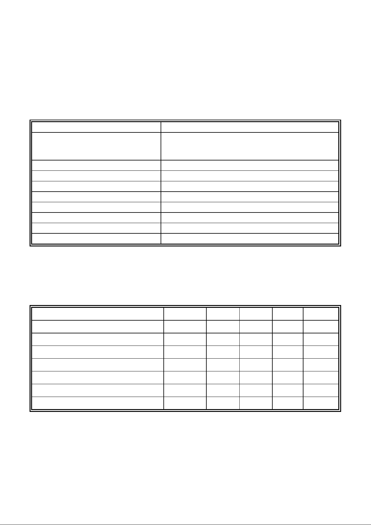
1.0 MECHANICAL SPECS
1. Item Description
2. Overall Module Size 84.0mm(W) x 44.0mm(H) x max 13.0mm(D) for LED backlight
version
84.0mm(W) x 44.0mm(H) x max 9.0mm(D) for reflective version
3. Dot Size 0.40mm(W) x 0.45mm(H)
4. Dot Pitch 0.44mm(W) x 0.49mm(H)
5. Duty 1/32
6. Controller IC SED1520FOA/DOA
7. LC Fluid Options STN, FSTN
8. Polarizer Options Reflective, Transflective, Transmissive
9. Backlight Options
LED
10. Temperature Range Options Standard (0ºC ~ 50ºC), Wide (-20ºC ~ 70ºC)
2.0 ABSOLUTE MAXIMUM RATINGS
Item Symbol Min Typ Max Unit
Operating temperature (Standard) Top 0 - 50 ºC
Storage temperature (Standard) Tst -20 - 70 ºC
Operating temperature (Wide temperature) Top -20 - 70 ºC
Storage temperature (Wide temperature) Tst -30 - 80 ºC
Input voltage Vin Vss Vdd V
Supply voltage for logic Vdd- Vss -0.3 - 7.0 V
Supply voltage for LCD drive Vdd- Vo 5.0 6.5 9.5 V
Page 3
AGM1232G SERIES GRAPHIC MODULE
AZ DISPLAYS, INC. 04/26/01
2
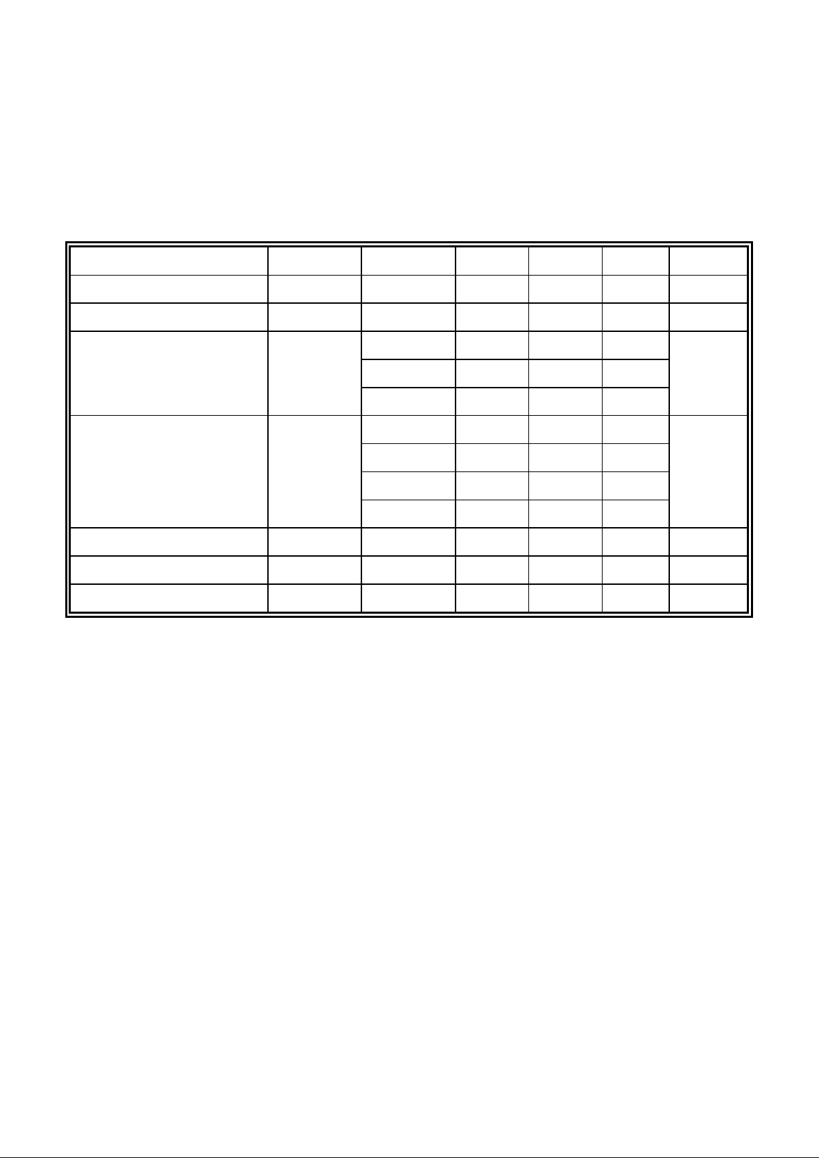
3.0 ELECTRICAL CHARACTERISTICS
Item Symbol Condition Min Typ Max Unit
Input voltage (high) Vih H level 3.5 - Vdd V
Input voltage (low) Vil L level 0 - 1.5 V
0ºC - 7.8 10.0
25ºC - 6.5 -
Recommended LC Driving
Voltage (Standard Temp)
Vdd - Vo
50ºC 4.3 5.5 -
V
-20ºC - 8.5 10.8
0ºC - 7.8 -
50ºC 4.3 5.5 -
Recommended LC Driving
Voltage (Wide Temp)
Vdd -Vo
70ºC 3.5 4.8 -
V
Power Supply Current Idd Vdd=5.0V - - 13.0 mA
LED Power Supply Voltage Vfled R=6.8Ω - 4.4 5.0 V
LED Power Supply Current Ifled R=6.8Ω - 300 420 mA
Page 4
AGM1232G SERIES GRAPHIC MODULE
AZ DISPLAYS, INC. 04/26/01
3
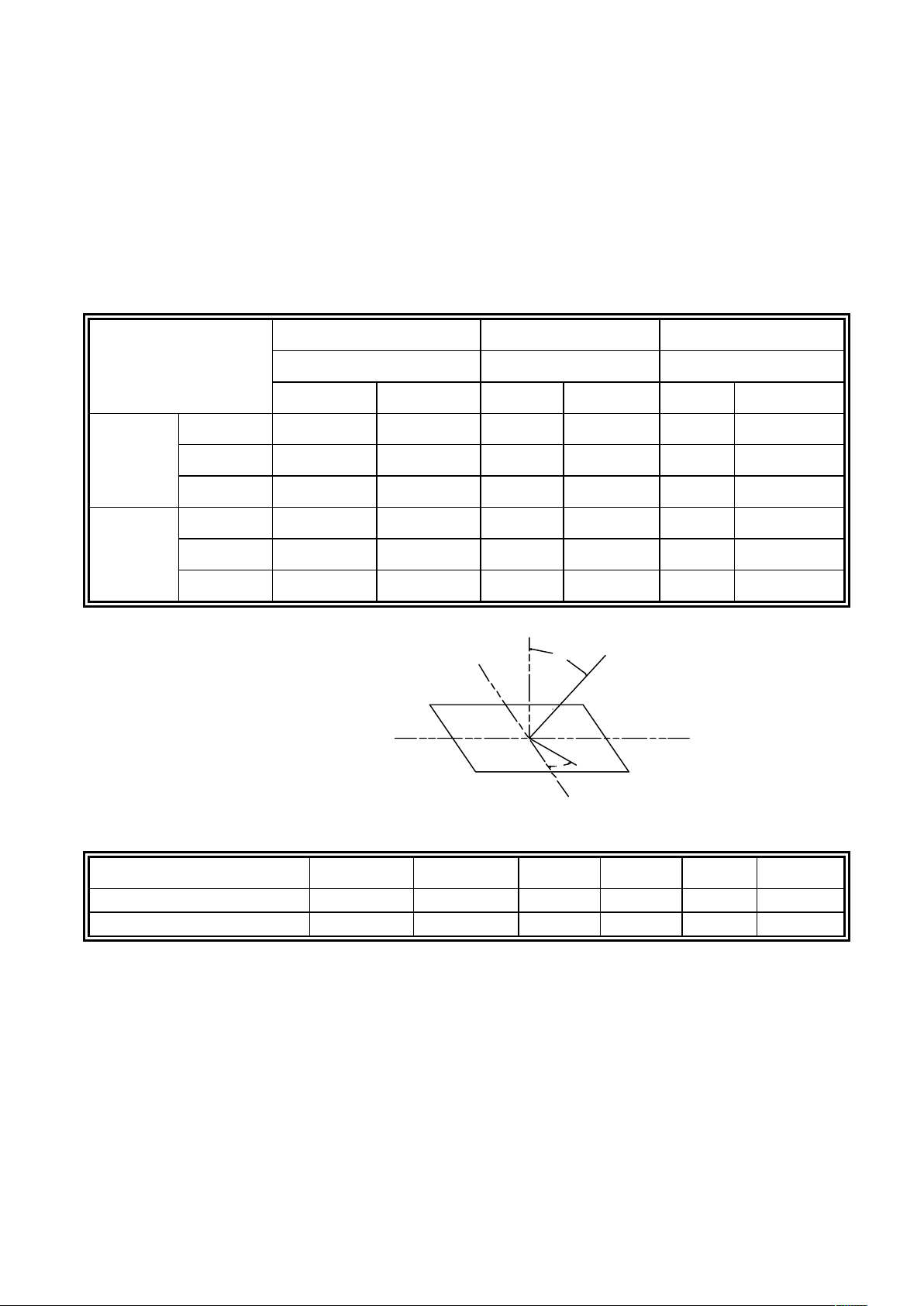
4.0 OPTICAL CHARACTERISTICS
Cr (Contrast Ratio) θ (Viewing Angle) φ (Viewing Angle)
25 C 25 C 25 C
Item
Mode
MIN. TYP. MIN TYP. MIN TYP.
A 2.8 3.05 80° 85° -35°
B 7.10 7.70 80° 85° -35°
R
C------
A 2.49 2.99 80° 85° -35°
B 7.05 7.55 80° 85° -35°
S
C------
Note:
R: Reflective
S: Transflective
A: STN Gray
B: STN Yellow
C: FSTN
At: φ =0°, θθ =0°
Item Symbol Condition Min Typ Max Unit
Response time (rise) Tr 25 C - 80 160 ms
Response time (fall) Tf 25 C - 50 100 ms
θ
φ
°
°°
°
°
Page 5

AGM1232G SERIES GRAPHIC MODULE
AZ DISPLAYS, INC. 04/26/01
4
5.0 BLOCK DIAGRAM
LCD 122x32
U2
U1
SEG1- 61
SEG 1
COM 17-32
8
LED BACKLIGHT
1. Vss
2. Vdd
3. Vo
4. A0
9. R/W
5. E1
10. DB0
17. DB7
~
+/A BL+
-/K BL-
61
COM 1-16
COM 1
COM 16
SEG62- 122
SEG62- 122
COM 17
COM 32
SEG 122 SEG 61 SEG 62
6. E2
Ck FR
61
20
19
Page 6

AGM1232G SERIES GRAPHIC MODULE
AZ DISPLAYS, INC. 04/26/01
5
6.0 PIN ASSIGNMENT
Pin No. Symbol Function Level
1 Vss Ground -
2 Vdd Power Supply For Logic Circuit -
3Vo
Power Supply For LCD Driving
-
4 A0 Instruction/Data H/L
5E1 Enable for IC1 H/L
6E2 Enable for IC2 H/L
7NC
8NC
9 R/W
H: Data read
L: Data write
H/L
10 DB0 Data bit 0 H/L
11 DB1 Data bit 1 H/L
12 DB2 Data bit 2 H/L
13 DB3 Data bit 3 H/L
14 DB4 Data bit 4 H/L
15 DB5 Data bit 5 H/L
16 DB6 Data bit 6 H/L
17 DB7 Data bit 7 H/L
18
RES
Display Reset on active "Low"
19 BL- Power Supply for BL+ -
20
BL+ Power Supply for BL- -
H/L
Page 7

AGM1232G SERIES GRAPHIC MODULE
AZ DISPLAYS, INC. 04/26/01
6
7.0 POWER SUPPLY
8.0 TIMING CHARACTERISTICS
Item
Symbol
Test Condition
Min.
Typ.
Max.
Unit
System cycle time t
CYC6
Fig. a, Fig. b 1000 - - ns
Address setup time t
AW6
Fig. a, Fig. b 20 - - ns
Address hold time t
AH6
Fig. a, Fig. b 10 - - ns
Data hold time t
DH6
Fig. a 10 - - ns
Data setup time t
DS6
Fig. a 80 - - ns
Output disable time t
OH6
10 - 60 ns
Access time t
ACC6
CL=100 pF
- - 90
Read 100
Enable pulse
width
Write
T
EW
80
Rise and fall time Tr, T
f
Fig. a, Fig. b - - 15 ns
Page 8

AGM1232G SERIES GRAPHIC MODULE
AZ DISPLAYS, INC. 04/26/01
7
VIH1
VIL1
VIH1
IL1V
VIH1
IL1V
Valid Data
t H
R/W
E
DB0~DB7
VIH1
VIL1
A0,CS
IL1
IH1V
V
VIH1
t
VIL1
CYC6
EW
t
t
r
t
f
t
AW6t
ACC6
t
OH6
t
AH6
t
Fig. a Interface timing (data Read)
Valid Data
CYC6
EW
DS6
DB0~DB7
IL1V
A0,CS
R/W
E
AW6
IL1
IH1
V
V
IH1
IL1
V
V
t
IH1
V
r
t
t
t
t
IL1V
AH6
DH6
t
V
IH1
VIL1
VIH1
t
f
t
VIH1
VIL1
Fig. b Interface timing (data Write)
Page 9

AGM1232G SERIES GRAPHIC MODULE
AZ DISPLAYS, INC. 04/26/01
8
9.0 RELIABILITY TEST
Evaluations and Assessment*
Storage Condition Content
Current
Consumption
Oozing Contrast Other Appearances
Operation at high
temperature and
humidity
40º C,90%
RH,240hrs
Twice initial
value or less
none
More than 80% of
initial value
No abnormality
High temperature
storage
60º C,
240hrs
Twice initial
value or less
none
More than 80% of
initial value
No abnormality
Low temperature
storage
-20º C ,
240hrs
Twice initial
value or less
More than 80% of
initial value
No abnormality
*Evaluations and assessment to be made two hours after returning to room temperature (25º C±5 ºC).
*The LCDs subjected to the test must not have dew condensation.
Page 10

AGM1232G SERIES GRAPHIC MODULE
AZ DISPLAYS, INC. 04/26/01
9
10.0 MECHANICAL DIAGRAM
Page 11

AGM1232G SERIES GRAPHIC MODULE
AZ DISPLAYS, INC. 04/26/01
10
11.0 RELATION BETWEEN DISPLAY PATTERN AND DRIVERS
Page 12

AGM1232G SERIES GRAPHIC MODULE
AZ DISPLAYS, INC. 04/26/01
11
12.0 DISPLAY CONTROL INSTRUCTION
The display control instructions control the internal state of the SED1520DOA/FOA. Instructions are
received from MPU to SED1520DOA/FOA for the display control.
INSTRUCTION A0 R/W DB7 DB6 DB5 DB4 DB3 DB2 DB1 DB0 DESCRIPTION
Display ON/OFF 0 0 1 0 1 0 1 1 1 1/0
Turns display on or off.
0: OFF. 1:ON
Set Page Address 0 0 1 0 1 1 1 0 Page (0~3)
Sets display RAM Page in
Page address register
Set Column
(Segment address)
0 0 0 Column address (0~79)
Sets display RAM column
address in column address
register
Display Start
Line
0 0 1 1 0 Display start line (0~31)
Indicates the display data
RAM displayed at the top of
the screen.
Status Read 0 1
BUSY
ADC
ON/OFF
RESET
00 0 0
Reads the following status:
BUSY 0: Ready
1: Busy
ADC 1: CW output
0: CCW output
ON/OFF 0: Display on
1: Display off
RESET 0: Normal
1: Being Reset
Write Display Data 1 0 Write Data
Writes data DB0~DB7 from
bus into display data RAM.
Read Display Data 1 1 Read Data
Reads data DB0~DB7 from
display data RAM onto the
data bus.
Select ADC 0 010100000/10: CW output,1: CCW output
Static drive ON/OFF 0 010100100/1
1: Static drive,
0: Normal driving
Select duty 0 010101000/1
Select LCD duty cycle
1:1/32, 0: 1/16
Read-Modify-Write 0 011100000Read-Modify-write ON
END 0 011101110Read-Modify-write OFF
Reset 0 011100010Software reset
 Loading...