

Page 1
Alpha Industries, Inc. [781] 935-5150 • Fax [617] 824-4579 • Email sales@alphaind.com • www.alphaind.com 1
Specifications subject to change without notice. 6/99A
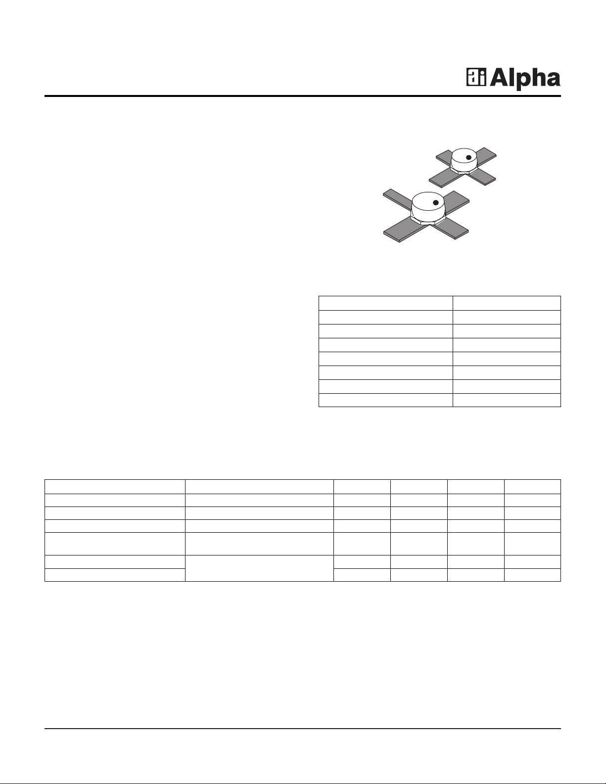
General Purpose Packaged PHEMT Chips
Features
■ Low Noise Figure, 1.55 dB @ 4 GHz
■ High Associated Gain, 13 dB @ 4 GHz
■ High MAG, > 15 dB @ 4 GHz
■ 0.7 µm Ti/Pd/Au Gates
■ Passivated Surface
■ Low Cost Metal Ceramic Package
■ Available with Two Lead Lengths
■ Available in Tape and Reel Packaging
Description
The AFP02N8-212, 213 are general purpose packaged
PHEMT chips that have excellent gain and noise
performance through X band, making them suitable for a
wide range of commercial applications. The devices
employ 0.7 µm Ti/Pd/Au gates and surf ace passiv ation to
ensure a rugged, reliable part. Available in metal cer amic
packages with a choice of two lead lengths. The
components are also available in tape and reel and are
ready for automatic insertion equipment.
AFP02N8-212, AFP02N8-213
Parameter Test Conditions Min. Typ. Max. Unit
Saturated Drain Current (I
DSS
)V
DS
= 2 V, VGS= 0 V 25.0 55.0 90.0 mA
Transconductance (gm) VDS= 2 V, IDS= 15 mA 30.0 45.0 mS
Pinch-off Voltage (VP) VDS= 2 V, IDS= 0.3 mA -0.4 -1.2 -2.0 V
Gate to Source IGS= -200 µA -6.0 8.0 V
Breakdown V oltage (V
bgs
)
Noise Figure (NF)
VDS= 2 V, IDS= 15 mA, F = 4 GHz
1.55 2.0 dB
Associated Gain (GA) 12.0 13.2 dB
Electrical Specifications at 25°C
Source
Gate
Source
Drain
Drain
Source Gate
Source
212
213
Characteristic Value
Drain to Source Voltage (VDS) 6 V
Gate to Source Voltage (VGS) -3 V
Drain Current (IDS) I
DSS
Gate Current (IGS) 10 µA
Total Power Dissipation (PT) 300 mW
Storage Temperature (TST) -65 to +150°C
Channel Temperature (TCH) 175°C
Absolute Maximum Ratings
Page 2
2 Alpha Industries, Inc. [781] 935-5150 • Fax [617] 824-4579 • Email sales@alphaind.com • www.alphaind.com
Specifications subject to change without notice. 6/99A
General Purpose Packaged PHEMT Chips AFP02N8-212, AFP02N8-213
0
4
8
12
16
20
24
0
024681012141618
1
2
3
4
6
5
NF
MIN
(dB)
G
A
(dB)
Frequency (GHz)
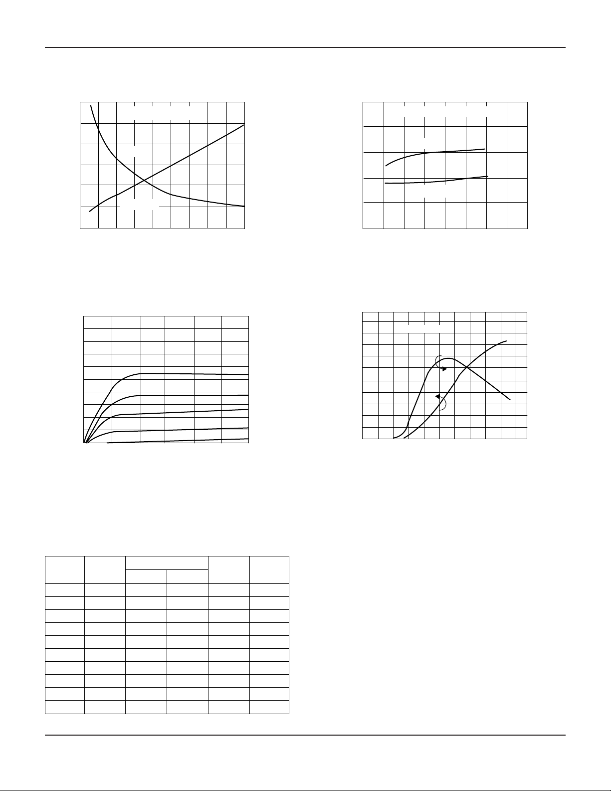
RF Minimum Noise Figure (NF
MIN
) and
Associated Gain (G
A
) vs. Frequency (GHz)
VDS = 2 V, IDS = 15 mA
GA (dB)
NF
MIN
(dB)
100
0 1.0 1.5 2.50.5 2.0 3.0
50
0
VDS (V)
l
DS
(mA)
DC Drain Current (IDS) vs. Drain Voltage (VDS)
as a Function of Gate to Source Voltage (V
GS
)
0 5 10 15 20 25 30 4035
IDS (mA)
NF
MIN
(dB)
G
A
(dB)
RF Minimum Noise Figure (NF
MIN
) and
Associated Gain (G
A
) vs. Drain Current (IDS)
F = 12 GHz, VDS = 2 V
0
2
4
6
8
10
0
2
4
6
10
8
NF
MIN
(dB)
GA (dB)
100
0
-2.0 -1.0 0
100
0
50
50
1.0
gm (mS)
VGS (V)
l
DS
(mA)
VDS = 2 V
DC Drain Current (IDS) and
Transconductance (gm) vs.
Gate to Source Voltage (V
GS
)
Typical Performance Data
Freq. NF
MIN
ΓΓ
opt
(GHz) (dB) Mag. Ang. RN/50 GA(dB)
1 0.75 0.84 25.40 0.12 23.50
2 1.10 0.72 50.20 0.23 18.00
4 1.55 0.54 99.00 0.23 13.20
6 2.00 0.43 145.40 0.15 10.20
8 2.50 0.39 -171.80 0.16 8.10
10 3.00 0.39 -133.60 0.32 6.51
12 3.50 0.43 -100.10 0.66 5.82
14 4.00 0.48 -71.10 1.16 5.20
16 4.50 0.55 -45.90 1.77 4.51
18 5.00 0.60 -23.30 2.38 4.10
Typical Noise Parameters
(V
DS
= 2 V, IDS= 15 mA)
Page 3

General Purpose Packaged PHEMT Chips AFP02N8-212, AFP02N8-213
Alpha Industries, Inc. [781] 935-5150 • Fax [617] 824-4579 • Email sales@alphaind.com • www.alphaind.com 3
Specifications subject to change without notice. 6/99A
Typical S-Parameters (VDS= 2 V, IDS= 10 mA)
Freq.
S
11
S
21
S
12
S
22
S
21
MAG/
(GHz) Mag. Ang. Mag. Ang. Mag. Ang. Mag. Ang. k (dB) MSG (dB)
2 0.907 -62.79 3.464 127.20 0.064 50.72 0.668 -34.68 0.28 10.79 17.33
3 0.838 -90.38 3.023 105.25 0.081 34.37 0.624 -48.83 0.41 9.61 15.72
4 0.783 -111.85 2.621 86.99 0.089 21.93 0.597 -60.61 0.56 8.37 14.69
5 0.736 -130.94 2.336 71.00 0.940 11.76 0.578 -69.70 0.71 7.37 13.95
6 0.678 -148.78 2.121 57.32 0.097 4.01 0.541 -75.33 0.93 6.53 13.40
7 0.646 -169.88 1.963 41.01 0.100 -6.30 0.529 -85.97 1.05 5.86 11.60
8 0.623 170.99 1.757 25.78 0.094 -16.83 0.498 -96.93 1.35 4.90 9.21
9 0.608 156.18 1.586 13.51 0.085 -22.69 0.478 -106.72 1.72 4.01 7.77
10 0.588 144.21 1.507 2.06 0.082 -21.86 0.489 -116.05 1.88 3.56 7.23
11 0.575 128.33 1.460 -10.69 0.087 -23.31 0.478 -125.41 1.88 3.29 6.85
12 0.585 105.80 1.400 -24.70 0.092 -27.09 0.448 -131.83 1.87 2.92 6.45
13 0.609 88.23 1.286 -38.34 0.092 -31.27 0.412 -143.23 2.02 2.19 5.68
14 0.638 80.34 1.209 -49.37 0.099 -31.92 0.413 -159.92 1.85 1.65 5.54
15 0.647 70.32 1.154 -61.37 0.108 -36.23 0.433 -175.05 1.68 1.24 5.48
16 0.634 57.45 1.114 -74.60 0.117 -42.67 0.457 170.14 1.60 0.94 5.24
17 0.644 43.29 1.058 -87.78 0.126 -50.03 0.440 154.96 1.58 0.49 4.77
18 0.676 29.15 0.988 -100.88 0.133 -58.17 0.410 138.93 1.55 -0.11 4.33
Typical S-Parameters (VDS= 2 V, IDS= 30 mA)
Freq.
S
11
S
21
S
12
S
22
S
21
MAG/
(GHz) Mag. Ang. Mag. Ang. Mag. Ang. Mag. Ang. k (dB) MSG (dB)
2 0.897 -67.62 3.880 124.82 0.056 52.03 0.532 -35.74 0.35 11.78 18.41
3 0.827 -96.33 3.324 102.91 0.070 37.48 0.496 -49.61 0.51 10.43 16.77
4 0.774 -118.37 2.849 84.93 0.077 26.85 0.477 -60.94 0.68 9.09 15.68
5 0.730 -137.87 2.514 69.09 0.083 18.48 0.465 -69.52 0.84 8.01 14.81
6 0.676 -156.27 2.270 55.39 0.087 12.39 0.436 -74.37 1.07 7.12 12.53
7 0.651 -177.55 2.079 39.24 0.091 3.17 0.428 -84.64 1.18 6.36 11.02
8 0.634 163.71 1.850 24.48 0.088 -5.10 0.401 -95.45 1.46 5.34 9.22
9 0.622 149.23 1.669 12.62 0.083 -8.69 0.384 -105.44 1.77 4.45 7.93
10 0.603 137.25 1.582 1.26 0.087 -7.85 0.396 -114.72 1.81 3.98 7.39
11 0.595 121.36 1.526 -11.54 0.096 -11.14 0.385 -123.78 1.74 3.67 7.02
12 0.611 99.49 1.450 -25.54 0.105 -17.16 0.355 -129.74 1.66 3.23 6.64
13 0.636 82.95 1.324 -38.78 0.108 -23.35 0.316 -141.03 1.75 2.44 5.87
14 0.666 75.34 1.247 -49.46 0.117 -26.77 0.314 -158.74 1.58 1.92 5.79
15 0.673 65.30 1.193 -61.23 0.128 -32.92 0.335 -175.09 1.45 1.53 5.72
16 0.660 52.28 1.152 -74.33 0.138 -41.04 0.359 169.60 1.41 1.23 5.42
17 0.672 38.51 1.087 -87.24 0.146 -49.76 0.340 153.84 1.41 0.73 4.91
18 0.705 25.05 1.014 -99.87 0.152 -58.48 0.308 136.82 1.39 0.12 4.53
Page 4

4 Alpha Industries, Inc. [781] 935-5150 • Fax [617] 824-4579 • Email sales@alphaind.com • www.alphaind.com
Specifications subject to change without notice. 6/99A
General Purpose Packaged PHEMT Chips AFP02N8-212, AFP02N8-213
212
0.005 (0.13 mm)
4 PLACES
0.036 (0.91 mm)
0.070 (1.78 mm)
0.070 (1.78 mm)
4 PLACES
0.020 (0.51 mm)
2 PLACES
DRAIN
SOURCE
GATE
SOURCE
45˚
0.067
(1.70 mm)
MAX.
213
0.005 (0.13 mm)
4 PLACES
0.036 (0.91 mm)
2 PLACES
0.07 (1.78 mm)
0.027 (0.70 mm)
4 PLACES
0.020 (0.51 mm)
2 PLACES
DRAIN
SOURCE
GATE
SOURCE
45˚
0.067
(1.70 mm)
Max.
 Loading...