

Page 1
Alpha Industries, Inc. [781] 935-5150 • Fax [617] 824-4579 • Email sales@alphaind.com • www.alphaind.com 1
Specifications subject to change without notice. 6/99A
Ka Band Power GaAs MESFET Chip
Features
■ 24 dBm Output Power @ 18 GHz
■ High Associated Gain, 8.5 dB @ 18 GHz
■ High Power Added Efficiency, 20%
■ Broadband Operation, DC–40 GHz
■ 0.25 µm Ti/Pd/Au Gates
■ Passivated Surface
■ Through-Substrate Via Hole Grounding
Description
The AFM08P2-000 is a high performance power GaAs
MESFET chip having a gate length of 0.25 µm and a total
gate periphery of 800 µm.The device has e xcellent gain
and power performance through 40 GHz, making it
suitable for a wide range of commercial and military
applications in oscillator and amplifier circuits.It employs
Ti/Pd/Au gate metallization and surface passivation to
ensure a rugged, reliable part.Through-substrate via holes
are incorporated into the chip to facilitate low inductance
grounding of the source for improv ed high frequency and
high gain performance.
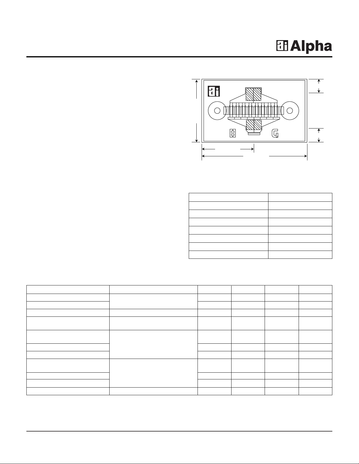
AFM08P2-000
Parameter Test Conditions Min. Typ. Max. Unit
Saturated Drain Current (I
DSS
)
VDS= 2 V, VGS= 0 V
175.0 265.0 360.0 mA
Transconductance (gm) 120.0 160.0 mS
Pinch-off Voltage (VP) VDS= 5 V, IDS= 2.0 mA 1.0 3.0 5.0 -V
Gate to Drain IGD= 800 µA 8.0 12.0 -V
Breakdown V oltage (V
bgd
)
Output Power at 1 dB 24.0 dBm
Compression (P
1 dB
)
Gain at 1 dB Compression (G
1 dB
)VDS= 5 V, IDS= 140 mA, F = 18 GHz 8.5 dB
Power Added Efficiency (ηadd) 20.0 %
Output Power at 1 dB 23.0 dBm
Compression (P
1 dB
)
Gain at 1 dB Compression (G
1 dB
) VDS= 5 V, IDS= 140 mA, F = 30 GHz 4.5 dB
Power Added Efficiency (ηadd) 10.0 %
Thermal Resistance (ΘJC) T
BASE
= 25°C 120.0 °C/W
Electrical Specifications at 25°C
0.395 mm
0.327 mm
Drain
Gate
0.655 mm
0.110 mm
0.110 mm
Characteristic Value
Drain to Source Voltage (VDS) 6 V
Gate to Source Voltage (VGS) -4 V
Drain Current (IDS) I
DSS
Gate Current (IGS) 2 mA
Total Power Dissipation (PT) 1.4 W
Storage Temperature (TST) -65 to +150°C
Channel Temperature (TCH) 175°C
Absolute Maximum Ratings
Chip thickness = 0.1 mm.
Page 2
2 Alpha Industries, Inc. [781] 935-5150 • Fax [617] 824-4579 • Email sales@alphaind.com • www.alphaind.com
Specifications subject to change without notice. 6/99A
Ka Band Power GaAs MESFET Chip AFM08P2-000
I-V
VDS (V)
l
DS
(mA)
0
0 1 2 3 54
60
120
180
240
300
-0.5 V
-1.0 V
-1.5 V
-2.0 V
-2.5 V
VGS = 0 V
Power Derating
0 50 100 150 200
Total Power Dissipation P
T
(W)
T
BASE
(˚C)
0
0.25
0.50
0.75
1.00
1.25
1.50
Typical Performance Data
Page 3

Ka Band Power GaAs MESFET Chip AFM08P2-000
Alpha Industries, Inc. [781] 935-5150 • Fax [617] 824-4579 • Email sales@alphaind.com • www.alphaind.com 3
Specifications subject to change without notice. 6/99A
Typical S-Parameters (VDS= 5 V, IDS= 140 mA)
Freq.
S
11
S
21
S
12
S
22
S
21
MAG
(GHz) Mag. Ang. Mag. Ang. Mag. Ang. Mag. Ang. k (dB) (dB)
2 0.922 -60.551 6.183 137.340 0.034 56.434 0.268 -53.648 0.287 15.824 22.614
3 0.886 -83.281 5.297 121.790 0.043 45.053 0.276 -72.863 0.352 14.481 20.875
4 0.858 -100.870 4.511 109.080 0.048 37.488 0.288 -86.395 0.448 13.085 19.764
5 0.846 -114.840 3.873 98.238 0.052 31.412 0.311 -97.508 0.490 11.760 18.726
6 0.833 -125.710 3.349 89.148 0.053 26.013 0.330 -105.520 0.595 10.499 18.038
7 0.830 -134.240 2.937 81.086 0.053 22.971 0.356 -111.660 0.660 9.359 17.440
8 0.827 -141.250 2.594 73.980 0.053 20.266 0.380 -117.070 0.751 8.280 16.937
9 0.826 -146.950 2.320 67.488 0.052 19.130 0.403 -121.090 0.835 7.309 16.522
10 0.826 -151.670 2.099 61.486 0.051 18.861 0.430 -124.530 0.911 6.439 16.156
11 0.826 -155.980 1.912 55.846 0.050 18.901 0.453 -127.950 0.985 5.630 15.794
12 0.826 -159.860 1.757 50.480 0.050 19.638 0.473 -131.070 1.054 4.896 14.032
13 0.826 -163.530 1.626 45.189 0.050 20.670 0.494 -134.390 1.107 4.220 13.123
14 0.827 -167.030 1.511 40.055 0.050 22.571 0.513 -137.680 1.168 3.584 12.349
15 0.827 -170.710 1.412 34.928 0.050 24.590 0.529 -141.300 1.222 2.994 11.674
16 0.828 -174.110 1.319 29.877 0.051 27.112 0.543 -144.910 1.256 2.402 11.108
17 0.827 -177.880 1.238 24.729 0.053 30.441 0.560 -149.190 1.266 1.851 10.612
18 0.830 178.710 1.157 19.509 0.054 29.130 0.579 -153.840 1.234 1.266 10.358
19 0.833 175.150 1.082 14.691 0.055 30.607 0.597 -158.560 1.237 0.681 9.976
20 0.834 171.690 1.006 9.473 0.057 29.948 0.615 -163.450 1.248 0.056 9.504
21 0.833 168.290 0.931 4.393 0.055 29.691 0.634 -168.500 1.375 -0.624 8.613
22 0.826 165.410 0.854 -0.449 0.054 28.928 0.654 -173.410 1.567 -1.375 7.567
23 0.824 164.040 0.774 -2.962 0.055 40.109 0.659 -176.480 1.814 -2.221 6.302
24 0.837 162.480 0.725 -5.707 0.061 41.107 0.685 -178.940 1.477 -2.796 6.695
25 0.841 160.910 0.675 -8.703 0.065 41.668 0.712 178.250 1.317 -3.419 6.786
26 0.851 160.020 0.632 -11.155 0.066 39.422 0.726 176.760 1.190 -3.980 7.168
27 0.861 158.950 0.593 -13.702 0.068 41.344 0.749 175.380 1.036 -4.532 8.244
28 0.869 157.730 0.561 -15.712 0.072 42.416 0.772 174.350 0.864 -5.026 8.934
29 0.873 157.100 0.530 -17.951 0.075 43.221 0.790 173.430 0.742 -5.517 8.481
30 0.876 156.340 0.504 -19.794 0.079 43.832 0.800 172.620 0.665 -5.945 8.038
31 0.878 155.500 0.482 -21.803 0.084 44.410 0.812 171.720 0.574 -6.330 7.595
32 0.879 154.510 0.463 -24.305 0.088 43.920 0.825 170.440 0.492 -6.693 7.197
33 0.875 153.200 0.444 -26.438 0.094 43.615 0.830 169.140 0.473 -7.046 6.729
34 0.875 151.820 0.429 -28.745 0.100 42.418 0.832 167.450 0.439 -7.342 6.340
35 0.873 149.570 0.415 -31.738 0.105 40.012 0.834 164.770 0.420 -7.631 5.960
36 0.870 147.470 0.398 -34.529 0.109 38.334 0.830 162.000 0.476 -8.004 5.642
37 0.869 145.350 0.382 -37.857 0.111 36.215 0.825 158.610 0.519 -8.358 5.349
38 0.866 142.450 0.361 -41.301 0.115 34.590 0.821 154.480 0.610 -8.842 4.983
39 0.865 139.560 0.342 -44.109 0.117 31.940 0.822 150.320 0.666 -9.319 4.655
40 0.859 137.290 0.303 -48.395 0.121 28.969 0.814 145.770 0.846 -10.363 3.978
S-Parameters include the effects of two 0.8 mil diameter bond wires, each 10 mil long, to each of the gate and drain terminals.
 Loading...