

Page 1
Alpha Industries, Inc. [781] 935-5150 • Fax [617] 824-4579 • Email sales@alphaind.com • www.alphaind.com 1
Specifications subject to change without notice. 6/99A
Ka Band Power GaAs MESFET Chip
Features
■ 22.5 dBm Output Power @ 18 GHz
■ High Associated Gain, 9 dB @ 18 GHz
■ High Power Added Efficiency, 23%
■ Broadband Operation, DC–40 GHz
■ 0.25 µm Ti/Pd/Au Gates
■ Passivated Surface
■ Through-Substrate Via Hole Grounding
Description
The AFM06P2-000 is a high performance power GaAs
MESFET chip having a gate length of 0.25 µm and a total
gate periphery of 600 µm.The device has e xcellent gain
and power performance through 40 GHz, making it
suitable for a wide range of commercial and military
applications in oscillator and amplifier circuits.It employs
Ti/Pd/Au gate metallization and surface passivation to
ensure a rugged, reliable part.Through-substrate via holes
are incorporated into the chip to facilitate low inductance
grounding of the source for improv ed high frequency and
high gain performance.
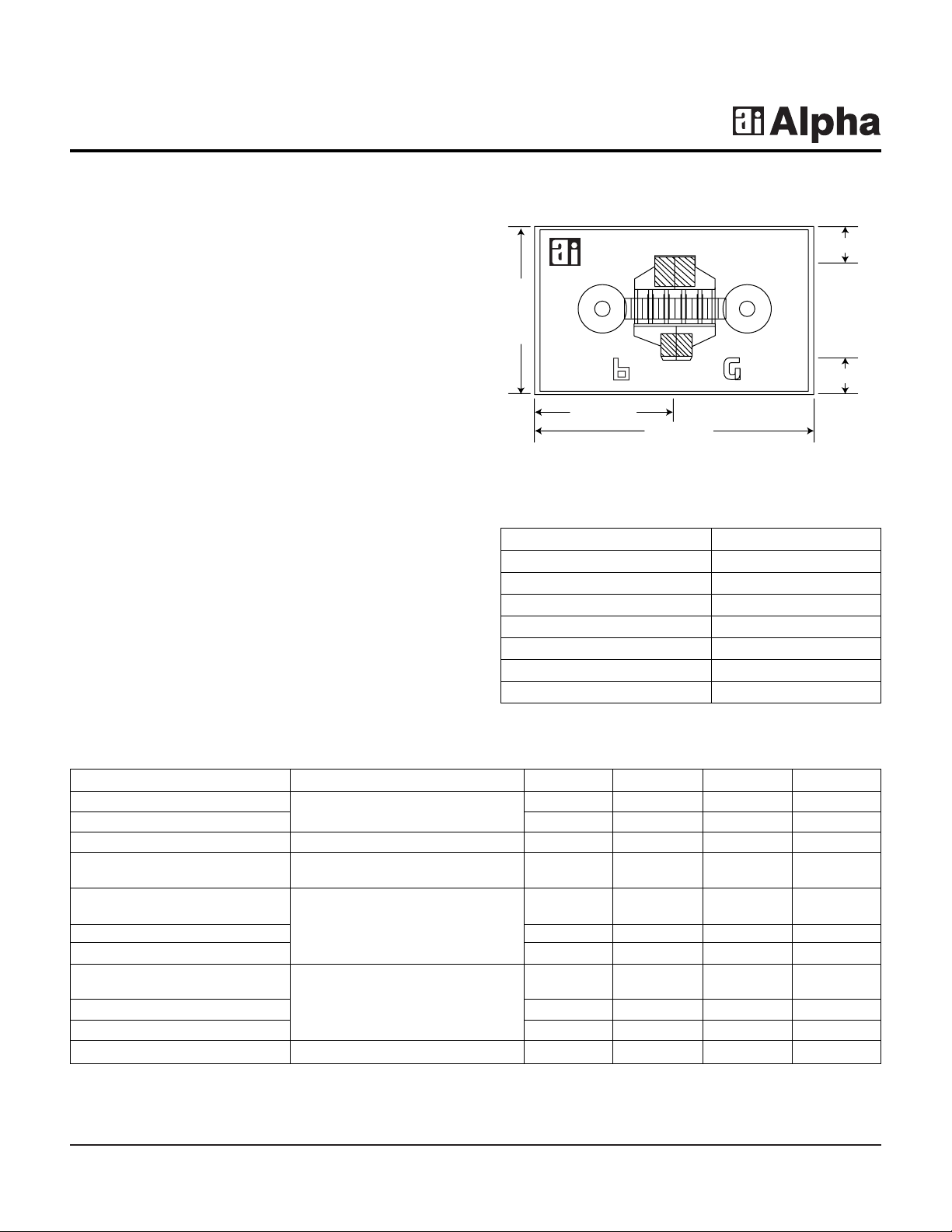
AFM06P2-000
Parameter Test Conditions Min. Typ. Max. Unit
Saturated Drain Current (I
DSS
)
VDS= 2 V, VGS= 0 V
130.0 200.0 270.0 mA
Transconductance (gm) 90.0 120.0 mS
Pinch-off Voltage (VP) VDS= 5 V, IDS= 1.5 mA 1.0 3.0 5.0 -V
Gate to Drain IGD= 600 µA 8.0 12.0 -V
Breakdown V oltage (V
bgd
)
Output Power at 1 dB 22.5 dBm
Compression (P
1 dB
)
Gain at 1 dB Compression (G
1 dB
)VDS= 5 V, IDS= 100 mA, F = 18 GHz 9.0 dB
Power Added Efficiency (ηadd) 23.0 %
Output Power at 1 dB 22.0 dBm
Compression (P
1 dB
)
Gain at 1 dB Compression (G
1 dB
) VDS= 5 V, IDS= 100 mA, F = 30 GHz 4.5 dB
Power Added Efficiency (ηadd) 15.0 %
Thermal Resistance (ΘJC) T
BASE
= 25°C 160.0 °C/W
Electrical Specifications at 25°C
0.395 mm
0.327 mm
Drain
Gate
0.655 mm
0.110 mm
0.110 mm
Characteristic Value
Drain to Source Voltage (VDS) 6 V
Gate to Source Voltage (VGS) -4 V
Drain Current (IDS) I
DSS
Gate Current (IGS) 1 mA
Total Power Dissipation (PT) 1.1 W
Storage Temperature (TST) -65 to +150°C
Channel Temperature (TCH) 175°C
Absolute Maximum Ratings
Chip thickness = 0.1 mm.
Page 2
2 Alpha Industries, Inc. [781] 935-5150 • Fax [617] 824-4579 • Email sales@alphaind.com • www.alphaind.com
Specifications subject to change without notice. 6/99A
Ka Band Power GaAs MESFET Chip AFM06P2-000
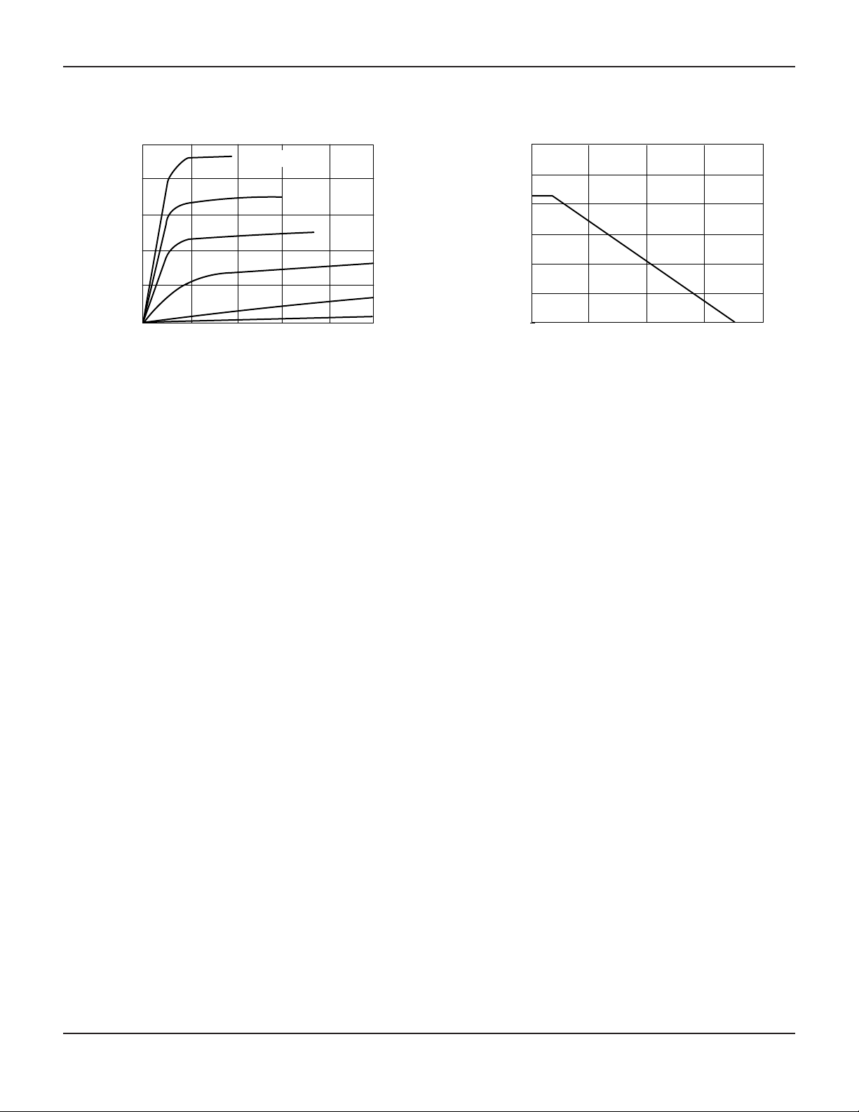
I-V
0
40
80
120
160
200
0 1 32 4 5
-0.5 V
-1.0 V
-1.5 V
-2.0 V
-2.5 V
VDS (V)
l
DS
(mA)
VGS = 0 V
Power Derating
0 50 100 150 200
Total Power Dissipation P
T
(W)
T
BASE
(˚C)
0
0.25
0.50
0.75
1.00
1.25
1.50
Typical Performance Data
Page 3

Ka Band Power GaAs MESFET Chip AFM06P2-000
Alpha Industries, Inc. [781] 935-5150 • Fax [617] 824-4579 • Email sales@alphaind.com • www.alphaind.com 3
Specifications subject to change without notice. 6/99A
Typical S-Parameters (VDS= 5 V, IDS= 120 mA)
Freq.
S
11
S
21
S
12
S
22
MAG
(GHz) Mag. Ang. Mag. Ang. Mag. Ang. Mag. Ang. k (dB)
2 0.943 -63.246 7.140 136.7680 0.031 53.027 0.340 -48.993 0.160 23.563
3 0.905 -86.534 6.080 120.3940 0.040 39.817 0.340 -66.574 0.240 21.828
4 0.876 -104.502 5.155 107.1240 0.045 29.754 0.346 -69.967 0.321 20.614
5 0.856 -118.460 4.405 96.0760 0.047 21.969 0.360 -90.387 0.403 19.690
6 0.843 -129.538 3.807 86.5660 0.048 15.797 0.368 -98.818 0.486 18.953
7 0.835 -138.558 3.328 68.1380 0.049 10.797 0.399 -105.932 0.569 18.348
8 0.830 -146.091 2.940 60.4900 0.048 6.688 0.423 -112.160 0.643 17.841
9 0.827 -152.503 2.619 63.4278 0.048 3.296 0.448 -117.776 0.693 1.410
10 0.825 -158.149 2.352 56.8180 0.046 0.510 0.473 -122.953 0.825 17.041
11 0.825 -163.140 2.125 50.5720 0.045 -1.735 0.499 -127.805 0.913 16.721
12 0.825 -167.642 1.931 44.6260 0.044 -3.476 0.524 -132.404 1.000 16.350
13 0.826 -171.656 1.672 38.9370 0.042 -4.733 0.549 -136.801 1.088 14.389
14 0.828 -175.561 1.615 33.4710 0.051 -5.512 0.564 -141.028 1.174 13.447
15 0.390 -169.110 1.485 28.2060 0.039 -5.818 0.598 -145.111 1.257 12.715
16 0.832 177.551 1.370 23.1220 0.038 -5.654 0.621 -149.064 1.336 12.105
17 0.834 167.439 1.267 18.2060 0.037 -5.028 0.643 -152.901 1.408 11.581
18 0.837 171.378 1.175 13.4470 0.036 -3.962 0.664 -156.631 1.471 11.124
19 0.839 168.496 1.091 8.8370 0.035 -2.492 0.685 -160.260 1.521 10.724
20 0.842 165.727 1.016 4.3690 0.034 -0.675 0.704 -163.695 1.556 10.373
21 0.845 163.057 0.947 0.0360 0.033 1.413 0.722 -167.239 1.574 10.066
22 0.847 160.476 0.884 -4.6500 0.033 3.678 0.740 -160.596 1.572 9.800
23 0.850 157.974 0.826 -8.2380 0.033 6.018 0.756 -173.869 1.551 9.574
24 0.852 155.545 0.773 -12.1880 0.034 8.333 0.722 -177.061 1.513 9.387
25 0.855 153.182 0.725 -16.0160 0.034 10.535 0.786 179.825 1.460 9.240
26 0.857 150.880 0.680 -19.7270 0.035 12.552 0.800 176.688 1.935 9.138
27 0.860 148.635 0.638 -23.3210 0.036 14.335 0.813 163.824 1.321 9.087
28 0.862 146.443 0.600 -26.8020 0.037 15.855 0.825 160.933 1.243 9.101
29 0.864 144.301 0.564 -30.1710 0.039 17.104 0.837 168.112 1.162 9.208
30 0.866 142.207 0.531 -33.4290 0.040 18.085 0.847 165.360 1.081 9.482
31 0.868 140.157 0.500 -36.5690 0.042 18.811 0.857 162.674 1.002 10.501
32 0.870 138.151 0.471 -39.6210 0.043 19.303 0.867 160.052 0.926 10.367
33 0.872 136.185 0.444 -42.5560 0.045 19.582 0.875 157.494 0.854 9.943
34 0.874 134.259 0.419 -45.3870 0.047 19.671 0.884 154.997 0.785 9.523
35 0.876 132.371 0.395 -48.1120 0.048 19.594 0.891 152.560 0.721 9.109
36 0.878 130.519 0.373 -50.7340 0.050 19.370 0.898 150.818 0.661 8.701
37 0.869 128.603 0.352 -53.2520 0.052 19.020 0.905 147.859 0.605 8.299
38 0.881 126.920 0.333 -55.6670 0.054 18.561 0.911 145.592 0.553 6.904
39 0.883 125.171 0.314 -567.9680 0.056 18.008 0.917 143.378 0.505 6.516
40 0.884 123.453 0.297 -60.1850 0.057 17.375 0.923 141.216 0.461 7.133
S-Parameters include the effects of two 0.8 mil diameter bond wires, each 10 mil long, to each of the gate and drain terminals.
 Loading...