

Page 1
EP
388
EP-RELAYS
HIGH V OL T AGE AND
CURRENT CUT-OFF
CAPACITY IN A
COMPACT PACKAGE
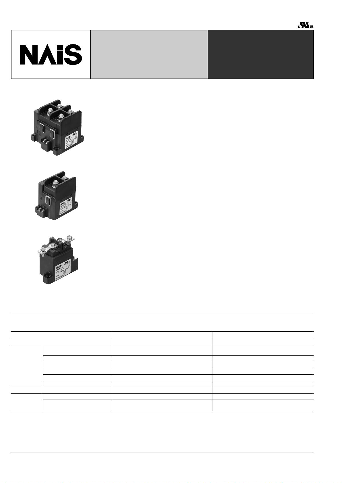
150A 2 Form A
150A 1 Form A
60A
FEATURES
• Control of large voltages and currents
The relays have a sealed construction
that is filled with a hydrogen gas compound, and use a permanent magnet to
establish a magnetic path for the arc. This
allows them to switch high-level DC voltages of up to 400V DC.
• Compact size and light weight
The capsule contact construction is filled
with a gas that has excellent thermal dissipation and insulation characteristics.
Because of this we have been able to reduce the contact gap to one tenth that of
conventional relays, and produce a compact and light design.
• No arc space is required: size including arc space 1/9 (compared to conventional contactors)
The arc is not exposed to the outside,
therefore, no arc space is not required.
• Safety construction
The arc is not exposed, therefore, the
contactor is explosion proof and intrinsically safe.
• Quiet: operation noise 1/4 (compared
to conventional contactors).
Along with the above-mentioned miniaturization, the operation noise has been reduced to 70dB, and, in addition, the
operation noise remains unchanged
when a current of 1000A or more is interrupted.
• High contact reliability
The contact part is hermetically sealed,
hence the contact resistance remains stable regardless of the ambient conditions.
• Mounting direction is not specified
The weight of the movable parts is light,
and also the restoring force is large,
hence the contactor is relatively unaffected by gravity.
• Line-up of indicator types (150A T ype
only)
1 Form A and 1 Form B types with indicators for detecting welding of the main contacts are available.
• 12 and 24V DC coil voltage types are
available.
• Screw terminal blocks for easy wiring.
SPECIFICATIONS
Contact
Notes:
Same specifications as the 12 V type.
#1
Condition: Nominal switching 100cycles, each cut off 2,500A
#2
Conditions: Varistor used for coil surge absorption. Note: if a diode is used the life will be lower.
Type 150A type 60A type
Arrangement 1 Form A, 2 Form A 1 Form A
Rating
Nominal switching capacity
(resistive load)
150A 400V DC
150A 277V AC
60A 400V DC
60A 277V AC
Short term current 300A (10min)(harness wire: 40mm
2
) 120A (15min)(harness wire: 15mm
2
)
Max. cut-off current 2,500A 300V DC (3 cycles)
#1
600A 300V DC (5 cycles)
Overload opening/closing rating 600A 400V DC (Min. 1,000 cycles) 180A 400V DC (Min. 100 cycles)
#2
Reverse cut-off current –200A 200V DC (Min. 500 cycles) –60A 200V DC (Min. 1,000 cycles)
#2
Contact voltage drop (Max.) 0.1V (When current [is 150A per 1] contact set) 0.1V (When current [is 60A per 1] contact set)
Nominal operating power 35W (Inrush, approx 0.1s) 5W ( Stable ) Max. 5W
Expected life
(min.
operations)
Mechanical 10
5
2 ×
10
5
Electrical
3 × 10
3
150A 400V DC
(L/R
&
1ms)
3 × 10
3
60A 400V DC
(L/R
&
1ms
#2
)
Page 2

EP
389
Characteristics
Remarks:
*
1
Measurement at same location as "Initial breakdown voltage" section.
*
2
Detection current: 10mA.
*
3
Nominal voltage applied to the coil, excluding bounce time.
*
4
Nominal voltage applied to the coil.
*
5
Half-wave pulse of sine wave: 11 ms; detection time: 10 µ s.
*
6
Half-wave pulse of sine wave: 6 ms.
*
7
Detection time: 10 µ s .
*
8
3 directions, each 4 hours.
*
9
Storage: Max.85 ° C 185 ° F.
Initial insulation resistance Min. 100 M Ω (at 500 V DC)*
1
Initial breakdown voltage
Between open contacts AC 2,500 Vrms for 1 min.*
2
Between contact and coil AC 2,500 Vrms for 1 min.*
2
Operate time (at 20 ° C) (at nominal voltage) Max. 50ms*
3
Reset time (without diode) (at 20 ° C) (at nominal voltage) Max. 30ms*
4
Shock resistance
Functional Min. 196 m/s
2
{20 G}*
5
Destructive Min. 490 m/s
2
{50 G}*
6
Vibration resistance
Functional 43 m/s
2
{4.4 G} 10 to 200Hz*
7
Destructive 43 m/s
2
{4.4 G} 10 to 200 Hz*
8
Conditions for operation,
transport and storage
(Not freezing and condensing at low
temperature)
Ambient temperature
–40 ° C to +80 ° C*
9
–40 ° F to +176 ° F
Humidity 5 to 85% R.H.
Unit weight
150 A 1 Form A: 600 g 21.16oz
150 A 2 Form A: 1,100 g 38.80oz
60 A: 340 g 12.00oz
Indicator ratings
Note: Indicator type is only available for the 150 A type.
Arrangement 1 Form A 1 Form B
Material Gold-clad
Rating(resistive load) 0.1 A 30 V DC
Contact resistance Max. 100 m Ω
TYPICAL APPLICATIONS
• UPS (uninterruptible power supplies)
• Solar power generation systems
• Unmanned transport carts
• Battery inspection and testing equipment
• Welding equipment
ORDERING INFORMATION
Product Name
EP
Contact arrangement Contact rating Coil voltage
1: 1 Form A
2: 2 Form A
5: 150A
6: 60A
0: without indicator contact
1: a contact (150A type only)
3: b contact (150A type only)
Indicator contact
arrangement
12: 12V DC
24: 24V DC
Ex. A EP 1 5 0 12
Page 3
EP
390
TYPES AND COIL DATA (at 20 ° C 68 ° F)
Note: *Same coil data as Indicator type. When using a DC power supply use one that has a leeway of at least 150% current capacity.
Part No.
Coil voltage,
V DC
Pick-up voltage,
V DC (max.)
(at 20 ° C)
Drop-out voltage,
V DC (min.)
(at 20 ° C)
Nominal coil
current, mA ( ± 10%)
(at 20 ° C)
Operating power, W
(12 V DC, at 20 ° C)
Max. allowable
voltage, V DC
AEP25012*
12 V DC 9 V DC 1 V DC
2.8 A
(at peak)*
35W(Inrush,
approx. 0.1S)
5W(Stable)
16 V DCAEP15012*
AEP16012 0.415 A Max. 5W
AEP25024*
24 V DC 18 V DC 2 V DC
1.9 A
(at peak)*
35W(Inrush,
approx. 0.1S)
Max. 5W (1 F orm A)
Max. 6W (2 F orm A)
32 V DC
AEP15024*
2.2 A
(at peak)*
AEP16024 0.208 A Max. 5W
Packing quantity
Types Inner Outer
150A 2 Form A 1pc. 5pcs.
150A 1 Form A 1pc. 10pcs.
60A 1 Form A 1pc. 20pcs.
SPARE PARTS
Installing parts Part No. Packing Quantity
M8 nut with washer for
150A type
AEV801 2pcs.
M5 screw for 60A type AEV802 2pcs.
M4 screw for 30A type AEV803 2pcs.
Bus bar for 60A type AEV804 1pc.
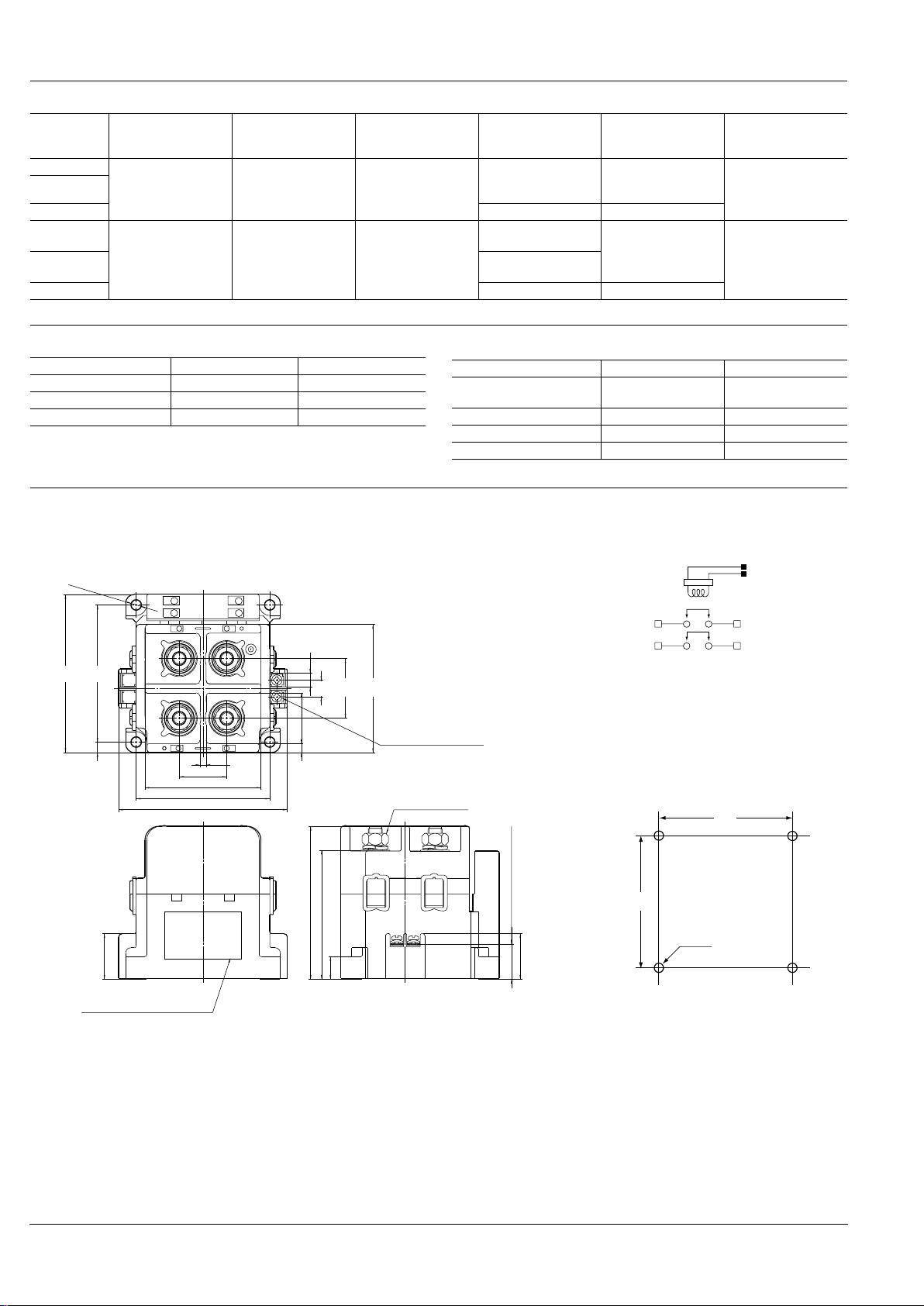
DIMENSIONS
150A 2 Form A
3.5
.138
27.0 1.063
66.0 2.598
96.0 3.780
±0.2
76.0
±.008
2.992
5
.197
29.0
1.142
7.7
.303
Coil input terminal (M3.5)
5 terminal: input (+) side
6 terminal: input (–) side
6
.236
26.0
1.024
Plate (Part No., rating,
schematic and Lot No.)
20.0 .787
(terminal height)
26.0
1.024
13.0
.512
73.5 2.894
(terminal height)
87.1
3.429
M8 nut; AEV801
3
-
+
1
4
2
-
+
3
-
4
+
6
7
8
9
9
X
Y
Z
1
9
2
3
4
5
65
2
-
+
1
87
4- 5.5
φ
±0.1
4- .217
φ
±.004
±0.2
78.0
±.008
3.071
90.0
3.543
9.5
.374
34.0
1.339
73.0
2.874
Schematic (TOP VIEW)
Mounting dimensions
6: Coil (–)
5: Coil (+)
2–
4+
1+
3–
Both input and load sides have polarities (+) and (–).
76
2.992
4- .217
φ
4- 5.5
φ
78
3.071
General tolerance:
less than 10 .394 ± 0.3 ± .012
10 .394 to 50 1.969 ± 0.6 ± .024
more than 50 1.969 ± 1.0 ± .039
mm inch
Page 4

EP
391
150A 2 Form A (Indicator Type)
3.5
.138
27.0 1.063
66.0 2.598
96.0 3.780
±0.2
76.0
±.008
2.992
5
.197
29.0
1.142
26.0
1.024
13.0
.512
87.1
3.429
3
+
1
4
2
-
+
3
-
4
+
6
7
8
9
9
X
Y
Z
1
9
2
3
4
5
65
2
-
+
1
87
9.5
.374
7.7
.303
6
.236
78.0
±0.2
3.071
±.008
90.0
3.543
26.0
1.024
Coil input terminal (M3.5)
5 terminal: input (+) side
6 terminal: input (–) side
Plate (Part No., rating,
schematic and Lot No.)
20.0 .787
(terminal height)
20.0 .787
(terminal height)
73.5 2.894
(terminal height)
M8 nut; AEV801
4- 5.5
φ
±0.1
4- .217
φ
±.004
Indicator input
terminal (M3.5)
7 terminal: NO or NC
8 terminal: COM
34.0
1.339
73.0
2.874
Schematic (TOP VIEW)
1 Form A
1 Form B
Mounting dimensions
6: Coil (–)
5: Coil (+)
8: Indicator: COM
7: Indicator: NO
2–
4+
1+
3–
Both input and load sides have polarities (+) and (–).
2–
4+
1+
3–
Both input and load sides have polarities (+) and (–).
6: Coil (–)
5: Coil (+)
8: Indicator: COM
7: Indicator: NC
76
2.992
4- .217
φ
4- 5.5
φ
78
3.071
General tolerance:
less than 10 .394 ± 0.3 ± .012
10 .394 to 50 1.969 ± 0.6 ± .024
more than 50 1.969 ± 1.0 ± .039
150A 1 Form A
3.5
.138
27.0 1.063
64.0 2.520
±0.2
76.0
±.008
2.992
94.0 3.701
19.5
.768
56.0
2.205
7.7
.303
9.5
.374
10.8
.425
6
.236
26.0
1.024
13.0
.512
87.1
3.429
M8 nut; AEV801
21.0
.827
1
+
2
-
1
+
-
2
56
5
6
7
8
9
X
Y
4
3
2
1
Z
99
87
Coil input terminal (M3.5)
5 terminal: input (+) side
6 terminal: input (–) side
Plate (Part No., rating,
schematic and Lot No.)
20.0 .787
(terminal height)
73.5 2.894
(terminal height)
2- 5.5
φ
±0.1
2- .217
φ
±.004
±0.2
44.0
±.008
1.732
29.0
1.142
Schematic (TOP VIEW)
Mounting dimensions
6: Coil (–)
5: Coil (+)
2–1+
Both input and load sides have polarities (+) and (–).
76
2.992
2- .217
φ
2- 5.5
φ
44
1.732
General tolerance:
less than 10 .394 ± 0.3 ± .012
10 .394 to 50 1.969 ± 0.6 ± .024
more than 50 1.969 ± 1.0 ±.039
mm inch
Page 5

EP
392
150A 1 Form A (Indicator Type)
3.5
27.0
64.0
±0.2
76.0
94.0
7.7
.303
9.5
.374
10.8
.425
6
.236
26.0
1.024
13.0
.512
87.1
3.429
1
+
2
-
1
+
-
2
Z
1
3
2
9
4
5
6
7
8
9
X
Y
9
65
21.0
.827
(
9.5
)
(
.374
)
87
Coil input terminal (M3.5)
5 terminal: input (+) side
6 terminal: input (–) side
Plate (Part No., rating,
schematic and Lot No.)
20.0 .787
(terminal height)
73.5 2.894
(terminal height)
2- 5.5
φ
±0.1
2- .217
φ
±.004
Indicator input
terminal (M3.5)
7 terminal: NO or NC
8 terminal: COM
M8 nut; AEV801
17.8
.701
19.5
.768
±0.2
44.0
±.008
1.732
29.0
1.142
56.0
2.205
15.0 .591
(terminal height)
Schematic (TOP VIEW)
1 Form A type
1 Form B type
Mounting dimensions
6: Coil (–)
5: Coil (+)
2–1+
Both input and load sides have polarities (+) and (–).
8: Indicator: COM
7: Indicator: NO
6: Coil (–)
5: Coil (+)
2–1+
Both input and load sides have polarities (+) and (–).
8: Indicator: COM
7: Indicator: NC
76
2.992
2- .217
φ
2- 5.5
φ
44
1.732
General tolerance:
less than 10 .394 ±0.3 ±.012
10 .394 to 50 1.969 ±0.6 ±.024
more than 50 1.969 ±1.0 ±.039
60A
2.5 .098
(17.9) (.705)
45.0 1.772
49.0 1.929
61.0
±0.2
2.402
±.008
76.0 2.992
13
.512
±0.2
26.0
±.008
1.024
30.2
1.189
38.0
1.496
7.7
.303
9.5
.374
6.55
.258
Coil input terminal (M3.5)
M4 screw: AEV803 (built-in)
63.9 2.516
79.9 3.146
M5 screw: AEV802
AEV804 (built-in)
Bus bar (15sq)
:
13.0
.512
71.0
2.795
26.0
1.024
+-
21
56
2- 5.5
φ
±0.1
2- .217
φ
±.004
Plate (Part No., rating,
schematic and Lot No.)
20.0 .787
(terminal height)
62.0 2.441
(terminal height)
Schematic (TOP VIEW)
Mounting dimension
6: Coil
5: Coil
2–1+
Load side has polarities (+) and (–).
61
2.402
26
1.024
2- .217
φ
2- 5.5
φ
General tolerance:
less than 10 .394 ±0.3 ±.012
10 .394 to 50 1.969 ±0.6 ±.024
more than 50 1.969 ±1.0 ±.039
mm inch
Page 6

EP
393
REFERENCE DATA
1-(1) Ambient temperature characteristics
(150 A type)
Sample: AEP15012, 3pcs
1-(2) Ambient temperature characteristics
Sample:AEP16012, 3pcs
2. Max. switching capacity
x
-
x
-
Pick up
voltage
Variation
ratio, %
Drop out
voltage
Ambient
temperature, °C °F
10
8
6
4
2
-40
-40
-20
-4
20
68
-6
-2
-4
-8
-10
60
110
40
74
80
146
0
32
x
-
x
-
40
30
20
10
-40
-40
-20
-4
20
68
-30
-10
-20
-40
60
110
40
74
80
146
0
32
Pick up
voltage
Variation
ratio, %
Drop out
voltage
Ambient
temperature °C °F
Contact voltage, V
Contact current, A
101
100 1000
1000
100
10
1
150A type
DC, AC 400V resistive load
60A type
DC, AC 400V resistive load
3. Switching life curve 4. Cut-off life curve 5. Carrying performance curve
Contact current, A
Life (×10
3
cycle)
10
100 1000
100
10
1
150A type
DC, AC 400V resistive load
60A type
DC, AC 400V resistive load
Cut-off current, A
100
1000
10000
1000
10
100
1
150A type
DC400V resistive load
60A type
DC400V resistive load
Life (cycle)
Carrying current, A
10
100 1000
10
5
10
4
10
100
1000
150A type
(Electric cable 40mm
2
)
60A type
(Electric cable 15mm
2
)
Time (sec)
NOTES
1. When installing the rela y , al ways use
washers to prevent loosening of the
screws.
Tighten each of the screws within the rated ranges given below. Exceeding the
maximum torque may result in breakage.
Mounting is possible in either direction.
• M8 screw (150 A main terminal): 8 to 10
N·m
• M5 screw (150 A, 60 A main unit mounting section): 2.5N·m to 3.6N·m
• M4 screw (60 A main terminal): 1.8 to
2.7 N·m
• M3.5 screw (Input terminal): 0.84 to 1.2
N·m
2. The coils (150 A type) and contacts
(60 A, 150 A) of the relay are polarized,
so follow the instructions in the connection schematic when connecting
the coils and contacts.
Type 150 A has contains a reverse surge
voltage absorption circuit;
therefore a surge protector is not needed.
We recommend installing a surge protector varistor (ZNR) for the 60 A types. A void
using a diode as this may result in decreased cut-off capability.
3. As a general rule, do not use a rela y
if it has been dropped.
4. Avoid mounting the relay in strong
magnetic fields (near a transformer or
magnet) or close to an object that radiates heat.
5. Electrical life
This relay is a high-voltage direct-current
switch. In its final breakdown mode, it ma y
lose the ability to provide the proper cutoff. Theref ore, do not exceed the indicated
switching capacity and life. (Please treat
the relay as a product with limited life and
replace it when necessary.)
In the event that the relay loses cut-off
ability, there is a possibility that burning
may spread to surrounding parts, so configure the layout so that the power is
turned off within one second.
6. Permeation life of internal gas
This relay uses a hermetically encased
contact (capsule contact) with gas inside.
The gas has a permeation life that is affected by the temperature inside the capsule contact (ambient temperature +
temperature rise due to flow of electrical
current). For this reason, make sure the
ambient operating temperature is between –40 and 80°C –40 and +176°F, and
the ambient storage temperature is between –40 and 85°C –40 and +185°F.
7. The case is designed so that it will
not come off with normal handling.
If you remove the case, the relay will not
function as intended, and its performance
cannot be guaranteed.
Page 7

EP
394
8. If the power is turned off and then
immediately on after applying the rated
voltage (current) continuously to the
relay's coil and contact, the resistance
of the coil will increase due to a rise in
the coil temperature. This causes the
pick-up voltage to rise, and possibly
exceed the rated pick-up voltage. In
these circumstances, take measures
such as reducing the load current, limiting the duration of current flow, and
applying a coil voltage higher than the
rated operating voltage (quick start).
9. The coil must only be supplied with
its rated voltage. The v oltage waveform
supplied to the coil should be rectangular.
10. Take steps to ensure that voltages
that exceed the maximum allowed v oltage for a coil are never continuously
applied.
11. Take steps to ensure that the rated
voltage and current values for the contacts are never exceeded.
12. The rated control capacity and life
are given as guides.
The contact life is heavily influenced by
the type of load and other related conditions, and these factors must be giv en due
consideration when using the relay.
13. Main contact ratings in the ratings
apply to when there is a resistive load.
14. If you are using an inductive load (L
load) such that L/R > 1 ms, add surge
protection in parallel with the inductive
load. If this is not done, the electrical
life will decrease and cut-off failure
may occur.
15. When using the 150 A type, mount
it as far away as possible from amateur
wireless transmitters or devices that
may generate large surges. To prevent
malfunctioning due to high emission
levels, it may be neccessary to take
measures for E.M.I., such as adding a
line noise filter or an electromagnetic
shield.
16. Since coil current control is performed, a slight amount of superimposed line noise may be generated in
the input line system. If this noise must
be removed, install a line noise filter.
17. Be careful that foreign matter and
oils do not stick to the main terminal
part. It is likely to cause a terminal part
to give off unusual heat. Use the following specifications for the harness
bus bar that the relay connects to:
• 150A type: nominal cross sectional area:
min. 38mm
2
.
• 60A type: nominal cross sectional area:
min. 14mm
2
.
18. A void excessive load applied to the
terminal in case of installing such as a
bus bar etc., because it might give bad
influence to the opening and closing
performance.
• M8 screw terminal (150A main terminal
part)
Terminal pulling up strength ; Max.100N per
terminal
The up-down rotation torque applied to the
terminal ; Max.15N·m
19. For AC cut-off there is no contact
polarity, but confirm the electrical life
using the actual load. In the case of DC
cut-off the contacts have polarity, so
take due care.
9/1/2000 All Rights Reserved, © Copyright Matsushita Electric Works, Ltd.
Go To Online Catalog
 Loading...