

Page 1
SALEM® Three-Phase
a
FEATURES
IEC 687, Class 0.5 and Class 0.2 Accuracy
ANSI C12.1
IEC 1268, Requirements for Reactive Power
Configurable as Import/Export or Import Only
Simultaneous Measurement of:
Active Power and Energy—Import and Export
Reactive Power and Energy
Apparent Power
Power Factor for Individual Phases and Total Frequency
RMS Voltage for All Phases
RMS Current for All Phases
Harmonic Analysis for Voltage and Current
All Odd Harmonics up to 21st Order
Interface with a General Purpose Microcontroller
User-Friendly Calibration of Gain Offset and Phase and
Nonlinearity Compensation on CTs (Patent Pending)
Two Programmable Output E-Pulses
Programmable E-Pulse Constant from 1,000 Pulses/kWh
to 20,000 Pulses/kWh
15 kHz Sampling Frequency
Tamper-Proof Metering
Single 5 V Supply
SMPS
RESISTOR
BLOCK
CT
CT
CT
Electronic Energy Meter
ADSST-EM-3035
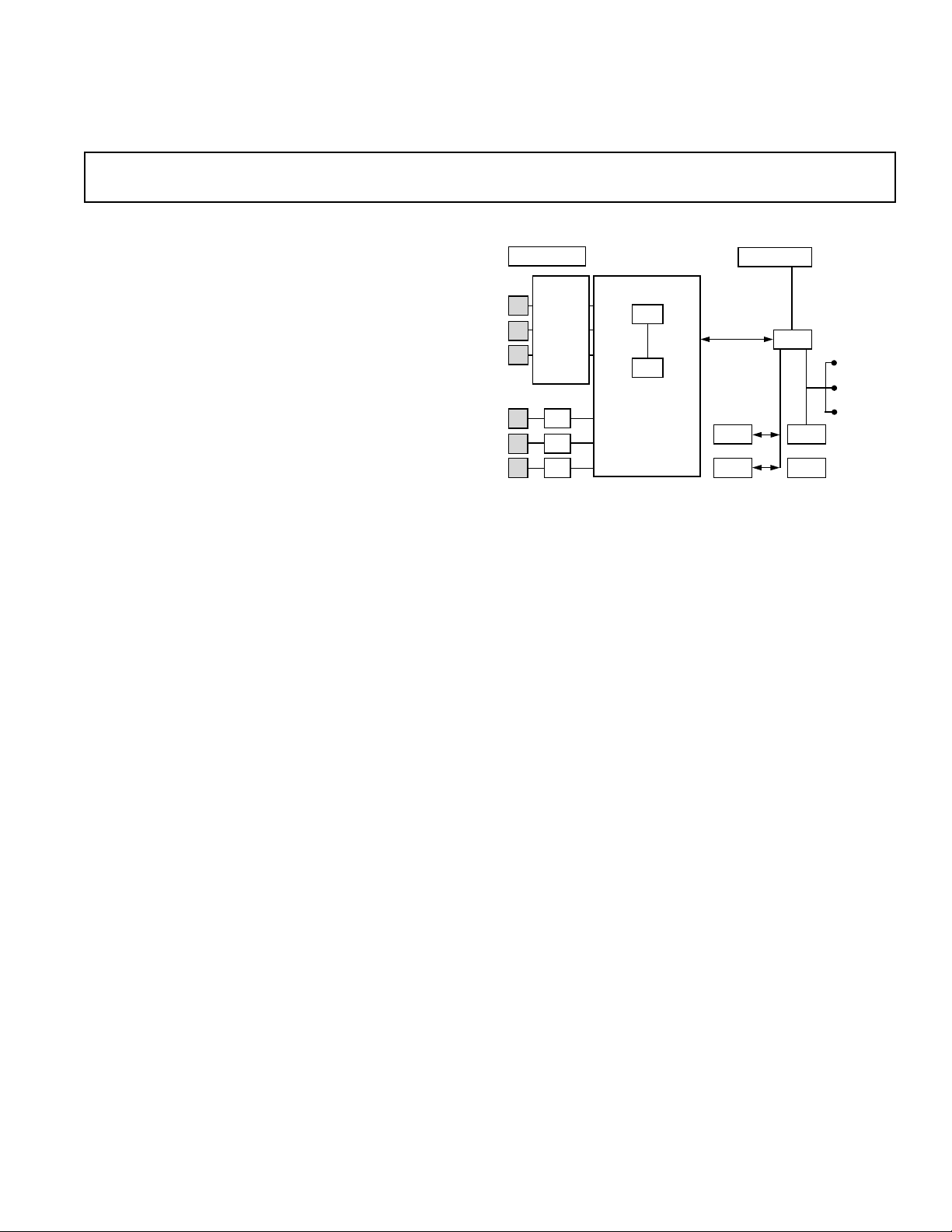
FUNCTIONAL BLOCK DIAGRAM
LCD DISPLAY
DSP
ADC
ADSST-EM-3035
CHIPSET
SPI BUS
FLASH
RTC
C
BUTTONS
OPTO
RS-232
GENERAL DESCRIPTION
The ADSST-EM-3035 Chipset consists of a fast and accurate
6 channel, 16-bit sigma-delta analog-to-digital converter
ADSST-73360AR (ADC), an efficient digital signal processor
ADSST-2185KST-133 (DSP), and Metering Software. The
ADC and DSP are interfaced together to simultaneously acquire
voltage and current samples on all the three phases and perform
mathematically intensive computations to accurately
calculate
the Powers, Energies, Instantaneous Quantities, and Harmonics.
The chipset could be interfaced to any general-purpose microprocessor to develop state of the art polyphase or Tri-vector energy
metering solution in accordance with IEC 1036, IEC 687, or
ANSI C12.1.
All calibrations are done in digital domain and no trimming
potentiometers are required.
SALEM is a registered trademark of Analog Devices, Inc.
REV. 0
Information furnished by Analog Devices is believed to be accurate and
reliable. However, no responsibility is assumed by Analog Devices for its
use, nor for any infringements of patents or other rights of third parties that
may result from its use. No license is granted by implication or otherwise
under any patent or patent rights of Analog Devices.
One Technology Way, P.O. Box 9106, Norwood, MA 02062-9106, U.S.A.
Tel: 781/329-4700 www.analog.com
Fax: 781/326-8703 © Analog Devices, Inc., 2002
Page 2
ADSST-EM-3035
ADSST-2185KST-133 (DSP) SPECIFICATION
FEATURES
30 ns Instruction Cycle 33 MIPS Sustained Performance
Single-Cycle Instruction Execution
Single-Cycle Context Switch
Three-Bus Architecture Allows Dual Operand Fetches
in Every Instruction Cycle
Multifunction Instructions
Power-Down Mode Featuring Low CMOS Standby Power
Dissipation with 100 Cycle Recovery from Power-Down
Condition
Low Power Dissipation in Idle Mode
ADSP-2100 Family Code Compatible, with Instruction
Set Extensions
40 kBytes of On-Chip RAM, Configured as
8 KWords On-Chip Program Memory RAM and
8 KWords On-Chip Data Memory RAM
Dual Purpose Program Memory for Both Instruction
and Data Storage
Independent ALU, Multiplier/Accumulator, and Barrel
Shifter Computational Units
Two Independent Data Address Generators
Powerful Program Sequencer Provides Zero Overhead
Looping Conditional Instruction Execution
Programmable 16-Bit Interval Timer with Prescaler
100-Lead TQFP
16-Bit Internal DMA Port for High Speed Access to On-
Chip Memory (Mode Selectable)
4 MBytes Byte Memory Interface for Storage of Data
Tables and Program Overlays
8-Bit DMA to Byte Memory for Transparent Program and
Data Memory Transfers (Mode Selectable)
I/O Memory Interface with 2048 Locations Supports
Parallel Peripherals (Mode Selectable)
Programmable Memory Strobe and Separate I/O
Memory Space Permits Glueless System Design
(Mode Selectable)
Programmable Wait State Generation
Two Double-Buffered Serial Ports with Companding
GENERAL DESCRIPTION
The ADSST-2185KST-133 is a single-chip microcomputer
optimized for digital signal processing (DSP) and other high
speed numeric processing applications.
The ADSST-2185KST-133 combines the ADSP-2100 family
base architecture (three computational units, data address
generators, and a program sequencer) with two serial ports, a
16-bit internal DMA port, a byte DMA port, a programmable
timer, Flag I/O, extensive interrupt capabilities, and on-chip
program and data memory.
The ADSST-2185KST-133 integrates 40 kBytes of on-chip
memory configured as 8 Kwords (24-bit) of program RAM and
8 Kwords (16-bit) of data RAM. Power-down circuitry is also
provided to meet the low power needs of battery operated portable
equipment. The ADSST-2185KST-133 is available in a 100-lead
TQFP package.
In addition, the ADSST-2185KST-133 supports instructions
that include bit manipulations, bit set, bit clear, bit toggle, bit
test new ALU constants, new multiplication instruction (x squared),
biased rounding, result free ALU operations, I/O memory transfers, and global interrupt masking for increased flexibility.
Fabricated in a high speed, double metal, low power, CMOS
process, the ADSST-2185KST-133 operates with a 25 ns
instruction cycle time. Every instruction can execute in a single
processor cycle.
The ADSST-2185KST-133’s flexible architecture and comprehensive instruction set allow the processor to perform
multiple operations in parallel. In one processor cycle, the
ADSST-2185KST-133 can:
•
•
•
•
•
•
Hardware and Automatic Data Buffering
Automatic Booting of On-Chip Program Memory from
Byte-Wide External Memory, e.g., EPROM, or through
Internal DMA Port
Six External Interrupts
13 Programmable Flag Pins Provide Flexible System Signaling
UART Emulation through Software SPORT Reconfiguration
ICE-Port Emulator Interface Supports Debugging in Final Systems
Generate the next program address
Fetch the next instruction
Perform one or two data moves
Update one or two data address pointers
Perform a computational operation
This takes place while the processor continues to:
Receive and transmit data through the two serial ports
Receive and/or transmit data through the internal DMA port
Receive and/or transmit data through the byte DMA port
Decrement timer
POWER-DOWN
DATA ADDRESS
GENERATORS
DAG 2
DAG 1
ARITHMETIC UNITS
ALU
MAC
ADSP-2100 BASE
ARCHITECTURE
PROGRAM
SEQUENCER
PROGRAM MEMORY ADDRESS
DATA MEMORY ADDRESS
PROGRAM MEMORY DATA
DATA MEMORY DATA
SHIFTER
CONTROL
MEMORY
16K 24
PROGRAM
MEMORY
SERIAL PORTS
16K 16
DATA
MEMORY
SPORT 1SPORT 0
PROGRAMMABLE
I/O
AND
FLAGS
TIMER
FULL MEMORY
MODE
EXTERNAL
ADDRESS
BUS
EXTERNAL
DATA
BUS
BYTE DMA
CONTROLLER
OR
EXTERNAL
DATA
BUS
INTERNAL
DMA
PORT
HOST MODE
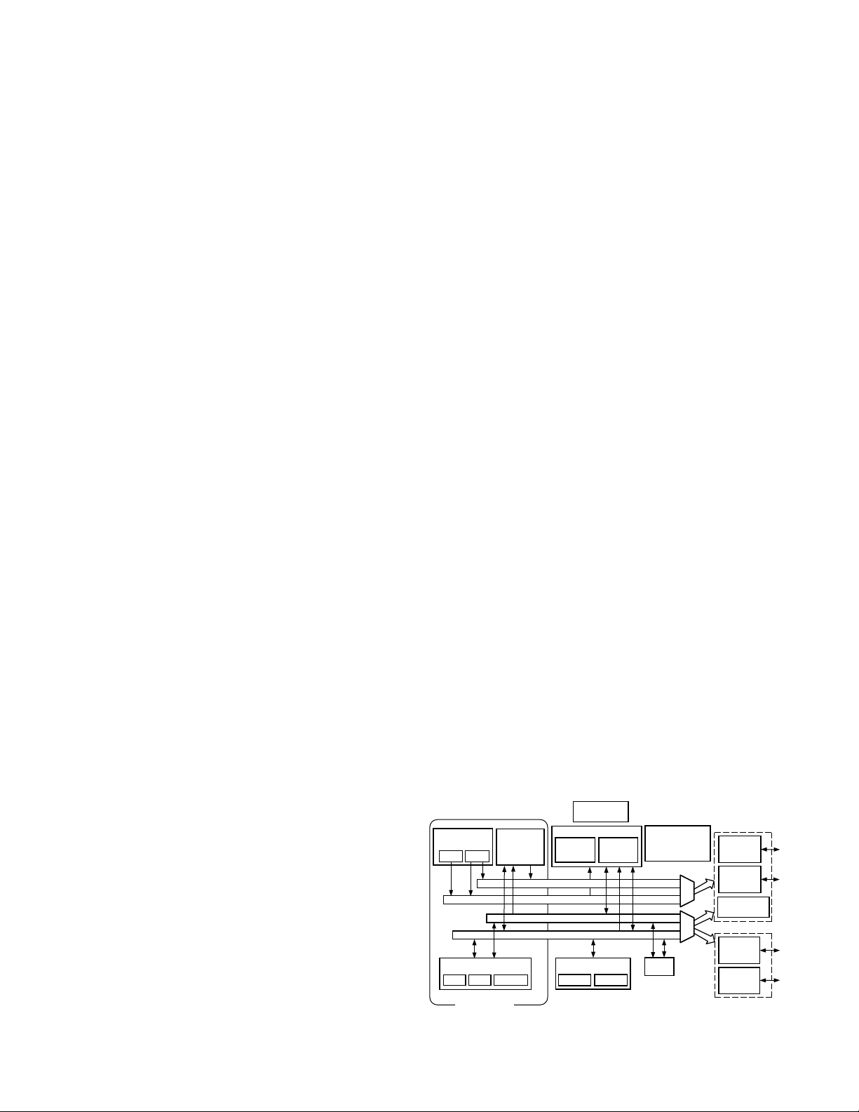
Figure 1. Functional Block Diagram
–2–
REV. 0
Page 3

ADSST-EM-3035
ARCHITECTURE OVERVIEW
The ADSST-2185KST-133 instruction set provides flexible
data moves and multifunction (one or two data moves with a
computation) instructions. Every instruction can be executed in
a single processor cycle. The ADSST-2185KST-133 assembly
language uses an algebraic syntax for ease of coding and readability. A comprehensive set of development tools supports
program development.
Figure 1 is an overall block diagram of the ADSST-2185KST-133.
The processor contains three independent computational units:
the ALU, the multiplier/accumulator (MAC), and the shifter.
The computational units process 16-bit data directly and have
provisions
performs a standard set of arithmetic and logic operations; division
primitives are also supported. The MAC performs single-cycle
multiply, multiply/add and multiply/subtract operations with 40
bits of accumulation. The shifter performs logical and arithmetic
shifts, normalization, denormalization and derive exponent
operations.
The shifter can be used to efficiently implement numeric format
control including multiword and block floating-point representations.
The internal result (R) bus connects the computational units
so the output of any unit may be the input of any unit on the
next cycle.
A powerful program sequencer and two dedicated data address
generators ensure efficient delivery of operands to these computational units. The sequencer supports conditional jumps,
subroutine calls, and returns in a single cycle. With internal loop
counters and loop stacks, the ADSST-2185KST-133 executes
looped code with zero overhead. No explicit jump instructions
are required to maintain loops.
Two data address generators (DAGs) provide addresses for simultaneous dual operand fetches from data memory and program memory.
Each DAG maintains and updates four address pointers. Whenever
the pointer is used to access data (indirect addressing),
modified by the value of one of four possible modify registers. A
length value may be associated with each pointer to implement
automatic modulo addressing for circular buffers.
Efficient data transfer is achieved with the use of five internal buses:
•
•
•
•
•
The two address buses (PMA and DMA) share a single external
address bus, allowing memory to be expanded off-chip, and the two
data buses (PMD and DMD) share a single external data bus.
memory space and I/O memory space also share the external buses.
Program memory can store both instructions and data, permitting
the ADSST-2185KST-133 to fetch two operands in a single cycle,
one from program memory and one from data memory. The
ADSST-2185KST-133 can fetch an operand from program
memory and the next instruction in the same cycle.
When configured in host mode, the ADSST-2185KST-133 has
a 16-bit Internal DMA port (IDMA port) for connection to
external systems. The IDMA port is made up of 16 data/address
pins and five control pins. The IDMA port provides transparent,
direct access to the DSP’s on-chip program and data RAM.
REV. 0
to support multiprecision computations. The ALU
it is post-
Program Memory Address (PMA) Bus
Program Memory Data (PMD) Bus
Data Memory Address (DMA) Bus
Data Memory Data (DMD) Bus
Result (R) Bus
Byte
An interface to low cost byte-wide memory is provided by the
Byte DMA port (BDMA port). The BDMA port is bidirectional
and can directly address up to four megabytes of external RAM
or ROM for off-chip storage of program overlays or data tables.
The byte memory and I/O memory space interface supports slow
memories and I/O memory-mapped peripherals with programmable
wait state generation. External devices can gain control of external
buses with bus request/grant signals (BR, BGH, and BG). One
execution mode (Go Mode) allows the ADSST-2185KST-133
to continue running from on-chip memory. Normal execution
mode requires the processor to halt while buses are granted.
The ADSST-2185KST-133 can respond to 11 interrupts.
There are up to six external interrupts (one edge-sensitive, two
level-sensitive, and three configurable) and seven internal interrupts generated by the timer, the serial ports (SPORTs), the
Byte DMA port, and the power-down circuitry. There is also a
master RESET signal. The two serial ports provide a complete
synchronous serial interface with optional companding in hardware and a wide variety of framed or frameless data transmit
and receive modes of operation.
Each port can generate an internal programmable serial clock or
accept an external serial clock.
The ADSST-2185KST-133 provides up to 13 general purpose
flag pins. The data input and output pins on SPORT1 can be
alternatively configured as an input flag and an output flag. In
addition, eight flags are programmable as inputs or outputs, and
three flags are always outputs.
A programmable interval timer generates periodic interrupts. A
16-bit count register (TCOUNT) decrements every n processor
cycle, where n is a scaling value stored in an 8-bit register (TSCALE).
When the value of the count register reaches zero, an interrupt is
generated and the count register is reloaded from a 16-bit period
register (TPERIOD).
Serial Ports
The ADSST-2185KST-133 incorporates two complete synchronous
serial ports (SPORT0 and SPORT1) for serial communications
and multiprocessor communication.
Here is a brief list of the capabilities of the ADSST-2185KST-133
SPORTs. For additional information on Serial Ports, refer to
the ADSP-2100 Family User’s Manual, Third Edition.
•
SPORTs are bidirectional and have a separate, double-buffered
transmit and receive section.
•
SPORTs can use an external serial clock or generate their own
serial clock internally.
•
SPORTs have independent framing for the receive and transmit
sections. Sections run in a frameless mode or with frame synchronization signals internally or externally generated. Frame
sync signals are active high or inverted, with either of two
pulsewidths and timings.
•
SPORTs support serial data word lengths from 3 to 16 bits and
provide optional A-law and M-law companding according to
CCITT recommendation G.711.
•
SPORT receive and transmit sections can generate unique
interrupts on completing a data-word transfer.
•
SPORTs can receive and transmit an entire circular buffer of
data with only one overhead cycle per data-word. An interrupt
is generated after a data buffer transfer.
–3–
Page 4

ADSST-EM-3035
•
SPORT0 has a multichannel interface to selectively receive and
transmit a 24- or 32-word, time-division multiplexed, serial
bitstream.
•
SPORT1 can be configured to have two external interrupts
(IRQ0 and IRQ1) and the Flag In and Flag Out signals. The
internally generated serial clock may still be used in this
configuration.
Table I. Common-Mode Pins
Pin Descriptions
The ADSST-2185KST-133 is available in a 100-lead TQFP
package. To maintain maximum functionality and reduce package size and pin count, some serial ports, programmable flags,
interrupt and external bus pins have dual, multiplexed functionality. The external bus pins are configured during RESET only,
while serial port pins are software configurable during program
execution. Flag and interrupt functionality is retained concurrently on multiplexed pins. In cases where pin functionality is
reconfigurable, the default state is shown in plain text; alternate
functionality is shown in italics.
Pin Number Input/
Name(s) of Pins Output Function
RESET 1IProcessor Reset Input
BR 1IBus Request Input
BG 1OBus Grant Output
BGH 1OBus Grant Hung Output
DMS 1OData Memory Select Output
PMS 1O
Program Memory Select Output
IOMS 1OMemory Select Output
BMS 1OByte Memory Select Output
CMS 1OCombined Memory
Select Output
RD 1OMemory Read Enable Output
WR 1OMemory Read Enable Output
IRQ2+PF7
IRQL0+PF5 1 I Level-Sensitive
IRQL1+PF6
IRQE+PF4
1IEdge- or Level-Sensitive
Interrupt Request
Interrupt Requests
1ILevel-Sensitive
Interrupt
Requests
1IEdge-Sensitive
Interrupt Requests
1
1
1
1
PF3 1 I/O Programmable I/O Pin
PF2 (Mode C)
1IProgrammable I/O Pin Mode
Select Input-Checked only
During RESET
PF1 (Mode B)
1IMode Select Input-Checked
only During RESET
Pin Number Input/
Name(s) of Pins Output Function
PF0 (Mode A) 1 I Mode Select Input-Checked
only During RESET
CLKIN, 2 I Clock or Quartz Crystal Input
XTAL
CLKOUT 1 O Processor Clock Output
SPORT0 5 I/O Serial Port I/O Pins
SPORT1 5 I/O Serial Port I/O Pins
IRQ1:0 Edge- or Level-Sensitive
Interrupts
F1, F0 Flag In, Flag Out
2
PWD 1IPower-Down Control Input
PWDACK 1 O Power-Down Control Output
FL0, FL1, 3 O Output Flags
FL2
VDD 16 I VDD and GND
AND
GND
EX-Port 9 I/O For Emulation Use
NOTES
1
Interrupt/Flag pins retain both functions concurrently. If IMASK is set to enable
the corresponding interrupts, the DSP will vector to the appropriate interrupt
vector address when the pin is asserted, either by external devices or set as a
programmable flag.
2
SPORT configuration determined by the DSP System Control Register. Software
configurable.
–4–
REV. 0
Page 5
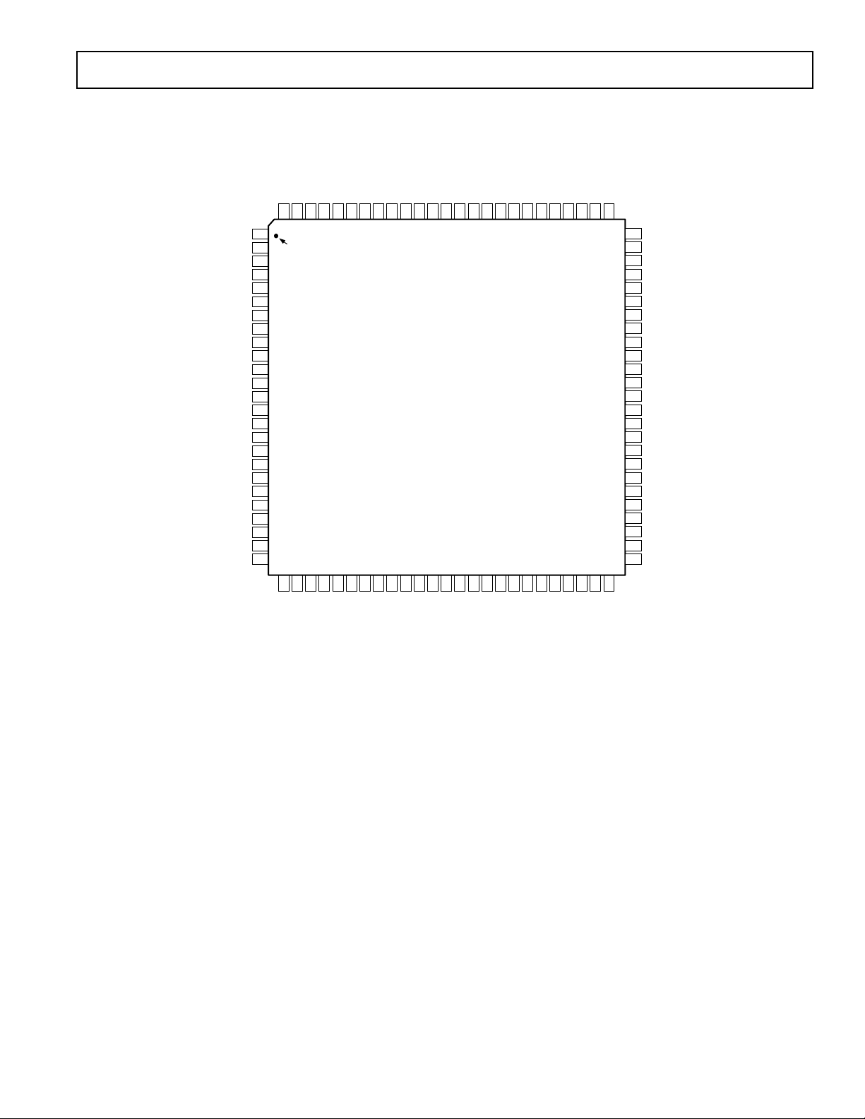
100-Lead TQFP Package Pinout
ADSST-EM-3035
A4/IAD3
A5/IAD4
GND
A6/IAD5
A7/IAD6
A8/IAD7
A9/IAD8
A10/IAD9
A11/IAD10
A12/IAD11
A13/IAD12
GND
CLKIN
XTAL
VDD
CLKOUT
GND
VDD
WR
RD
BMS
DMS
PMS
IOMS
CMS
A0
A3/IAD2
A2/IAD1
A1/IAD0
PWDACK
BGH
9998979695949392919089888786858483828180797877
100
1
PIN 1
2
IDENTIFIER
3
4
5
6
7
8
9
10
11
12
13
14
15
16
17
18
19
20
21
22
23
24
25
2728293031323334353637383940414243444546474849
26
DT0
GND
IRQL0+PF5
IRQL1+PF6
IRQ2+PF7
IRQE+PF4
PWD
GND
PF1 [MODE B]
PF0 [MODE A]
PF2 [MODE C]
VDD
ADSST-2185KST-133
TOP VIEW
(Not to Scale)
DR0
RFS0
VDD
SCLK0
DT1/FO
TFS0
PF3
TFS1/IRQ1
FL0
RFS1/IRQ0
FL1
FL2
GND
DR1/FI
D23
D22
SCLK1
ERESET
D20
D21
EMS
RESET
GND
EE
D19
ECLK
D18
D17
ELIN
ELOUT
D16
76
50
EINT
75
74
73
72
71
70
69
68
67
66
65
64
63
62
61
60
59
58
57
56
55
54
53
52
51
D15
D14
D13
D12
GND
D11
D10
D9
VDD
GND
D8
D7/IWR
D6/IRD
D5/IAL
D4/IS
GND
VDD
D3/IACK
D2/IAD15
D1/IAD14
D0/IAD13
BG
EBG
BR
EBR
REV. 0
–5–
Page 6
ADSST-EM-3035
System Interface
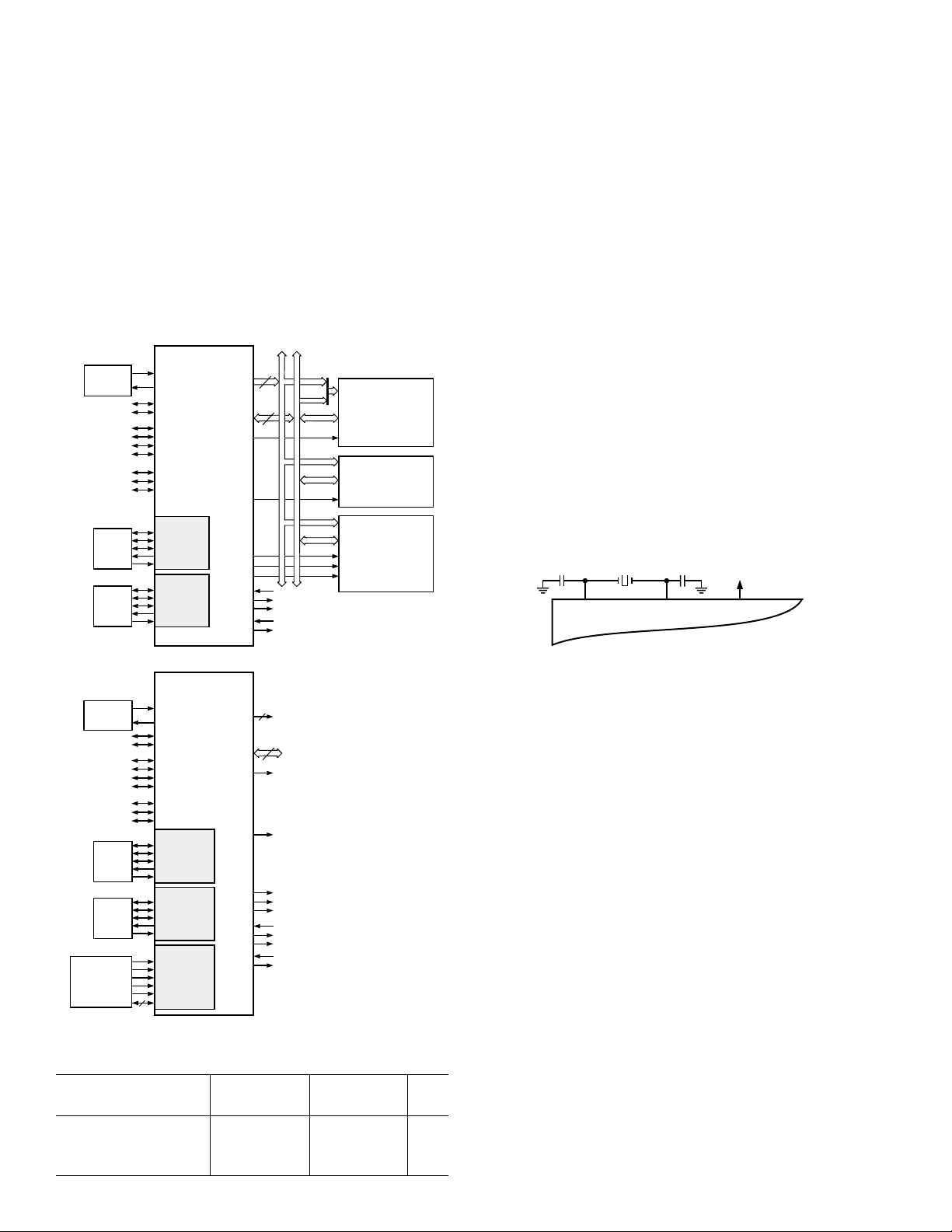
Figure 2 shows typical basic system configurations with the
ADSST-2185KST-133, two serial devices, a byte-wide EPROM
and optional external program and data overlay memories (mode
selectable). Programmable wait state generation allows the processor to connect easily to slow peripheral devices. The ADSST2185KST-133 also provides four external interrupts and two serial
ports, or six external interrupts and one serial port. Host Memory
Mode allows access to the full external data bus, but limits addressing to a single address bit (A0). Additional system peripherals can
be added in this mode through the use of external hardware to
generate and latch address signals.
FULL MEMORY MODE
ADSST-2185
1/2x CLOCK
OR
CRYSTAL
SERIAL
DEVICE
SERIAL
DEVICE
KST-133
CLKIN
XTAL
FL0–2
PF3
IRQ2/PF7
IRQE/PF4
IRQL0/PF5
IRQL1/PF6
MODE C/PF2
MODE B/PF1
MODE A/PF0
SPORT1
SCLK1
RFS1 OR IRQ0
TFS1 OR IRQ1
DT1 OR FO
DR1 OR FI
SPORT0
SCLK0
RFS0
TFS0
DT0
DR0
ADDR13–0
DATA23–0
BMS
IOMS
PMS
DMS
CMS
BGH
PWD
PWDACK
BR
BG
A
14
13–0
A0–A21
D
23–16
D
24
15–8
A
10–0
D
23–8
A
13–0
D
23–0
DATA
CS
ADDR
DATA
(PERIPHERALS)
2048 LOCATIONS
CS
ADDR
OVERLAY
MEMORY
DATA
PM SEGMENTS
DM SEGMENTS
BYTE
MEMORY
I/O SPACE
TWO 8K
TWO 8K
Clock Signals
Either a crystal or a TTL-compatible clock signal can clock the
ADSST-2185KST-133.
The CLKIN input cannot be halted, changed during operation,
or operated below the specified frequency during normal
operation. The only exception is while the processor is in the
power-down state. For additional information, refer to Chapter 9,
ADSP-2100 Family User’s Manual, Third Edition, for detailed
information on this power-down feature.
If an external clock is used, it should be a TTL-compatible signal
running at half the instruction rate. The signal is connected to the
processor's CLKIN input. When an external clock is used, the
XTAL input must be left unconnected.
The ADSST-2185KST-133 uses an input clock with a frequency
equal to half the instruction rate; a 20.00 MHz input clock
yields a 25 ns processor cycle (which is equivalent to 40 MHz).
Normally, instructions are executed in a single processor cycle.
All device timing is relative to the internal instruction clock rate,
which is indicated by the CLKOUT signal when enabled.
Because the ADSST-2185KST-133 includes an on-chip oscillator
circuit, an external crystal may be used. The crystal should be
connected across the CLKIN and XTAL pins, with two capacitors
connected as shown in Figure 3. Capacitor values are dependent
on crystal type and should be specified by the crystal manufacturer.
A parallel-resonant, fundamental frequency,
microprocessor-
grade crystal should be used.
CLKIN XTAL CLKOUT
DSP
HOST MEMORY MODE
ADSST-2185
1/2x CLOCK
OR
CRYSTAL
SERIAL
DEVICE
SERIAL
DEVICE
SYSTEM
INTERFACE
OR
CONTROLLER
CLKIN
XTAL
FL0–2
PF3
IRQ2/PF7
IRQE/PF4
IRQL0/PF5
IRQL1/PF6
MODE C/PF2
MODE B/PF1
MODE A/PF0
SCLK1
RFS1 OR IRQ0
TFS1 OR IRQ1
DT1 OR FO
DR1 OR FI
SCLK0
RFS0
TFS0
DT0
DR0
IRD/D6
IWR/D7
IS/D4
IAL/D5
IACK/D3
IAD15–0
16
KST-133
SPORT1
SPORT0
IDMA PORT
ADDR0
DATA23–8
BMS
IOMS
PMS
DMS
CMS
BGH
PWD
PWDACK
1
16
BR
BG
Figure 2. Basic System Interface
Recommended Operating Conditions
A Grade B Grade
Parameters Min Max Min Max Unit
Supply Voltage 4.5 5.5 4.5 5.5 V
V
DD
T
Ambient 0 +70 –40 +85 °C
AMB
Operating Temperature
Figure 3. External Crystal Connections
A clock output (CLKOUT) signal is generated by the processor
at the processor’s cycle rate. This can be enabled and disabled by
the CLKODIS bit in the SPORT0 Autobuffer Control Register.
Reset
The RESET signal initiates a master reset of the ADSST2185KST-133. The RESET signal must be asserted during the
power-up sequence to assure proper initialization. RESET dur-
ing initial power-up must be held long enough to allow the
internal clock to stabilize. If RESET is activated any time after
power-up, the clock continues to run and does not require stabilization time.
The power-up sequence is defined as the total time required for
the crystal oscillator circuit to stabilize after a valid VDD is
applied to the processor, and for the internal phase-locked loop
(PLL) to lock onto the specific crystal frequency. A minimum of
2000 CLKIN cycles ensures that the PLL has locked, but does
not include the crystal oscillator start-up time. During this powerup sequence, the RESET signal should be held low. On any
subsequent resets, the RESET signal must meet the minimum
pulsewidth specification, t
RSP
.
The RESET input contains some hysteresis; however, if you use
an RC circuit to generate your RESET signal, the use of an
external Schmidt trigger is recommended. The master reset sets
all internal stack pointers to the empty stack condition, masks
all interrupts and clears the MSTAT register. When RESET is
released, if there is no pending bus request and the chip is configured for booting, the boot-loading sequence is performed.
The first instruction is fetched from on-chip program memory
location 0x0000 once boot loading completes.
–6–
REV. 0
Page 7

ADSST-EM-3035
ELECTRICAL CHARACTERISTICS
K/B Grade
Parameters Test Conditions Min Typ Max Unit
V
IH
V
IH
V
IL
V
OH
V
OL
I
IH
I
IL
I
OZH
I
OZL
I
DD
I
DD
C
I
C
O
NOTES
1
Bidirectional pins: D0–D23, RFS0, RFS1, SCLK0, SCLK1, TFS0, TFS1, A1–A13, PF0–PF7.
2
Input only pins: RESET, BR, DR0, DR1, PWD.
3
Input only pins: CLKIN, RESET, BR, DR0, DR1, PWD .
4
Output pins: BG, PMS, DMS, BMS, IOMS, CMS, RD, WR, PWDACK, A0, DT0, DT1, CLKOUT, FL2-0, BGH.
5
Although specified for TTL outputs, all ADSST-2185KST-133 outputs are CMOS-compatible and will drive to VDD and GND, assuming no dc loads.
6
Guaranteed but not tested.
7
Three-statable pins: A0–A13, D0, D23, PMS, DMS, BMS, IOMS, CMS, RD, WR, DT0, DT1, SCLK0, SCLK1, TFS0, TFS1, RFS0, RFS1, PF0, PF7.
8
0 V on BR, CLKIN inactive.
9
Idle refers to ADSST-2185KST-133 state of operation during execution of IDLE instruction. Deasserted pins are driven to either VDD or GND.
10
IDD measurement taken with all instructions executing from internal memory. 50% of the instructions are multifunction (types 1, 4, 5, 12, 13, 14), 30% are type 2
and type 6, and 20% are idle instructions.
11
VIN = 0 V and 3 V. For typical figures for supply currents, refer to Power Dissipation section.
12
Applies to TQFP package type
13
Output pin capacitance is the capacitive load for any three-stated output pin.
Specifications subject to change without notice.
High-Level Input Voltage
High-Level CLKIN Voltage @ VDD = max 2.2 V
Low-Level Input Voltage
High-Level Output Voltage
Low-Level Output Voltage
High-Level Input Current
Low-Level Input Current
Three-State Leakage Current
Three-State Leakage Current
Supply Current (Idle)
Supply Current @ V
(Dynamic)
Input Pin @ VIN = 2.5 V,
Capacitance
Output Pin @ VIN = 2.5 V,
Capacitance
10, 11
3, 6, 12
6, 7, 12, 13
1, 2
1, 3
1, 4, 5
1, 4, 5
3
3
7
7
9
@ V
= max 2.0 V
DD
@ VDD = min 0.8 V
@ VDD = min
I
= –0.5 max 2.4 V
OH
@ V
= min
DD
= –100 µA
I
OH
6
VDD – 0.3 V
@ VDD = min 0.4 V
I
= 2 mA
OL
@ VDD = max
V
= VDD max 10 µA
IN
@ VDD = max
= 0 V 10 µA
V
IN
@ VDD = max
V
= VDD max 10 µA
IN
@ VDD = max
V
IN
= 0 V
8
10 µA
@ VDD = 5.0 12.4 mA
= 5.0
DDINT
T
= 25°C
AMB
t
= 30 ns
CK
= 25 ns
t
CK
f
= 1.0 MHz,
IN
T
AMB
11
11
55 mA
[65] mA
= 25°C8pF
fIN = 1.0 MHz,
T
= 25°C8pF
AMB
ABSOLUTE MAXIMUM RATINGS*
Supply Voltage . . . . . . . . . . . . . . . . . . . . . . . –0.3 V to +7.0 V
Input Voltage . . . . . . . . . . . . . . . . . . . . –0.3 V to V
Output Voltage Swing . . . . . . . . . . . . . –0.3 V to V
+ 0.3 V
DD
+ 0.3 V
DD
Operating Temperature Range (Ambient) . . . –40°C to +85°C
Storage Temperature Range . . . . . . . . . . . . –65°C to +150°C
Lead Temperature (5 sec) TQFP . . . . . . . . . . . . . . . . 280°C
*Stresses above those listed under Absolute Maximum Ratings may cause perma-
nent damage to the device. This is a stress rating only; functional operation of the
device at these or any other conditions above those indicated in the operational
section of this specification is not implied. Exposure to absolute maximum rating
conditions for extended periods may affect device reliability.
REV. 0
–7–
ENVIRONMENTAL CONDITIONS
Ambient Temperature Rating:
T
= T
AMB
= Case Temperature in °C
T
CASE
– (PD ⫻ CA)
CASE
PD = Power Dissipation in W
= Thermal Resistance (Junction-to-Ambient)
JA
= Thermal Resistance (Junction-to-Case)
JC
= Thermal Resistance (Case-to-Ambient)
CA
Package
JA
JC
CA
TQFP 50°C/W 2°C/W 48°C/W
Page 8

ADSST-EM-3035
ADSST-73360AR (ADC)
FEATURES
Six 16-Bit A/D Converters
Programmable Input Sample Rate
Simultaneous Sampling
76 dB SNR
64 kS/s Maximum Sample Rate
–83 dB Crosstalk
Low Group Delay (125 s Typ per ADC Channel)
Programmable Input Gain
Flexible Serial Port which Allows Multiple Devices to
be Connected in Cascade
Single (2.7 V to 5.5 V) Supply Operation
80 mW Max Power Consumption at 2.7 V
On-Chip Reference
28-Lead SOIC
VINP1
VINN1
VINP2
VINN2
SIGNAL
CONDITIONING
SIGNAL
CONDITIONING
0/38dB
PGA
0/38dB
PGA
CONDITIONING
CONDITIONING
GENERAL DESCRIPTION
The ADSST-73360AR is a six-input channel analog front-end
processor for power metering. It features six 16-bit A/D conversion provide 76 dB signal-to-noise ratio over a dc to 4 kHz
signal bandwidth. Each channel also features a programmable
input gain amplifier (PGA) with gain settings in eight stages
from 0 dB to 38 dB.
The ADSST-73360AR is particularly suitable for industrial
power metering as each channel samples synchronously, ensuring that there is no (phase) delay between the conversions. The
ADSST-73360AR also features low group delay conversions on
all channels.
An on-chip reference voltage is included with a nominal value
of 1.2 V.
The sampling rate of the device is programmable with four
separate settings offering 64 kHz, 32 kHz, 16 kHz, and 8 kHz
sampling rates (from a master clock of 16.384 MHz).
A serial port (SPORT) allows easy interfacing of single or cascaded devices to industry standard DSP engines. The SPORT
transfer rate is programmable to allow interfacing to both fast
and slow DSP engines.
The ADSST-73360AR is available in 28-lead SOIC.
ANALOG
-
ANALOG
-
DECIMATOR
DECIMATOR
SDI
SDIFS
SCLK
VINP3
VINN3
REFCAP
REFOUT
VINP4
VINN4
VINP5
VINN5
VINP6
VINN6
SIGNAL
CONDITIONING
SIGNAL
CONDITIONING
SIGNAL
CONDITIONING
SIGNAL
CONDITIONING
0/38dB
PGA
REFERENCE
0/38dB
PGA
0/38dB
PGA
0/38dB
PGA
ANALOG
-
CONDITIONING
ADSST-73360AR
ANALOG
-
CONDITIONING
ANALOG
-
CONDITIONING
ANALOG
-
CONDITIONING
DECIMATOR
DECIMATOR
DECIMATOR
DECIMATOR
Figure 4. Functional Block Diagram
SERIAL
I/O
PORT
RESET
MCLK
SE
SDO
SDOFS
–8–
REV. 0
Page 9

ADSST-EM-3035
SPECIFICATIONS
ADSST-73360AR
(AVDD = 5 V 10%; DVDD = 5 V 10%; DGND = AGND = 0 V, f
Parameter Min Typ Max Unit Test Conditions/Comments
REFERENCE
REFCAP
Absolute Voltage, V
REFCAP TC 50 ppm/°C 0.1 µF Capacitor Required from, REFCAP to AGND2
REFOUT
Typical Output Impedance 130 Ω
Absolute Voltage, V
Minimum Load Resistance 2 kΩ 5 VEN = 1
Maximum Load Capacitance 100 pF
ADC SPECIFICATIONS
Maximum Input Range at VIN
Nominal Reference Level at VIN 2.1908 V p-p 5 VEN = 1, Measured Differentially
(0 dBm0) 0 dBm
Absolute Gain
PGA = 0 dB +0.1 dB 1.0 kHz
PGA = 38 dB –0.5 dB 1.0 kHz
Gain Tracking Error ± 0.1 dB 1.0 kHz, +3 dBm0 to –50 dBm0
Signal to (Noise + Distortion)
PGA = 0 dB 76 dB 0 Hz to fS/2; fS = 8 kHz
PGA = 38 dB 70 dB 0 Hz to 4 kHz; fS = 64 kHz
Total Harmonic Distortion
PGA = 0 dB –86 dB
PGA = 38 dB –80 dB
Intermodulation Distortion –79 dB PGA = 0 dB
Idle Channel Noise –76 dB PGA = 0 dB
Crosstalk ADC-to-ADC –85 dB ADC1 Input Signal Level: 1 kHz, 0 dBm0
DC Offset 20 mV PGA = 0 dB
Power Supply Rejection –55 dB Input Signal Level at AVDD and DVDD
Wave Group Delay
Input Resistance at VIN
FREQUENCY RESPONSE
(ADC)7 Typical Output
Frequency (Normalized to fS)
0 0dB
0.03125 –0.1 dB
0.0625 –0.25 dB
0.125 –0.6 dB
0.1875 –1.4 dB
0.25 –2.8 dB
0.3125 –4.5 dB
0.375 –7.0 dB
0.4375 –9.5 dB
> 0.5 < –12.5 dB
REFCAP
REFOUT
2, 3
4, 5
2, 4
1.25 V 5 VEN = 0
2.5 V 5 VEN = 1
1.25 V 5 VEN = 0, Unloaded
2.5 V 5 VEN = 1, Unloaded
3.156 V p-p 5 VEN = 1, Measured Differentially
3.17 dBm
25 µs 64 kHz Output Sample Rate
50 µs 32 kHz Output Sample Rate
95 µs 16 kHz Output Sample Rate
190 µs8 kHz Output Sample Rate
25 kΩ
= 16.384 MHz, f
MCLK
= 8.192 MHz, fS = 8 kHz; TA = T
SCLK
ADC2 Input at Idle
Pins 1.0 kHz, 100 mV p-p Sine
6
DMCLK = 16.384 MHz
MIN
to T
, unless otherwise noted1.)
MAX
REV. 0
–9–
Page 10

ADSST-EM-3035
WARNING!
ESD SENSITIVE DEVICE
Parameter Min Typ Max Unit Test Conditions/Comments
LOGIC INPUTS
V
, Input High Voltage VDD – 0.8 V
INH
V
, Input Low Voltage 0 0.8 V
INL
, Input Current –0.5 µA
I
IH
, Input Capacitance 10 pF
C
IN
LOGIC OUTPUT
V
, Output High Voltage VDD – 0.4 V
OH
, Output Low Voltage 0 0.4 V |IOUT| < 100 A
V
OL
Three-State Leakage Current –0.3 A
POWER SUPPLIES
AV
DV
I
NOTES
1
2
3
4
5
6
7
8
Specifications subject to change without notice.
1, AVDD2 4.5 5.5 V
DD
DD
8
DD
Operating temperature range is as follows: –40°C to +85°C. Therefore, T
Test conditions: Input PGA set for 0 dB gain (unless otherwise noted).
At input to sigma-delta modulator of ADC.
Guaranteed by design.
Overall group delay will be affected by the sample rate and the external digital filtering.
The ADCs input impedance is inversely proportional to DMCLK and is approximated by: (4 ∞10”)/DMCLK.
Frequency response of ADC measured with input at audio reference level (the input level that produces an output level of –10 dBm0), with 38 dB preamplifier
bypassed and input gain of 0 dB.
Test Conditions: no load on digital inputs, analog inputs ac coupled to ground.
4.5 5.5 V
DD
DD
= –40°C and T
MIN
V
V |IOUT| < 100 A
See Table II
= +85°C.
MAX
Table II. Current Summary (AVDD = DVDD = 3.3 V)
Analog Digital Total MCLKON
Conditions Current Current Current (Max) SE ON Comments
ADCs Only On 16 16 32 1 YES REFOUT Disabled
REFCAP Only On 0.8 0 0.8 0 NO REFOUT Disabled
REFCAP and REFOUT Only On 3.5 0 3.5 0 NO
All Sections Off 0.1 1.9 2.0 0 YES
MCLK Active Levels
Equal to 0 V and DV
All Sections Off 0 0.05 0.06 0 NO
ABSOLUTE MAXIMUM RATINGS*
(TA = 25°C unless otherwise noted.)
AVDD, DVDD to GND . . . . . . . . . . . . . . . . . . . –0.3 V to +7 V
AGND to DGND . . . . . . . . . . . . . . . . . . . . . –0.3 V to +0.3 V
Digital I/O Voltage to DGND . . . . . . –0.3 V to DV
Analog I/O Voltage to AGND . . . . . . –0.3 V to AV
+ 0.3 V
DD
+ 0.3 V
DD
Operating Temperature Range Industrial (A Version)
. . . . . . . . . . . . . . . . . . . . . . . . . . . . . . . . . . . –40°C to +85°C
Storage Temperature Range . . . . . . . . . . . . –65°C to +150°C
Maximum Junction Temperature . . . . . . . . . . . . . . . . . 150°C
SOIC,
Thermal Impedance . . . . . . . . . . . . . . . . . . 75°C/W
JA
Lead Temperature, Soldering
Vapor Phase (60 sec) . . . . . . . . . . . . . . . . . . . . . . . . . 215°C
Infrared (15 sec) . . . . . . . . . . . . . . . . . . . . . . . . . . . . 220°C
*Stresses above those listed under Absolute Maximum Ratings may cause perma-
nent damage to the device. This is a stress rating only; functional operation of the
device at these or any other conditions above those listed in the operational
sections of this specification is not implied. Exposure to absolute maximum rating
conditions for extended periods may affect device reliability.
Digital Inputs Static and
Equal to
0 V and DV
CAUTION
ESD (electrostatic discharge) sensitive device. Electrostatic charges as high as 4000 V readily
accumulate on the human body and test equipment and can discharge without detection. Although
the ADSST-EM-3035 features proprietary ESD protection circuitry, permanent damage may occur
on devices subjected to high energy electrostatic discharges. Therefore, proper ESD precautions are
recommended to avoid performance degradation or loss of functionality.
DD
DD
–10–
REV. 0
Page 11

PIN CONFIGURATION
ADSST-EM-3035
VINP2
1
2
VINN2
3
VINP1
4
VINN1
AV
DD
AGND2
DGND
DV
DD
RESET
SCLK
MCLK
SDO
5
6
7
2
8
9
10
11
12
13
14
REFOUT
REFCAP
PIN FUNCTION DESCRIPTIONS
Mnemonic Function
VINP1 Analog Input to the Positive Terminal of Input
Channel 1
VINN1 Analog Input to the Negative Terminal of Input
Channel 1
VINP2 Analog Input to the Positive Terminal of Input
Channel 2
VINN2 Analog Input to the Negative Terminal of Input
Channel 2
VINP3 Analog Input to the Positive Terminal of Input
Channel 3
VINN3 Analog Input to the Negative Terminal of Input
Channel 3
VINP4 Analog Input to the Positive Terminal of Input
Channel 4
VINN4 Analog Input to the Negative Terminal of Input
Channel 4
VINP5 Analog Input to the Positive Terminal of Input
Channel 5
VINN5 Analog Input to the Negative Terminal of Input
Channel 5
VINP6 Analog Input to the Positive Terminal of Input
Channel 6
VINN6 Analog Input to the Negative Terminal of Input
Channel 6
REFOUT Buffered Reference Output, which has a nominal value
of 1.2 V or 2.4 V, the value being dependent on the
status of Bit 5 VEN (CRC:7). This pin can be overdriven
by an external reference if required.
REFCAP A Bypass Capacitor to AGND2 of 0.1 µF is required
for the on-chip reference. The capacitor should be
fixed to this pin.
AVDD2 Analog Power Supply Connection
AGND2 Analog Ground/Substrate Connection
DGND Digital Ground/Substrate Connection
DV
DD
Digital Power Supply Connection
VINN3
28
VINP3
27
VINN4
26
VINP4
25
VINN5
ADSST-
73360AR
TOP VIEW
(Not to Scale)
24
23
22
21
20
19
18
17
16
15
VINP5
VINN6
VINP6
AV
DD
AGND1
SE
SDI
SDIFS
SDOFS
1
Mnemonic Function
RESET Active Low Reset Signal. This input resets the entire chip,
resetting the control registers and clearing the digital
circuitry.
SCLK Output Serial Clock whose rate determines the serial trans-
fer rate to/from the ADSST73360AR. It is used to clock
data or control information to and from the serial port
(SPORT). The frequency of SCLK is equal to the frequency
of the master clock (MCLK) divided by an integer number
This integer number being the product of the external
master clock rate divider and the serial clock rate divider.
MCLK Master Clock Input. MCLK is driven from an external
clock signal.
SDO Serial Data Output of the ADSST-73360AR. Both data
and control information may be output on this pin and are
clocked on the positive edge of SCLK. SDO is in threestate when no information is being transmitted and when
SE is low.
SDOFS Framing Signal Output for SDO Serial Transfers. The
frame sync is one bit wide and it is active one SCLK period
before the first bit (MSB) of each output word. SDOFS
is referenced to the positive edge of SCLK. SDOFS is
in three-state when SE is low.
SDIFS Framing Signal Input for SDI Serial Transfers. The frame
sync is one bit wide and it is valid one SCLK period
before the first bit (MSB) of each input word. SDIFS is
sampled on the negative edge of SCLK and is ignored
when SE is low.
SDI Serial Data Input of the ADSST-73360AR. Both data
and control information may be input on this pin and are
clocked on the negative edge of SCLK. SDI is ignored
when SE is low.
SE SPORT Enable. Asynchronous input enable pin for the
SPORT. When SE is set low by the DSP, the output pins
of the SPORT are three-stated and the input pins are
ignored. SCLK is also disabled internally in order to decrease
power dissipation. When SE is brought high, the control
and data registers of the SPORT are at their original values
(before SE was brought low. However, the timing counters
and other internal registers are at their reset values.
AGND1 Analog Ground Connection
AVDD1 Analog Power Supply Connection
REV. 0
–11–
Page 12

ADSST-EM-3035
Grounding and Layout
ANALOG GROUND
DIGITAL GROUND
Figure 5. Grounding and Layout
Since the analog inputs to the ADSST-73360AR are differential,
most of the voltages in the analog modulator are common-mode
voltages. The excellent common-mode rejection of the part will
remove common-mode noise on these inputs. The analog and
digital supplies of the ADSST-73360AR are independent and
separately pinned out to minimize coupling between analog and
digital sections of the device. The digital filters on the encoder
section will provide rejection of broadband noise on the power
supplies, except at integer multiples of the modulator sampling
frequency. The digital filters also remove noise from the analog
inputs provided the noise source does not saturate the analog
modulator. However, because the resolution of the ADSST73360LAR ADC is high, and the noise levels from the
ADSST-73360AR are so low, care must be taken with regard to
grounding and layout.
The printed circuit board that houses the ADSST-73360AR
should be designed so the analog and digital sections are separated and confined to certain sections of the board. The
ADSST-73360AR pin configuration offers a major advantage in
that its analog and digital interfaces are connected on opposite
sides of the package. This facilitates the use of ground planes
that can be easily separated, as shown in Figure 5. A minimum
etch technique is generally best for ground planes as it gives the
best shielding. Digital and analog ground planes should be
joined in only one place. If this connection is close to the device,
it is recommended to use a ferrite bead inductor as shown in
Figure 5.
Avoid running digital lines under the device for they will couple
noise onto the die. The analog ground plane should be allowed
to run under the ADSST-73360AR to avoid noise coupling.
The power supply lines to the ADSST-73360AR should use as
large a trace as possible to provide low impedance paths and
reduce the effects of glitches on the power supply lines. Fast
switching signals such as clocks should be shielded with digital
ground to avoid radiating noise to other sections of the board,
and clock signals should never be run near the analog inputs.
Traces on opposite sides of the board should run at right angles
to each other. This will reduce the effects of feedthrough
through the board. A micro-strip technique is by far the best but
is not always possible with a double-sided board. In this technique, the component side of the board is dedicated to ground
planes while signals are placed on the other side.
Good decoupling is important when using high speed devices.
All analog and digital supplies should be decoupled to AGND
and DGND respectively, with 0.1 µF ceramic capacitors in
parallel with 10 µF tantalum capacitors. To achieve the best
from these decoupling capacitors, they should be placed as close
as possible to the device, ideally right up against it. In systems
where a common supply voltage drives both the AVDD and
DVDD of the ADSST-73360AR, it is recommended that the
system’s AVDD supply be used. This supply should have the
recommended analog supply decoupling between the AVDD
pins of the ADSST-73360AR and AGND and the recommended
digital supply decoupling capacitors between the DVDD pin
and DGND.
NOTE: FOR MORE DETAILS ON ADSST-73360AR, PLEASE
REFER TO DATA SHEET OF AD73360
Interfaces between ADSST-EM-3035 and Microcontroller Overview
The following paragraphs describe the interface between the
ADSST-EM-3035 chipset and the microcontroller. The sequence
of operations is a critical issue for proper functioning of the two
processors on the board. The DSP processor is primarily used to
compute various parameters, provide the impulse outputs on the
external LEDs and provide automatic gain switching inside the
ADC. The microcontroller can collect the data from the chipset
for data management for further processing. There are two basic
functions that the microcontroller performs in a handshaking
mode with the DSP processor:
•
Boot loading the DSP with metering software on power up
(for non-ROM coded version only)
•
Communication with the DSP on SPI to:
Send Initialization data on power up after boot loading the
DSP with metering software
Receive data from DSP during normal operation
Receive and send data during calibration
This section describes the Boot loading and SPI operations.
BOOT LOADING THE DSP PROCESSOR FROM THE MICROCONTROLLER
The DSP processor has an internal program memory RAM that
supports boot loading. With boot loading, the processor reads
instructions from a byte-wide data bus connected to the microcontroller and stores the instructions in the 24-bit wide internal
program memory. The host microcontroller, is the source of
bytes to be loaded into on-chip memory. The choice of which
technique to use depends upon the I/O structure of the host
microcontroller, availability of I/O port lines, and the amount
of address decoding logic already available in the system. The
description here is one of the many ways that this could be
configured. However, the software on the microcontroller has
been written in way to make optimum use of the configuration.
Figure 6 illustrates the system implementation to allow a
microcontroller to boot the DSP processor. The only hardware
required is a D-type flip-flop and a 5 kΩ resistor. The resistor
is used to pull the DSP processor’s BMS pin (Boot Memory
Select) high.
The DSP processor boots using the BDMA option. The BDMA
option can be used when pins Mode A, Mode B, and Mode C on
the DSP are tied low. With these pins tied low the DSP automatically enters its boot sequence after the processor is reset.
–12–
REV. 0
Page 13

ADSST-EM-3035
In the sequence of booting the DSP, it has to be loaded with an
object code into the internal program memory. The byte wide
memory boot code file has the following structure:
a) 32 words or 96 bytes of the initial header,
b)81 words or 243 bytes for initializing BDMA and associated
registers,
c) 6712 words or 20136 bytes of program code.
V
74L574
5k
PR
O
D0–D7
FLASH
DD
DSP
BMS
BR
RESET
D8–D15
C
PX
PY
PZ
D0–D7
D
CLK
D0–D7
CLOCK
Figure 6. System Architecture for Boot Loading DSP
Processor From Microcontroller
When the DSP is reset with the pins Mode A, Mode B, and
Mode C tied low, it enters into the byte wide memory data
access mode. The boot loading process will consist of the DSP
reading the first 32 words, a small delay, say one millisecond for
it execute these 32 words of program. The DSP will then read
the next 81 words. After which a small delay, of say one millisecond, will be required for it to execute these 81 words. The
DSP will now (with BDMA registers initialized) read the code
length also initialized in the previous process. It should be noted
that when the DSP reads the 20136 bytes from its port of the
program code, it will overwrite the first 113 words (i.e., 339
bytes). After reading 20136 bytes, it will start execution automatically.
The process of loading the code to the DSP is as follows:
•
After the microcontroller is reset, hold DSP in reset by bringing
reset pin low.
•
Make PX high and clock PY (low to high transition). This will
make BR low. In effect, the DSP will not read because it has
granted its buses since BR is asserted.
•
Put the first byte of the program code on the DSP bus D8 to
D15 and deassert BR, which is done by taking PX low and
clocking a transition on PY (low to high). Since the DSP buses
have been released, it will read the byte and assert BMS. The
assertion of BMS will cause the flip-flop to preset (PR on 74LS74)
itself and therefore BR is again asserted.
•
Continue this process byte by byte for 96 bytes and give a
small delay.
•
After the delay continue the byte loading process for the next
243 bytes and give a small delay again.
•
Continue the byte loading process for 20136 bytes.
•
Soon after the last program byte is loaded, the DSP starts
execution of the code.
At the start of execution, the DSP waits for uploading of 154
bytes of data consisting of calibration constants (gain & dc offsets),
E-pulse constants and filter coefficients. This data has to be sent
to the DSP processor on the SPI port. Until the DSP receives
the 154 bytes, the actual process of executing the metering code
on the DSP does not start. Soon after receiving all the constants
(i.e. 154 bytes) the metering process starts. Four dummy bytes
have to be sent after the start of execution for the DSP to send
back the check sum of its internal code. The microcontroller can
use this to verify that the complete metering code has been
loaded on the DSP processor properly. The DSP is now ready
to provide the computed data on the SPI port.
REV. 0
DATA
D0–D7
PIN BOOT 1
PIN BOOT 2
BR
BMS
ST
BYTE OF DATA
1
T1
MINIMUM 6 DSP
CLOCK CYCLES
Figure 7. Timing Diagram for Boot Loading the DSP Processor
–13–
Page 14

ADSST-EM-3035
SERIAL PERIPHERAL INTERFACE (SPI) AND CONTROL
The DSP and the microcontroller are interfaced through Serial
Peripheral Interface (SPI). The microcontroller is always configured as a master and the DSP as a slave.
FRAMING SIGNAL
RFS
TF
DR
DT
SCLK
FL2
DSP
DSP
CONTROL
SPI
TRANSMIT
SPI
RECEIVE
CLK
INTERRUPT
MICROCONTROLLER
Figure 8. Serial Peripheral Interface and Control
SPI OPERATION
There are two modes of communication between DSP and
microcontroller.
•
Microcontroller to DSP (while uploading the initial data of
154 bytes, including four bytes to read checksum of code
from DSP, and sending a command)
Bring the DSP_control pin low, i.e., give a high to low
transition. This informs the DSP that the data after this
transition is a valid data.
Send the data byte on the microcontroller’s SPI port. Since
the microcontroller is configured as a master, the clock
signal will be generated by the microcontroller and the
DSP being a slave will read the data byte in sync with the
clock signal. Bring DSP_control signal back to high state.
•
DSP to Microcontroller (while transmitting computed data
to the microcontroller)
The DSP during its metering code execution, is ready to
give the computed parameters to the microcontroller after
every 32 cycles of power line.
To request data from the DSP, the microcontroller sends a
request code 45h on the SPI bus.
The DSP then sends a high to low transition on Pin FL2
soon after it completes the next 32 cycles of computation as
an indication to the microcontroller that it is ready to
transmit most recent data.
Since the microcontroller is a master, it has to now send
clock signal to the DSP on the SPI to receive data. For the
clock signal to be generated, the microcontroller has to
send a dummy byte. The dummy byte (say, 0xFF) should
be one that is not recognized by the DSP as a command.
The microcontroller may send as many dummy bytes as it
requires up to a maximum of 522 bytes for the complete
data train. The data received from the DSP will be in the
same sequence as described in Table IV. If the microcontroller does not require all the parameters then it may
stop sending dummy bytes at any time.
The diagram below shows the sequence of operation.
FRAMING SIGNAL
CLOCK
DATA
Figure 9. SPI Sequence of Operation
Quadrant and Other Conventions
The data sent by the DSP is based on the following convention:
•
Figure 10 gives the quadrant convention used by the chipset.
•
Import means delivered from the utility to the user.
•
Export means delivered by the user to the utility.
•
Total means total of all three phases.
– REACTIVE
ACTIVE EXPORT
CAPACITIVE
Q2
Q3 Q4
+ REACTIVE
ACT IVE IMPORT
Q1
INDUCTIVE
Figure 10.
Power Up Initialization
To reduce the component count, cost and to give designer a
greater flexibility in designing, ADSST-EM-3035 has not been
provided with any Nonvolatile Memory to store the calibration
constants and initialization data. On power up, after the boot
loading of the DSP software, the microcontroller provides the
DSP with all the initialization data. After receiving the initialization data the DSP starts the metering. The table below list outs
the data that has to be transferred to the DSP on power up.
–14–
REV. 0
Page 15

ADSST-EM-3035
Table III. Data Transfer to DSP on Power-Up
Initialization Gain Constants
and DC Offsets Value
R Phase Voltage Gain 2 4000h
Y Phase Voltage Gain 2 4000h
B Phase Voltage Gain 2 4000h
R Phase Current Low Gain 2 4000h
Y Phase Current Low Gain 2 4000h
B Phase Current Low Gain 2 4000h
R Phase Current High Gain 2 4000h
Y Phase Current High Gain 2 4000h
B Phase Current High Gain 2 4000h
R Phase Voltage DC Offset 2 0
Y Phase Voltage DC Offset 2 0
B Phase Voltage DC Offset 2 0
R Phase Current Low Gain DC Offset 2 0
Y Phase Current Low Gain DC Offset 2 0
B Phase Current Low Gain DC Offset 2 0
R Phase Current High Gain DC Offset 2 0
Y Phase Current High Gain DC Offset 2 0
B Phase Current High Gain DC Offset 2 0
E-pulse (Type)*
Energy Pulse eφ = active
e1 = Apparent 1 1
Pulse E-pulse Constant
Range from 1,000–20,000 Impulse Constant 1 2 2000
(pulses/kWh)
Pulse E-pulse Constant Range from 1,000–20,000
PHASE COMPENSATION VARIABLES
R Phase Coeff for High Current Range 12 0000,
R Phase Coeff for Middle Current Range 12 -DoR Phase Coeff for Low Current Range 12 -DoY Phase Coeff for High Current Range 12 -DoY Phase Coeff for Middle Current Range 12 -DoY Phase Coeff for Low Current Range 12 -DoB Phase Coeff for High Current Range 12 -DoB Phase Coeff for Middle Current Range 12 -DoB Phase Coeff for Low Current Range 12 -Do-
*The first byte to be sent for initialization is 45h followed by all the above tabled
parameters in the same sequence.
Phase Compensation Coefficients
Three sets of filter coefficients have been provided which will be
automatically selected by the DSP during execution based on
the maximum current (Imax). In the ADSST-EM-3035, the
Imax is fixed at 20 Amps. Therefore the current ranges have
been grouped as:
•
High current range: From 20 Amps to 7 Amps
•
Middle current range: 7 Amps to 1.5 Amps
•
Low current range: 1.5 Amps to 0 Amps
Defaults
2 2000
0000,
7FFF,
0000,
0000,
0000
Data from DSP to Microcontroller
To facilitate easy of operation, the data transfer form DSP to
microcontroller has been segregated into multiple blocks.
Table IV lists the various data blocks:
Table IV. Data Transfer Sequence from DSP to Microcontroller
DATA from DSP on SPI BUS Byte(s)
REQUEST CODE 45h 1
R Phase Voltage 2
R Phase Current 2
R Phase Active Power 4
R Phase Apparent Power 4
R Phase Inductive Power 4
R Phase Capacitive Power 4
R Phase Power Factor 2
R Phase Active Energy Import 4
R Phase Apparent Energy 4
R Phase Inductive Energy 4
R Phase Active Energy Export 4
R Phase Capacitive Energy 4
Y Phase Voltage 2
Y Phase Current 2
Y Phase Active Power 4
Y Phase Apparent Power 4
Y Phase Inductive Power 4
Y Phase Capacitive Power 4
Y Phase Power Factor 2
Y Phase Active Energy Import 4
Y Phase Apparent Energy 4
Y Phase Inductive Energy 4
Y Phase Active Energy Export 4
Y Phase Capacitive Energy 4
B Phase Voltage 2
B Phase Current 2
B Phase Active Power 4
B Phase Apparent Power 4
B Phase Inductive Power 4
B Phase Capacitive Power 4
B Phase Power Factor 2
B Phase Active Energy Import 4
B Phase Apparent Energy 4
B Phase Inductive Energy 4
B Phase Active Energy Export 4
B Phase Capacitive Energy 4
Total Active Power 4
Total Apparent Power 4
Total Inductive Power 4
Total Capacitive Power 4
Average Power Factor 2
Total Active Energy Import 4
Total Apparent Energy 4
Total Inductive Energy 4
Total Active Energy Export 4
Total Capacitive Energy 4
Frequency 2
R Phase Channel_Present 1
Y Phase Channel_Present 1
REV. 0
–15–
Page 16

ADSST-EM-3035
DATA from DSP on SPI BUS Byte(s)
B Phase Channel_Present 1
R Phase Current Division FlagUnits_flag_R 1
Y Phase Current Division FlagUnits_flag_Y 1
B Phase Current Division FlagUnits_flag_B 1
R Phase Negative Power Flag 1
Y Phase Negative Power Flag 1
B Phase Negative Power Flag 1
R Phase (INDUC/CAP POWER Flag) 1
Y Phase (INDUC/CAP POWER Flag) 1
B Phase (INDUC/CAP POWER Flag) 1
GAIN CONTRASTS AND DC OFFSETS
R Phase Voltage Gain 2
Y Phase Voltage Gain 2
B Phase Voltage Gain 2
R Phase Current Low Gain 2
Y Phase Current Low Gain 2
B Phase Current Low Gain 2
R Phase Current High Gain 2
Y Phase Current High Gain 2
B Phase Current High Gain 2
R Phase Voltage DC Offset 2
Y Phase Voltage DC Offset 2
B Phase Voltage DC Offset 2
R Phase Current Low Gain DC Offset 2
Y Phase Current Low Gain DC Offset 2
B Phase Current Low Gain DC Offset 2
R Phase Current High Gain DC Offset 2
Y Phase Current High Gain DC Offset 2
B Phase Current High Gain DC Offset 2
DC_Offset Calibration Done (EFh) 1
Total Negative Power Flag 1
Total Inductive Capacitive Flag 1
HARMONIC ANALYSIS DATA
(All odd harmonics sequenced from fundamental
to 21st order, total 11 harmonics of 2 bytes each)
R Phase Voltage Components Magnitude
R Phase Current Components Magnitude 22
R Phase Voltage Components Phase 22
R Phase Current Components Phase 22
Y Phase Voltage Components Magnitude 22
Y Phase Current Components Magnitude 22
Y Phase Voltage Components Phase 22
Y Phase Current Components Phase 22
B Phase Voltage Components Magnitude 22
B Phase Current Components Magnitude 22
B Phase Voltage Components Phase 22
B Phase Current Components Phase 22
2 ⫻ 11 = 22
Table V. Interpretation of the Voltage Data
Phase Voltage Data
from DSP
Hex (2 byte) Decimal
5A10h 23056 230.56 V
Table VI. Interpretation of the Current Data
Line Current Data Unit
from DSP flag_X
Hex (2 Byte) Decimal (X = R/Y/B) Current
278Bh 10123 1 1.0123 A
278Bh 10123 0 10.123 A
Frequency Data from DSP
The frequency data is with two decimal places. This means that
the value has to be divided by 100 to get the frequency. For
example, if DSP data = 139Fh (decimal value = 5023), then the
frequency is 50.23 Hz
Interpretation of the Power Data
As in the case of current and voltages, described above, all the
power data supplied by DSP has to be interpreted, as shown in
Table VII.
The data received from the DSP is in a 4-byte format. The least
significant word comes first and the most significant word
comes last, e.g., 000D1C4A will come as 1C4A000D and this
word reversal has to be performed by the controller.
Table VII. Interpretation of the Power Data
Power Data from DSP
Hex (4-Byte) Decimal Power
000D1C4A 859210
Interpretation of the Power Factor Data
The DSP data for power factor has a resolution up to four decimal places. To get the value of Power Factor the DSP data has
to be divided by 10,000.
Table VIII. Interpretation of the Power Factor Data
Power Factor Data
from DSP
Hex (2-Byte) Decimal Power Factor
1388h 5000 0.5
Interpretation of the Energy Data
The DSP data for energy has a resolution up to four decimal
places. To get the value of Energy the DSP data has to be
divided by 10,000.
Voltage
859.210 W
–16–
Table IX. Interpretation of the Energy Data
Energy Data
from DSP
Hex (4-Byte) Decimal Energy
000D1C4Ah 859210
85.9210 kWh
REV. 0
Page 17

ADSST-EM-3035
Interpretation of Harmonics Data
Each harmonic data from DSP is two byte wide. The voltage
and phase angle values have a resolution of up to second decimal place and the current has up to third decimal place.
The reference design has a CT with turn ratio of 1:2500 and
burden resistance of 82 Ω. This generates 0.656 V rms or 0.928 V
(0–pk) at 20 amps current. This leaves enough margins
rent pulses or low crest factor loads, such as electronic loads
such as SMPS.
INPUT SECTION
PHASE VOLTAGE
1M
GND
TO ADC
TO ADC
V
CC
100
NEUTRAL
LINE CURRENT
3.3k
*VALUE MAY CHANGE ACCORDING
0.001F
82
GND PDSP
100
0.01F
Figure 11. Input Section
ADSST-73360AR has an input range of V
to V
– (V
REF
). This limit defines the resistance network on the potential
V
REF
0.6525) V p-p (0.856 V to 4.14 V
REF
REF
+ (V
0.6525)
REF
for 2.5 V
The maximum current can be up to 32.767 amps.
CALIBRATION
ADSST-EM-3035 Chipset has a highly advance calibration
routines embedded into the software. Easy of calibration is the
philosophy in ADSST-EM-3035 Chipset. ADSST-EM-3035
chipset enables dc offset and gain computation on the voltage
and current channels and also performs phase and nonlinearity
compensation on the current transformer. Calibrations for
power is done internally and no extra procedure is required for
it. This section describes the calibration procedure required.
Voltage Gain Calibration
To calibrate voltage channel:
•
•
•
•
circuits and the burden resistance on the secondary side of the
CT. ADSST-73360AR being a unipolar ADC the ac, potential, and current have to be offset by a desired dc level. The
reference design has a dc offset of 2.5 V. This limits the p-p
signal range of potential and current to ±1.64 V peak or
1.16 V rms.
For details please refer to the data sheet of AD73360.
Potential Section
The selection of potential divider circuit should be such that it can:
•
Handle high surge voltages
•
Should have minimum VA burden
•
Give approximately 0.656 V rms output at nominal voltage
•
•
Current Gain Calibration
The Current Gain calibration is performed at two current settings to compute two current gain coefficients, namely current
high gain and current low gain coefficients. In all six current
gain coefficients are calculated for all the three phase currents.
The gains are calculated at:
•
•
such that it sufficiently takes care of over voltage.
•
The reference design has 1 MΩ and 3.3 kΩ resistance
network.
Current Section
The selection of CT ratio and burden resistance should be such
that it can
•
Handle the complete dynamic range for the current signal input.
•
Give around 1 V(0–pk) output at maximum current such that
it sufficiently takes of loads with low crest factors and
current surges.
DC Offset Calibration for Voltage and Current
Writing EFh to DSP on SPI initiates the dc offset calibration in
the DSP. After 32 cycles the DSP returns back the offset values
and sends FEh as a mark of completion on the SPI. The
microcontroller has to store the dc offset constants for uploading
during power up.
for cur-
Inject a known voltage (VI ) to the meter based on ADSSTEM-3035
Note the voltage read by meter say VM
Voltage gain coefficient = (VI/VM) 0x4000.
The calculated coefficients are to be communicated to the
microcontroller for storage.
Repeat the same procedure for all the three channels
Note: Where 0x4000 is default coefficient in hex
I1 = 20 A
I2 = 5 A
Inject the meter with current value I
1
Note the value of the current sent by meter (IM)
Current low gain coefficient = (I
Inject the meter with I
current
2
Note the value of the current sent by meter (I
Current high gain coefficient = (I
) 0x4000
1/IM
) 0x4000
2/IM
)
M
The calculated coefficients are to be communicated to the
microcontroller for storage
Repeat the procedure for other Phases
REV. 0
–17–
Page 18

ADSST-EM-3035
Table X. DC Offset Calibration Data
Command from Setup Input
DC-Offset Microcontrolled Voltage and
Calibration in Hex Current
Offset 0xEF V = Nominal
Calibration Voltage
(All Three Phases) I = 0
The microcontroller now issues 0x45H command on SPI to the
DSP. The DSP sends back Table IV. This table will contain
new dc-offset coefficients. The microcontroller should store
these coefficients.
Procedure
•
Power up the meter with nominal voltage
•
Give command for calculation of the coefficient (EFh) to
DSP on SPI.
•
Receive the coefficient by sending Ox45 on SPI after waiting
at least 1s.
•
Store the coefficient
Phase Compensation
The ADSST-EM-3035 employs a patent pending algorithm for
phase compensation and non-linearity. This also reduces the
cost of the end product by reducing the cost of the sensing elements i.e., CT. To compensate for the phase non-linearity in
CTs, the compensation is performed at three current ranges.
The three current ranges for calibration are:
•
20 A > I1 > 7 A
•
7 A > I2 > 1.5 A
•
1.5 A > I3 > 0 A
Procedure
•
The ADSSTCOMP.EXE supplied with the chipset is an
executable file for calculation of the phase compensation
coefficients.
•
Set the voltage equal to 230 V which is the nominal voltage at
all phases.
•
Inject I1 current at 0.5 inductive (60° lagging) in all phases.
•
The chipset performs the harmonic analysis by providing
information about the magnitude and phase angle for all odd
harmonics sequenced from fundamental to 21st order. The
DSP sends the phase angle information along with other data
as described in Table IV after sending the command 0x45.
•
The value of the phase angle for line current A, B, and C is
available at the locations 283, 371, and 459 respectively (say
, PB, PC) in the data stream sent by the DSP.
P
A
•
Calculate the normalized lag value (LA, LB, LC) for each phase
as under :
P
°+60
–
L
=
A
L
=
B
L
=
C
•
Run ADSSTCOMP.EXE on PC
•
Feed the normalized lag value during the execution of
ADSSTCOMP.EXE.
•
The ADSSTCOMP.EXE will provide six coefficients for each
phase and the size of each coefficient is 2 bytes.
•
The phase compensation should be performed for the three
currents on each phase. These coefficients must be stored in a
suitable location such that DSP can get these coefficients on
power up in the same sequence as shown in Table III.
Configuration of Output E-pulses
The ADSST-EM-3035 Chipset provides two pulse outputs
•
Configurable for Active energy or Apparent energy
•
Reactive energy
•
Table III gives the default conditions and configuration for
first E-pulse.
•
The E-pulse constant is variable from 1,000 pulses/kWh to
20,000 pulses/kWh.
•
Example: To set 1,500 pulses/kWh, the new E-pulse constant will be 1,500
Inaccuracy of the E-pulse
Higher E-pulse constant is always desirable as it reduces the
testing time. However, increase in pulses/kWh may increases the
error at higher power. The error can be calculated by the
given formula.
General Note About Calibration
•
It should be noted that ADSST-EM-3035 does not have any
permanent memory and hence all the calibration data are to
be stored by the microcontroller and provided to the DSP at
the time of power up.
•
Before starting the calibration the meter should be supplied with
the default calibration constants as specified in the Table III.
120
.
°+60
–
120
.
°+60
–
120
.
A
2
P
B
2
P
C
2
(1)
(2)
(3)
–18–
REV. 0
Page 19

•
The whole calibration can be done in very few steps as shown
in the example below.
Start meter with nominal voltage and calculate dc offset
Set current at 20 A and calculate voltage gain and
low
current gain for all channels
Set current at 5 A and calculate low current gain for
all chan
nels
Set current at 20 A < I < 7 A and perform phase compensation
for all channels
Set current at 1.5 A < I < 7 A and perform phase compensation
for all channels
Set current at 1.5 A < I < 0
for all channels
tion
A
and perform phase compensa-
Table XII. Maximum Error (Power and Energies)
Current Voltage PF Min Typ Max Unit
0.01 In
0.05 In
0.02 In
< I < 0.05 In V
< I < I
MAX
< I < 0.1 In V
N
V
N
N
1.0 ± 0.1 ± 0.2 %
1.0 ± 0.1 ± 0.2 %
0.5 Lagging ± 0.15 ± 0.35 %
0.8 Leading ± 0.15 ± 0.35 %
0.1 In
< I < I
MAX
V
N
0.5 Lagging ± 0.1 ± 0.2 %
0.8 Leading ± 0.1 ± 0.2 %
ADSST-EM-3035
MEASUREMENT ACCURACY
Overall Accuracy, Power and Energy Measurement
The accuracy figures are measured in nominal conditions
unless otherwise indicated. The measurement are taken on the
reference design with the given below nominal values.
Reference Design with Metal CT (0.5 Class)
Table XI. Nominal Value: Reference Design Parameters
Parameters Nominal Value
Nominal Voltage (Neutral to Line) V
NVN
Max Voltage (Neutral to Line) 300 V
Max Current I
MAX
Base Current In = 5 A
Frequency
Power Factor 1
THD of Voltage < 2%
Temperature 23 ± 2°C
= 230 V ± 1%
I
= 20 A
MAX
FN = 50
Hz/60 Hz ± 10%
Table XIII. Unbalanced Load Error
Current Voltage PF Min Typ Max Unit
0.05 In
< I < I
0.1 In < I < I
MAX
MAX
V
N
V
N
1.0 ± 0.15 ± 0.2 %
0.5 Lagging ± 0.15 ± 0.2 %
Table XIV. Voltage Variation Error
Voltage Current PF Min Typ Max Unit
± 10% 0.05 In < I < I
V
N
VN ± 10% 0.1 In < I < I
MAX
MAX
1.0 ± 0.05 ± 0.1 %
0.5 Lagging ± 0.05 ± 0.1 %
Table XV. Frequency Variation Errors
Frequency Current PF Min Typ Max Unit
± 10% 0.05 In < I < I
V
N
VN ± 10% 0.1 In < I < I
MAX
MAX
1.0 ± 0.05 ± 0.1 %
0.5 Lagging ± 0.05 ± 0.1 %
REV. 0
–19–
Page 20

ADSST-EM-3035
Table XVI. Harmonic Distortion Error
Current Current Min Typ Max Unit
10% of Third
0.05 In < I < I
MAX
± 0.05 ± 0.1 %
Harmonic
Table XVII. Reverse Phase Sequence Error
Current Voltage Min Typ Max Unit
0.1 In V
N
± 0.05 %
ELECTRICAL CHARACTERISTICS OF ADSST-EM-3035
ABSOLUTE MAXIMUM RATINGS
Supply Voltage . . . . . . . . . . . . . . . . . . . . . . . . . . . 0.3 V to 7 V
Input Voltage . . . . . . . . . . . . . . . . . . . . –0.3 V to V
Output Voltage Swing . . . . . . . . . . . . . –0.3 V to V
+ 0.3 V
DD
+ 0.3 V
DD
Operating Temperature . . . . . . . . . . . . . . . . . –40°C to +85°C
Storage Temperature . . . . . . . . . . . . . . . . . . –65°C to +150°C
ORDERING GUIDE
Temperature
Model Range Model Included Package Option
ADSST-EM-3035K 0 to +70ºC ADSST-2185KST-133 SU-100
Table XVIII. Voltage Unbalance Error
Current Voltage Min Typ Max Unit
In VN ± 15 ± 0.1 ± 0.2 %
Table XIX. Starting Current
Voltage Min Typ Max Unit
V
N
0.0007 0.001 In
RECOMMENDED OPERATING CONDITIONS
A Grade B Grade
Parameters Min Max Min Max Unit
V
DD
707V
Temperature 0 +70 –40 +85 °C
Ordering Codes
A Grade: ADSST-EM-3035-BST
B Grade: ADSST-EM-3035-KST
ADSST-73360AR RW-28
C02740–0–11/02(0)
OUTLINE DIMENSIONS
100-Lead Thin Plastic Quad Flat Package [TQFP]
(SU-100)
Dimensions shown in millimeters
1.20
0.75
MAX
0.60
0.45
SEATING
PLANE
COMPLIANT TO JEDEC STANDARDS MS-026AED-HD
CENTER FIGURES ARE TYPICAL UNLESS OTHERWISE NOTED
1
25
26 49
7ⴗ
0ⴗ
0.50 BSC
16.00 SQ
14.00 SQ
TOP VIEW
(PINS DOWN)
0.27
0.22
0.17
76100
0.15
0.05
75
50
1.05
1.00
0.95
28-Lead Standard Small Outline Package [SOIC]
Wide Body
(RW-28)
Dimensions shown in millimeters and (inches)
18.10 (0.7126)
17.70 (0.6969)
28 15
1
0.30 (0.0118)
0.10 (0.0039)
COPLANARITY
0.10
1.27 (0.0500)
COMPLIANT TO JEDEC STANDARDS MS-013AE
CONTROLLING DIMENSIONS ARE IN MILLIMETERS; INCH DIMENSIONS
(IN PARENTHESES) ARE ROUNDED-OFF MILLIMETER EQUIVALENTS FOR
REFERENCE ONLY AND ARE NOT APPROPRIATE FOR USE IN DESIGN
BSC
0.51 (0.0201)
0.33 (0.0130)
14
2.65 (0.1043)
2.35 (0.0925)
SEATING
PLANE
7.60 (0.2992)
7.40 (0.2913)
10.65 (0.4193)
10.00 (0.3937)
0.32 (0.0126)
0.23 (0.0091)
0.75 (0.0295)
0.25 (0.0098)
8ⴗ
0ⴗ
ⴛ 45ⴗ
1.27 (0.0500)
0.40 (0.0157)
PRINTED IN U.S.A.
–20–
REV. 0
 Loading...