

Page 1
500 mA PWM Step-Down DC-DC with
FEATURES
Current mode control for simple loop compensation
Input voltage range: 2.7 V to 5.5 V
Output voltage range: 0.8 V to 5.5 V
Tri-Mode™ operation for high efficiency
550 kHz PWM operating frequency
High accuracy over line, load, and temperature
Micropower shutdown mode
Space-saving MSOP-8 package
APPLICATIONS
Li-ion powered handhelds
MP3 players
PDAs and palmtops
Consumer electronics
Synchronous Rectifier
ADP3051
GENERAL DESCRIPTION
The ADP3051 is a low noise, current mode, pulse width modulator (PWM) step-down converter capable of supplying over
500 mA to output voltages as low as 0.8 V. This device integrates
a low resistance power switch and synchronous rectifier, providing excellent efficiency over the entire output voltage range and
eliminating the need for a large and costly external Schottky
rectifier. Its 550 kHz switching frequency permits the use of
small external components.
Current mode control and external compensation allow the
regulator to be easily optimized for a wide range of operating
conditions. The ADP3051 operates at a constant 550 kHz
frequency at medium to heavy loads; it smoothly transitions
into Tri-Mode operation to save power at light loads. A pincontrolled micropower shutdown mode is also included.
The ADP3051’s 2.7 V to 5.5 V input operating range makes it
ideal for both battery-powered applications as well as those with
3.3 V or 5 V supply buses. It is available in a space-saving, 8-lead
MSOP package.
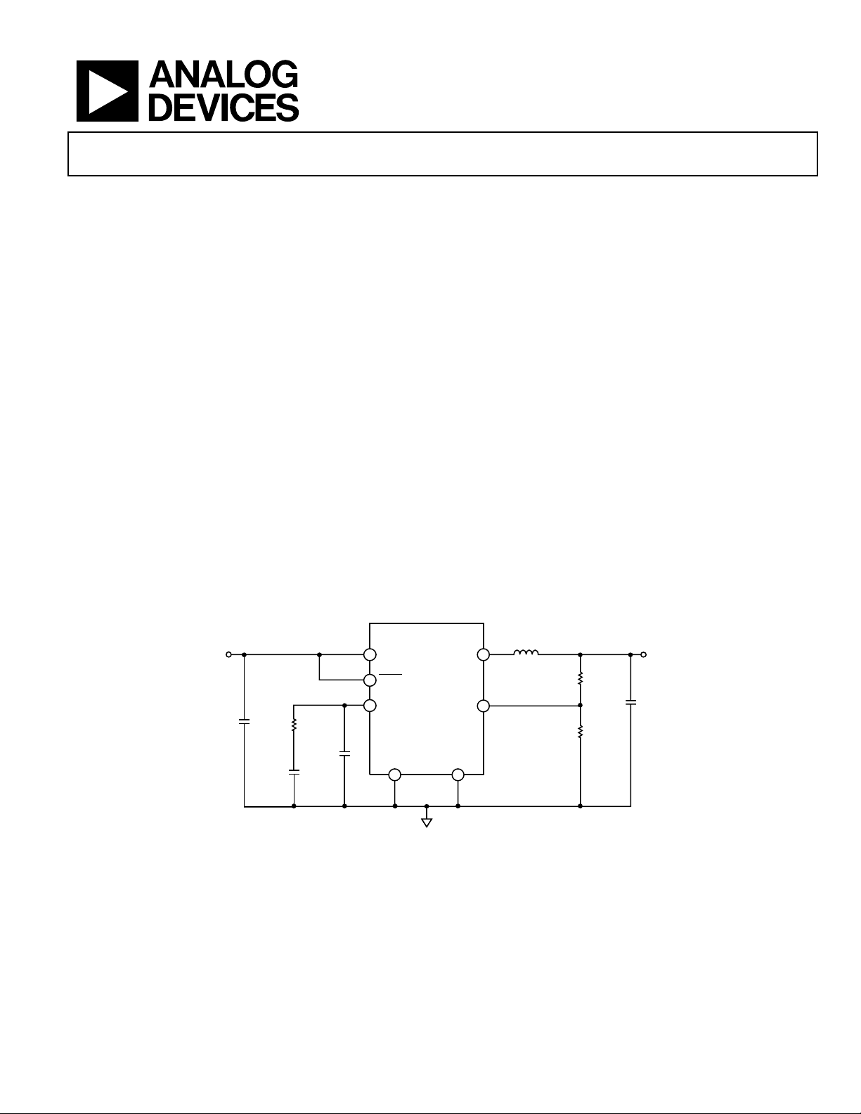
TYPICAL APPLICATION CIRCUIT
V
IN
10µF
3.3V
10kΩ
270pF
27pF
ADP3051
4
IN
SHDN
7
6
COMP FB
PGND GND
28
Figure 1.
SW
10µH
3
12.5kΩ
5
10kΩ
V
1.8V
OUT
10µF
04768-0-001
Rev. 0
Information furnished by Analog Devices is believed to be accurate and reliable.
However, no responsibility is assumed by Analog Devices for its use, nor for any
infringements of patents or other rights of third parties that may result from its use.
Specifications subject to change without notice. No license is granted by implication
or otherwise under any patent or patent rights of Analog Devices. Trademarks and
registered trademarks are the property of their respective owners.
One Technology Way, P.O. Box 9106, Norwood, MA 02062-9106, U.S.A.
Tel: 781.329.4700
Fax: 781.326.8703 © 2004 Analog Devices, Inc. All rights reserved.
www.analog.com
Page 2

ADP3051
TABLE OF CONTENTS
Specifications..................................................................................... 3
Undervoltage L ockout (UVLO) ............................................... 10
Absolute Maximum Ratings............................................................ 4
ESD Caution.................................................................................. 4
Pin Configuration and Function Descriptions............................. 5
Typical Performance Characteristics............................................. 6
Theory of Operation ........................................................................ 9
PWM Control Mode.................................................................... 9
Tri-Mode Operation..................................................................... 9
100% Duty Cycle Operation ..................................................... 10
Shutdown..................................................................................... 10
REVISION HISTORY
6/04—Revision 0: Initial Version
Short-Circuit Protection and Recovery................................... 10
Applications..................................................................................... 11
Recommended Components .................................................... 11
Design Procedure....................................................................... 11
Output Capacitor Selection....................................................... 12
Circuit Board Layout Considerations...................................... 13
Outline Dimensions....................................................................... 15
Ordering Guide .......................................................................... 15
Rev. 0 | Page 2 of 16
Page 3
ADP3051
SPECIFICATIONS
VIN = 3.6 V @ TA = –40°C to +85°C, unless otherwise noted.
Table 1.
Parameter Conditions Min Typ Max Unit
SUPPLY
Input Voltage Range 2.7 5.5 V
Quiescent Supply Current VFB = 1.0 V 180 300 µA
Shutdown Supply Current
PWM COMPARATOR
Minimum Duty Ratio 0 %
Maximum Duty Ratio 100 %
OSCILLATOR
Oscillator Frequency V
Foldback Frequency V
OUTPUT STAGE
On Resistance, N Channel ISW = 150 mA 150 mΩ
Switch Leakage Current, N Channel VIN = 5.0 V, VSW = 0 V 1 µA
On Resistance, P Channel FB = GND 190 mΩ
Switch Leakage Current, P Channel VSW = 5.0 V 1 µA
Current Limit Threshold 680 1000 1320 mA
ERROR AMPLIFIER
Feedback Input Bias Current 5 nA
Current Sense Gain 2.9 Ω
Transconductance 0.32 mS
Maximum Sink Current 33 µA
Maximum Source Current 33 µA
UNDERVOLTAGE LOCKOUT
Undervoltage Lockout Threshold VIN rising 1.9 2.6 V
Undervoltage Lockout Hysteresis 55 mV
SHDN INPUT THRESHOLD VOLTAGES
Input High Threshold Voltage Referenced to IN −0.5 V
Input Low Threshold Voltage 0.4 V
1
All limits at temperature extremes are guaranteed via correlation using standard statistical quality control (SQC).
1
SHDN = 0 V
≥ 1.5 V, V
COMP
< 0.3 V 200 kHz
OUT
= 0.7 V 410 550 690 kHz
OUT
TA = 25°C 783 800 821 mV Feedback Regulation Voltage
770 830 mV
10 25 µA
Rev. 0 | Page 3 of 16
Page 4
ADP3051
ABSOLUTE MAXIMUM RATINGS
Table 2.
Parameter Rating
IN, SHDN, COMP, SW, FB to GND
SW to IN –6 V to +0.3 V
PGND to GND –0.3 V to +0.3 V
Operating Ambient Temperature –40°C to +85°C
Operating Junction Temperature –40°C to +125°C
Storage Temperature –65°C to +150°C
θJA, 2-Layer (SEMI standard board) 159°C/W
θJA, 4-Layer (JEDEC standard board) 116°C/W
Lead Temperature Range
Soldering (10 sec) 300°C
Vapor Phase (60 sec) 215°C
Infrared (15 sec) 220°C
–0.3 V to +6 V
ESD CAUTION
ESD (electrostatic discharge) sensitive device. Electrostatic charges as high as 4000 V readily accumulate on
the human body and test equipment and can discharge without detection. Although this product features proprietary ESD protection circuitry, permanent damage may occur on devices subjected to high energy electrostatic discharges. Therefore, proper ESD precautions are recommended to avoid performance degradation or
loss of functionality.
Stresses above those listed under Absolute Maximum Ratings
may cause permanent damage to the device. This is a stress rating only; functional operation of the device at these or any
other conditions above those indicated in the operational sections of this specification is not implied. Exposure to absolute
maximum rating conditions for extended periods may affect
device reliability. Absolute maximum ratings apply individually
only, not in combination. Unless otherwise specified, all other
voltages are referenced to GND.
Rev. 0 | Page 4 of 16
Page 5
ADP3051
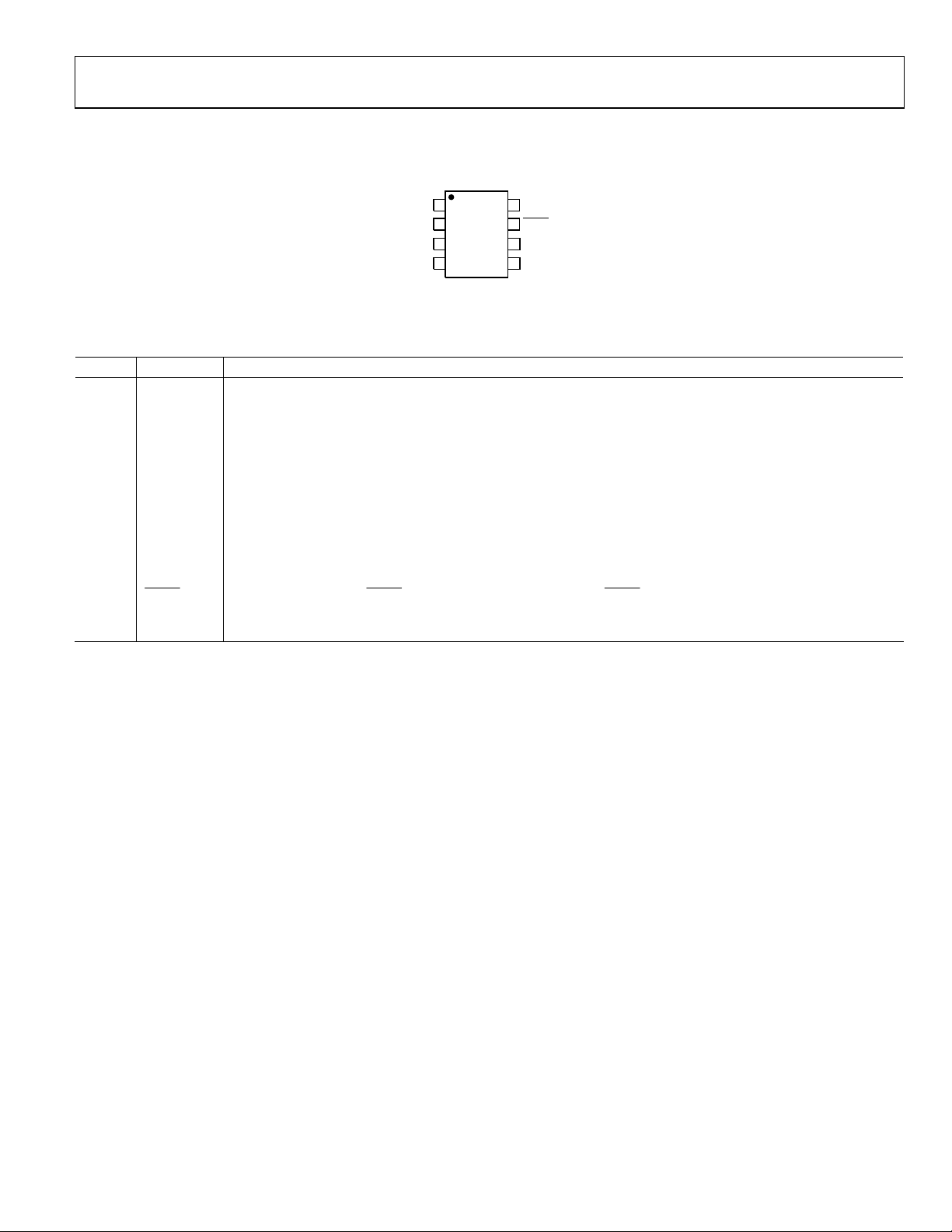
PIN CONFIGURATION AND FUNCTION DESCRIPTIONS
1
NC
2
PGND
3
SW
4
IN
Figure 2. 8-Lead MSOP Pin Configuration
Table 3. Pin Function Descriptions
Pin No. Mnemonic Description
1 NC No Connect. Not internally connected.
2 PGND
Power Ground. Connect PGND to GND at a single point. Use separate power ground and quiet ground planes for
the power and sensitive analog circuitry, respectively. See the Circuit Board Layout Considerations section.
3 SW
Switching Output. SW connects to the drain of the internal power switch and synchronous rectifier. Connect the
output inductor between SW and the load.
4 IN
Power Source Input. IN is the source of the high side P-channel MOSFET switch, and supplies the internal power to
the ADP3051. Bypass IN to GND with a 0.1 µF or greater ceramic capacitor, placed as close as possible to IN.
5 FB
Feedback Voltage Sense Input. FB senses the output voltage. To set the output voltage, connect a resistive voltage divider from the output voltage to FB. The feedback threshold is 0.8 V. See the Setting the Output Voltage
section.
6 COMP
Feedback Loop Compensation Node. COMP is the output of the internal transconductance error amplifier. Place a
series RC network from COMP to GND to compensate the regulator. See the Compensation Design section.
7
SHDN Shutdown Input. Drive SHDN low to turn off the ADP3051; drive SHDN to within 0.5 V of VIN to turn on the
ADP3051. See the Shutdown section.
8 GND Ground.
ADP3051
TOP VIEW
(Not to Scale)
8
7
6
5
GND
SHDN
COMP
FB
04768-0-021
Rev. 0 | Page 5 of 16
Page 6

ADP3051
TYPICAL PERFORMANCE CHARACTERISTICS
VIN = 3.6V, V
100
90
80
70
EFFICIENCY (%)
60
50
40
1 10010 1000
100
90
= 3.3V, circuit of Figure 20, component values of Table 4, TA = 25°C, unless otherwise specified.
OUT
VIN = 3.6V
V
= 5.5V
IN
V
= 3.3V
OUT
L = 22µH
I
(mA)
LOAD
Figure 3. Output Efficiency vs. Load Current, V
= 2.7V
V
IN
OUT
= 3.3 V
04768-0-002
0.5
0.4
0.3
0.2
0.1
0
–0.1
–0.2
OUTPUT ACCURACY (%)
–0.3
–0.4
–0.5
0 100 200 300 400 500
(mA)
I
LOAD
Figure 6. Output Voltage Error vs. Load Current
600
580
V
V
OUT
= 3.6V
IN
= 2.5V
04768-0-005
80
VIN = 3.6V
70
EFFICIENCY (%)
60
50
40
1 10010 1000
V
= 5.5V
IN
I
LOAD
(mA)
Figure 4. Output Efficiency vs. Load Current, V
100
= 3.6V
90
VIN = 2.5V
80
70
EFFICIENCY (%)
60
50
40
1 10010 1000
V
IN
V
= 5.5V
IN
I
LOAD
(mA)
Figure 5. Output Efficiency vs. Load Current, V
= 2.5V
V
OUT
L = 22µH
C
= 22µF
OUT
= 2.5 V
OUT
V
= 1.2V
OUT
L = 10µH
C
= 22µF
OUT
= 1.2 V
OUT
04768-0-003
04768-0-004
560
= 5.5V
V
IN
540
520
FREQUENCY (kHz)
500
480
–40 –15 10 35 60 85
TEMPERATURE (°C)
V
= 3.6V
IN
VIN = 2.7V
V
OUT
I
LOAD
Figure 7. Oscillator Frequency vs. Temperature
600
550
500
450
400
350
300
250
200
150
OSCILLATOR FREQUENCY (kHz)
100
50
0
0 100 200 300 400 500
(mA)
I
LOAD
Figure 8. Oscillator Frequency vs. Load Current, V
= 3.6 V, V
IN
= 1.2V
= 500mA
OUT
= 1.2 V
04768-0-006
04768-0-007
Rev. 0 | Page 6 of 16
Page 7

ADP3051
CH1 = VIN, CH2 = SW, CH3 = V
= 3.6V, V
V
IN
OUT
= 1.2V, I
LOAD
OUT
= 500mA
, CH4 = IL (1A/DIV)
Figure 9. Start -Up Behav ior
CH2 = IL (100mA/DIV), CH4 = SW
= 3.6V, V
V
IN
= 2.5V, L = 22µH, I
OUT
OUT
= 50mA
Figure 10. Light Load Switching Waveforms
CH2 = IL (500mA/DIV), CH4 = SW
= 3.6V, V
V
IN
= 2.5V, L = 22µH, I
OUT
OUT
= 500mA
Figure 11. Heavy Load Switching Waveforms
04768-0-008
04768-0-009
04768-0-010
CH1 = COMP, CH3 = V
= 3.6V, V
V
IN
OUT
= 2.5V, C
, CH4 = I
OUT
= 22µF, CC = 150pF, RC = 100kΩ
OUT
(50mA TO 490mA)
LOAD
Figure 12. Load Transient Response
CH1 = VIN, CH2 = V
VIN = 3V TO 4V, V
OUT
OUT
= 2.5V, I
LOAD
= 500mA
Figure 13. Line Transient Response
210
200
190
180
)
170
Ω
(m
160
DSON
150
R
140
130
120
110
2.7 3.1 3.5 3.9 4.3 4.7 5.1 5.5
PMOS
NMOS
SUPPLY VOLTAGE (V)
V
I
OUT
OUT
Figure 14. Switch On Resistance vs. Input Voltage
= 2.5V
= 500mA
04768-0-011
04768-0-012
04768-0-013
Rev. 0 | Page 7 of 16
Page 8

ADP3051
240
220
200
A)
µ
180
160
140
120
SUPPLY CURRENT (
100
80
60
2.7 3.1 3.5 3.9 4.3 4.7 5.1 5.5
Figure 15. Quiescent Current vs. Input Voltage
TA = +85°C
TA = +25°C
TA = –40°C
SUPPLY VOLTAGE (V)
V
I
LOAD
OUT
= 1.2V
= 0mA
04768-0-014
1200
1150
1100
1050
1000
950
900
CURRENT LIMIT (A)
850
800
750
700
–40 –15 10 35 60 85
V
= 5.5V
IN
= 3.6V
V
IN
VIN = 2.7V
TEMPERATURE (°C)
V
OUT
Figure 16. Current Limit vs. Input Voltage, V
OUT
= 1.2V
= 1.2 V
04768-0-015
Rev. 0 | Page 8 of 16
Page 9

ADP3051
C
THEORY OF OPERATION
The ADP3051 is a monolithic current mode buck converter
with an integrated high-side switch and low-side synchronous
rectifier. It operates with input voltages between 2.7 V and 5.5 V,
regulates an output voltage down to 0.8 V, and supplies more
than 500 mA of load current. The ADP3051 features patented
Tri-Mode technology to operate in fixed frequency PWM mode
at medium to heavy loads. This improves light-load efficiency
by smoothly transitioning into a variable frequency PWM
mode, and into a single-pulse, current-limited variable
frequency mode at very light loads.
PWM CONTROL MODE
At moderate to high output currents, the ADP3051 operates
in a fixed frequency, peak current control mode to regulate the
output voltage. At the beginning of each cycle, the P-channel
output switch turns on and remains on until the inductor current exceeds the threshold set by the voltage at COMP. When
the P-channel switch turns off, the N-channel synchronous
rectifier turns on for the remainder of the cycle, after which the
cycle repeats.
In current mode, two cascaded control loops combine to regulate the output voltage. The outer voltage control loop senses the
voltage at FB and compares it to the internal 0.8 V reference.
The internal transconductance amplifier forces a current at
COMP proportional to the voltage difference between the reference and FB. By selecting the components between COMP and
GND, the frequency characteristics of the control system give a
stable regulation system.
The inner peak-current control loop monitors the current flowing through the P-channel MOSFET and converts that to a
voltage. This voltage is internally compared to the voltage at
7
SHDN
0.4V
FREQUENCY
FOLDBACK
COMPARATOR
CONTROL
LOGIC
UVLO
COMP, which sets inductor peak current. The error amplifier,
and thus the output voltage, controls the inductor peak current
to regulate the output voltage. An internally generated slope
compensation circuit ensures that the inner current control
loop maintains stable operation over the entire input and output
voltage range.
TRI-MODE OPERATION
The ADP3051 features patented Tri-Mode technology which
allows fixed-frequency, current mode, PWM operation at
medium and heavy loads; smoothly transitions to variable
frequency PWM operation to improve light-load efficiency; and
operates in a single-pulse, current-limited variable frequency
mode at very light loads. These three modes work together to
provide high efficiency over a wide range of load current conditions without the frequency jitter, increased output voltage
ripple, and audible noise generation exhibited by other lightload control schemes.
The ADP3051’s internal oscillator is a key component of its
Tri-Mode operation. Under medium-heavy load conditions, the
oscillator operates at a constant 550 kHz. Under light-load
conditions, the oscillator frequency is decreased to minimize
switching losses, thus improving light-load efficiency. At very
light loads, the oscillator is disabled and the ADP3051 switches
only as required to supply the load current for good light-load
efficiency.
In addition to Tri-Mode operation, the ADP3051 operates in the
200 kHz frequency foldback mode when the voltage at FB is
below 0.3 V for enhanced control of the inductor current under
short-circuit and startup conditions. See the Short-Circuit Protection and Recovery section.
4
IN
VOLTAGE
CURRENT
SENSE
REFERENCE
OSCILLATOR
PWM
6
OMP
ERROR
AMPLIFIER
5
FB
0.8V
g
m
COMPARATOR
18
NC
Figure 17. Simplified Block Diagram
Rev. 0 | Page 9 of 16
GND
SRQ
GATE
DRIVERS
ADP3051
3
2
SW
PGND
04768-0-016
Page 10

ADP3051
100% DUTY CYCLE OPERATION
The ADP3051 is capable of operating at 100% duty cycle, allowing it to regulate output voltages that are very close to the input
voltage. In 100% duty cycle operation, the P-channel switch
remains continuously on, and the dropout voltage is simply the
output current multiplied by the on resistance of the internal
switch and inductor, typically 200 mV at full loads (500 mA).
SHUTDOWN
The ADP3051 is enabled and disabled via its
easily interfaces to open-drain and three-state logic
SHDN
GPIOs. To enable the ADP3051, drive
SHDN
the voltage at IN; to disable the ADP3051, drive
0.4 V. The circuit of Figure 18 shows a simple means of driving
to the proper high and low input states in cases where no
SHDN
open-drain or three-state GPIO is available.
IN
100kΩ
SHDN
SHDN
CONTROL
ADP3051
Figure 18. Shutdown Control Circuit
input.
SHDN
to within 0.5 V of
below
SHDN
04768-0-017
UNDERVOLTAGE LOCKOUT (UVLO)
The ADP3051 includes an internal undervoltage lockout
(UVLO) circuit that turns off the converter if the input
voltage drops below the 2.2 V UVLO threshold. This prevents
uncontrolled behavior if the input voltage drops below the 2.7 V
minimum allowable voltage range. The UVLO circuit includes
55mV of hysteresis to prevent oscillation at the UVLO
threshold.
SHORT-CIRCUIT PROTECTION AND RECOVERY
When starting up or when the output is short circuited, the low
voltage drop across the synchronous rectifier may allow the
inductor current to run away because it rises more during the
on time than it falls during the off time. To protect against this,
the ADP3051 automatically initiates a frequency foldback
operation when the voltage at FB drops below 0.3 V, allowing
the ADP3051 to maintain control of the inductor current under
these conditions.
When operating at higher input voltages (for example, from a
5 V bus), the ADP3051 may exhibit output voltage overshoot
upon startup or after release of an overload condition (see
Figure 9). In such cases, the ADP3051’s limited COMP slew rate
can slow its recovery as the output approaches regulation,
allowing the output voltage to overshoot. If overshoot cannot be
tolerated in an application, the COMP voltage can be limited by
placing a Zener diode from COMP to GND, as shown in Figure 19.
6
COMP
CMPZ4683-ADC
ADP3051
04768-0-023
Figure 19. COMP Zener Clamp to Prevent
Short-Circuit Recovery Output Voltage Overshoot
Rev. 0 | Page 10 of 16
Page 11

ADP3051
V
APPLICATIONS
Where
V
RECOMMENDED COMPONENTS
External component selection for the application circuit shown
in Figure 20 depends on the load current requirements. Certain
tradeoffs between different performance parameters can also be
made. Recommended external component values are given in
Tabl e 4.
ADP3051
V
IN
C
IN
43
7
8
IN
SHDN
GND
SW
FB
COMP
PGND
2
Figure 20. Typical Application Circuit
L
R
A
5
6
C2
R
B
R
C
C1
V
OUT
C
OUT
04768-0-018
DESIGN PROCEDURE
For applications where specific performance is required, component combinations other than those listed in Table 4 may be
more appropriate. A design procedure for selecting the components is provided in the following sections.
Setting the Output Voltage
The regulated output voltage of the ADP3051 is set by selecting
the resistive voltage divider formed by R
Figure 21). The voltage divider drops the output voltage to the
voltage at FB by the equation
and RB (see
A
regulation threshold.
I
, which is calculated by
DIV
Using higher divider current increases accuracy due to the 5 nA
FB input bias current. With
degraded by 0.0625%.
For a given
by the equation
is the output voltage and VFB is the 0.8 V feedback
OUT
R
controls the voltage divider current,
B
I =
FB
DIV
R
B
R
= 100 kΩ, the accuracy is
B
R
, choose the value of RA to set the output voltage
B
A
V
⎝
V
⎛
RR
⎜
B
OUT
FB
−= 1
⎞
⎟
⎠
ADP3051
FB
5
REF
g
m
ERROR
AMPLIFIER
6
COMP
R
C1
C
C2
R
R
Figure 21. Typical Compensation Network
V
OUT
A
B
04768-0-019
R
⎞
⎛
VV 1
FB
OUT
A
+=
⎟
⎜
R
B
⎠
⎝
Table 4. Recommended External Components for Popular Input/Output Voltage Conditions
(Based on I
VIN V
= 500 mA Max and a 60 kHz Crossover Frequency)
LOAD
L (µH) C
OUT
(µF) CIN (µF) RA (kΩ) RB (kΩ) RC (kΩ) C1 (pF) C2 (pF)
OUT
2.5 1.0 6.8 10 10 2.5 10 4.7 470 47
1.8 6.8 10 10 12.5 10 10 270 27
3.6 1.0 6.8 10 10 2.5 10 4.7 470 47
1.8 8.2 10 10 12.5 10 10 270 27
2.5 8.2 10 10 21.3 10 15 180 18
5.0 1.0 8.2 10 10 2.5 10 5.7 470 47
1.8 10 10 10 12.5 10 10 270 27
2.5 10 10 10 21.3 10 15 180 18
3.3 12 10 10 31.3 10 18 150 15
Rev. 0 | Page 11 of 16
Page 12

ADP3051
V
I
∆
V
×××
Inductor Selection
The ADP3051’s high switching frequency allows the use of a
physically small inductor. The inductor ripple current is determined by
()
VVV
−×
IN
OUT
I
=∆
L
Where ∆
IN
I
is the peak-to-peak inductor ripple current and fSW is
L
the switching frequency. As a guideline, the inductor peak-topeak current ripple is typically set to be one-third the maximum
dc load current. Using this guideline and solving for
L
OUT
IN
SW
Simplifying for the known constants
OUT
×=
μH5
L
It is important to ensure that the inductor is capable of handling
the maximum peak inductor current, I
II
LPK
()
MAXLOAD
Finally, the ADP3051’s internal slope compensation is designed
to ensure stability of the inner current mode control loop when
the inductor is chosen so that the down-slope of the inductor
current is less than 320 mA/µs
V
L ≥
OUT
μs/mA320
OUTPUT CAPACITOR SELECTION
The output capacitor should be chosen to meet output voltage
ripple requirements for the application. Output voltage ripple is
a function of the inductor ripple current and the impedance of
the output capacitor at the switching frequency. The magnitude
of the capacitive impedance is
COUT
OUT
LfV
××
SW
()
−××=3
VVV
IN
OUT
()
MAXLOAD
−×
VVV
IN
OUT
MAXLOAD
I
∆
⎛
⎞
L
⎜
⎟
2
⎝
⎠
)(
, determined by
LPK
××
IfV
()
×
IV
IN
+=
1
OUT
fCX××π=2
SW
L,
Where V
ESR
COUT
is the peak-to-peak output ripple voltage and
RIPPLE
is the output capacitor ESR. For capacitors with relatively small capacitance and/or resistance, the capacitance
dominates the output voltage ripple. In this case, choose the
output capacitor by the capacitance using the equation
V
C
OUT
()
C
≥
OUT
8
SW
IN
SW
∆
×××≥22π
L
Vf
OUT
VLf
RIPPLE
Multilayer ceramic (MLC), tantalum, OS-CON, or similar low
ESR capacitors are recommended. Table 5 lists some vendors
that make suitable capacitors.
Table 5. Capacitor Suppliers
Manufacturer Capacitor Type Contact Info
AVX Tantalum www.avxcorp.com
Murata MLCC www.murata.com
Sanyo OS-CON www.sanyovideo.com
Taiyo-Yuden MLCC www.t-yuden.com
Input Capacitor Selection
The input capacitor reduces input voltage ripple caused by
switch currents. Select an input capacitor capable of withstanding the rms input current
()
VVV
−
IN
OUT
V
IN
Where I
II
≥
is the rms ripple rating of the input capacitor. As
CIN(RMS)
OUT
MAXLOADRMSCIN
)()(
with the output capacitor, a low ESR capacitor is recommended
to help to minimize input voltage ripple.
Compensation Design
The ADP3051’s external compensation network allows designers to easily optimize the part’s performance for a particular
application with just a series RC network (R
and C1 of
C
Figure 21) from COMP to GND typically required to
compensate the regulator.
The dc loop gain is given by the equation
For capacitors with relatively large capacitance or high
equivalent series resistance (ESR), e.g., tantalum or electrolytic
A
FB
=
VDC
OUT
RRG
LOADOEAEA
RV
×
CS
capacitors, the ESR dominates the impedance at the switching
frequency; therefore, the output ripple voltage is mainly a function of ESR. In this case, the output capacitor should be chosen
based on the ESR by the equation
ESR∆≤
COUT
RIPPLE
I
L
where:
is the feedback voltage regulation threshold, 0.8 V.
V
FB
is the error amplifier transconductance, 320 µs.
G
EA
is the error amplifier output impedance (10 MΩ).
R
OEA
is the 2.9 Ω current sense gain.
R
CS
R
is the equivalent output resistance, equal to the output
LOAD
voltage divided by the load current.
Rev. 0 | Page 12 of 16
Page 13

ADP3051
The system has three poles and a zero that dominate its frequency response. The first compensation pole is given by
f
=
1
PC
1
OEA
12
CR
××π
The output pole is given by
POUT
1
LOAD
CRf××π=2
OUT
If used, the optional second compensation pole is given by
f
2
PC
1
=
22
CR
××π
C
Finally, the zero can be calculated as
f
ZC
1
=
12
CR
××π
C
Note that the dc loop gain is the inverse of the output load
current, while the output pole, f
, is proportional to the load
POUT
current. Thus, the crossover frequency, which is proportional to
the product of the dc loop gain and the output pole frequency,
remains the same.
To choose the compensation components, first choose the
regulator loop crossover frequency (the frequency where the
loop gain drops to 1 V/V or 0 dB). To determine the desired
crossover frequency, chose it for about one-tenth of the switching frequency or 60 kHz. The required compensation resistor,
, can be determined from the equation
R
C
CRVf
××××π=2
R
Where f
C
C
C
REF
is the crossover frequency. To make sure the phase
OUT
CS
OUT
GV
×
EA
margin is suitable, choose the first compensation capacitor to
set the zero frequency to one-fourth the crossover frequency, or
1
4
RfC××π=2
CC
An optional second compensation capacitor reduces the high
frequency gain to reduce the high frequency noise. If used,
choose the second compensation capacitor to set the second
compensation pole to the switching frequency, or
=
2
1
2
RfC××π
CSW
CIRCUIT BOARD LAYOUT CONSIDERATIONS
A good circuit board layout aids in extracting the most
performance from the ADP3051. Poor circuit layout degrades
the output ripple and the electromagnetic interference (EMI) or
electromagnetic compatibility (EMC) performance.
The evaluation board layout of Figure 24 is optimized for the
ADP3051. Use this layout for best performance. If this layout
needs changing, use the following guidelines:
Use separate analog and power ground planes. Connect the
1.
sensitive analog circuitry (such as compensation and voltage divider components) to analog ground; connect the
power components (such as input and output bypass
capacitors) to power ground. Connect the two ground
planes together near the load to reduce the effects of
voltage dropped on circuit board traces.
Locate C
2.
rate input bypass capacitors for the analog and power
grounds indicated in Guideline 1.
3.
Route the high current path from C
and PGND pins as short as possible.
4.
Route the high current path from C
as short as possible.
5.
Keep high current traces as short and as wide as possible.
6.
Place the feedback resistors as close as possible to the FB
pin to prevent noise pickup.
7.
Place the compensation components as close as possible to
the COMP pin.
Avoid routing high impedance traces, such as FB and
8.
COMP, near the high current traces and components or
near the switch node (SW).
If high impedance traces are routed near high current
9.
and/or the SW node, place a ground plane shield between
the traces.
as close to the IN pin as possible, and use sepa-
IN
, through L, to the SW
IN
through L and C
IN
OUT
Rev. 0 | Page 13 of 16
Page 14

ADP3051
Figure 22. Sample Application Circuit Board Layout (Silkscreen Layer)
Figure 23. Sample Application Circuit Board Layout ( Top Layer)
04768-0-024
04768-0-026
Figure 24. Sample Application Circuit Board Layout (Bottom Layer)
04768-0-025
Rev. 0 | Page 14 of 16
Page 15

ADP3051
OUTLINE DIMENSIONS
3.00
BSC
85
3.00
BSC
PIN 1
0.65 BSC
0.15
0.00
0.38
0.22
COPLANARITY
0.10
COMPLIANT TO JEDEC STANDARDS MO-187AA
BSC
4
SEATING
PLANE
4.90
1.10 MAX
0.23
0.08
8°
0°
0.80
0.60
0.40
Figure 25. 8-Lead Mini Small Outline Package [MSOP]
(RM-8)
Dimensions shown in millimeters
ORDERING GUIDE
Model Temperature Range Package Description Package Outline Branding
ADP3051ARMZ-REEL7
1
Z = Pb-free part.
1
–40°C to +85°C 8-Lead Mini Small Outline Package [MSOP] RM-8 P3A
Rev. 0 | Page 15 of 16
Page 16

ADP3051
NOTES
© 2004 Analog Devices, Inc. All rights reserved. Trademarks and registered trademarks are the property of their respective owners.
D04768–0–6/04(0)
Rev. 0 | Page 16 of 16
 Loading...