

Page 1
Omnidirectional Microphone with
Data Sheet
FEATURES
Tiny 3.35 mm × 2.50 mm × 0.88 mm surface-mount package
High SNR of 62 dBA
High sensitivity of −38 dBV
Flat frequency response from 100 Hz to 15 kHz
Low current consumption: <250 μA
Single-ended analog output
High PSRR of 70 dB
Compatible with Sn/Pb and Pb-free solder processes
RoHS/WEEE compliant
APPLICATIONS
Smartphones and feature phones
Teleconferencing systems
Digital video cameras
Bluetooth headsets
Video phones
Tab le ts
Bottom Port and Analog Output
ADMP404
GENERAL DESCRIPTION
The ADMP404 is a high quality, high performance, low power,
analog output bottom-ported omnidirectional MEMS microphone.
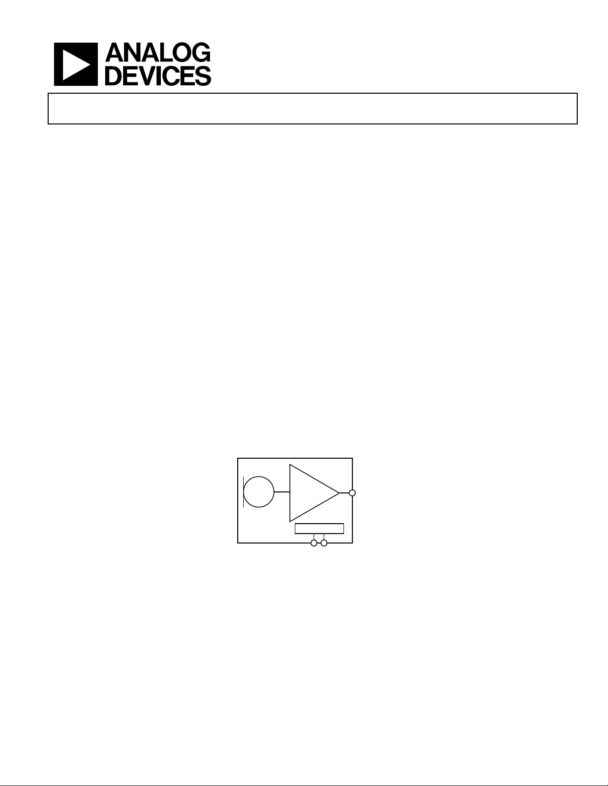
The ADMP404 consists of a MEMS microphone element, an
impedance converter, and an output amplifier. The ADMP404
sensitivity specification makes it an excellent choice for both
near field and far field applications. The ADMP404 has a high
signal-to-noise ratio (SNR) and flat, wideband frequency response,
resulting in natural sound with high intelligibility. Its low current
consumption enables long battery life for portable applications.
A built-in particle filter provides high reliability. The ADMP404
complies with the TIA-920 Telecommunications Telephone
Terminal Equipment Transmission Requirements for Wideband
Digital Wireline Telephones standard.
The ADMP404 is available in an ultraminiature 3.35 mm ×
2.50 mm × 0.88 mm surface-mount package. It is reflow solder
compatible with no sensitivity degradation. The ADMP404 is
halide free.
FUNCTIONAL BLOCK DIAGRAM
ADMP404
Rev. B
Information furnished by Analog Devices is believed to be accurate and reliable. However, no
responsibility is assumed by Anal og Devices for its use, nor for any infringements of patents or ot her
rights of third parties that may result from its use. Specifications subject to change without notice. No
license is granted by implication or otherwise under any patent or patent rights of Analog Devices.
Trademarks and registered trademarks are the property of their respective owners.
OUTPUT
AMPLIF IER
POWER
VDD
Figure 1.
OUTPUT
GND
One Technology Way, P.O. Box 9106, Norwood, MA 02062-9106, U.S.A.
Tel: 781.329.4700 www.analog.com
Fax: 781.461.3113 ©2010–2011 Analog Devices, Inc. All rights reserved.
08616-001
Page 2

ADMP404 Data Sheet
TABLE OF CONTENTS
Features.............................................................................................. 1
Applications....................................................................................... 1
General Description ......................................................................... 1
Functional Block Diagram .............................................................. 1
Revision History ............................................................................... 2
Specifications..................................................................................... 3
Absolute Maximum Ratings............................................................ 4
ESD Caution.................................................................................. 4
Pin Configuration and Function Descriptions............................. 5
Typical Performance Characteristics ............................................. 6
Applications Information ................................................................ 7
REVISION HISTORY
8/11—Rev. A to Rev. B
Changes to Figure 1.......................................................................... 1
Changes to Supply Voltage Parameter, Table 1............................. 3
Changes to Table 3............................................................................ 4
Added Connecting to Analog Devices, Inc., Audio Codecs
Section and Supporting Documents Section ................................ 7
Changes to Pick and Place Equipment Section
(20 kg to 10 kg).................................................................................. 9
Added LGA_CAV Tape and Reel Outline Dimensions,
Figure 12 ..........................................................................................11
Connecting to Analog Devices, Inc., Audio Codecs ................7
Supporting Documents ................................................................7
PCB Land Pattern Layout.................................................................8
Handling Instructions.......................................................................9
Pick and Place Equipment............................................................9
Reflow Solder .................................................................................9
Board Wash ....................................................................................9
Reliability Specifications................................................................ 10
Outline Dimensions....................................................................... 11
Ordering Guide .......................................................................... 11
12/10—Rev. 0 to Rev. A
Changes to Applications Section and General
Description Section...........................................................................1
Changes to Table 1.............................................................................3
Changes to Table 2.............................................................................4
7/10—Revision 0: Initial Version
Rev. B | Page 2 of 12
Page 3

Data Sheet ADMP404
SPECIFICATIONS
TA = 25°C, VDD = 1.8 V, unless otherwise noted. All minimum and maximum specifications are guaranteed. Typical specifications are not
guaranteed.
Table 1.
Parameter Symbol Test Conditions/Comments Min Typ Max Unit
PERFORMANCE
Directionality Omni
Sensitivity 1 kHz, 94 dB SPL −41 −38 −35 dBV
Signal-to-Noise Ratio SNR 62 dBA
Equivalent Input Noise EIN 32 dBA SPL
Dynamic Range Derived from EIN and maximum acoustic input 88 dB
Frequency Response1 Low frequency −3 dB point 100 Hz
High frequency −3 dB point 15 kHz
Deviation limits from flat response within pass band −3/+2 dB
Total Harmonic Distortion THD 105 dB SPL 3 %
Power Supply Rejection Ratio PSRR 217 Hz, 100 mV p-p square wave superimposed on VDD = 1.8 V 70 dB
Maximum Acoustic Input Peak 120 dB SPL
POWER SUPPLY
Supply Voltage VDD 1.5 3.3 V
Supply Current IS 250 μA
OUTPUT CHARACTERISTICS
Output Impedance Z
Output DC Offset 0.8 V
Output Current Limit 90 μA
1
See and . Figure 4 Figure 6
200 Ω
OUT
Rev. B | Page 3 of 12
Page 4
ADMP404 Data Sheet
ABSOLUTE MAXIMUM RATINGS
Table 2.
Parameter Rating
Supply Voltage −0.3 V to +3.6 V
Sound Pressure Level (SPL) 160 dB
Mechanical Shock 10,000 g
Vibration
Per MIL-STD-883 Method 2007,
Test Condition B
Temperature Range −40°C to +70°C
T
P
T
L
T
SMAX
RAMP-UP
Stresses above those listed under Absolute Maximum Ratings
may cause permanent damage to the device. This is a stress
rating only; functional operation of the device at these or any
other conditions above those indicated in the operational
section of this specification is not implied. Exposure to absolute
maximum rating conditions for extended periods may affect
device reliability.
ESD CAUTION
t
P
CRITICAL Z ONE
t
L
T
TO T
L
P
T
SMIN
TEMPERATURE
t
S
PREHEAT
t
25°C
TO PEAK
TIME
RAMP-DOWN
08616-002
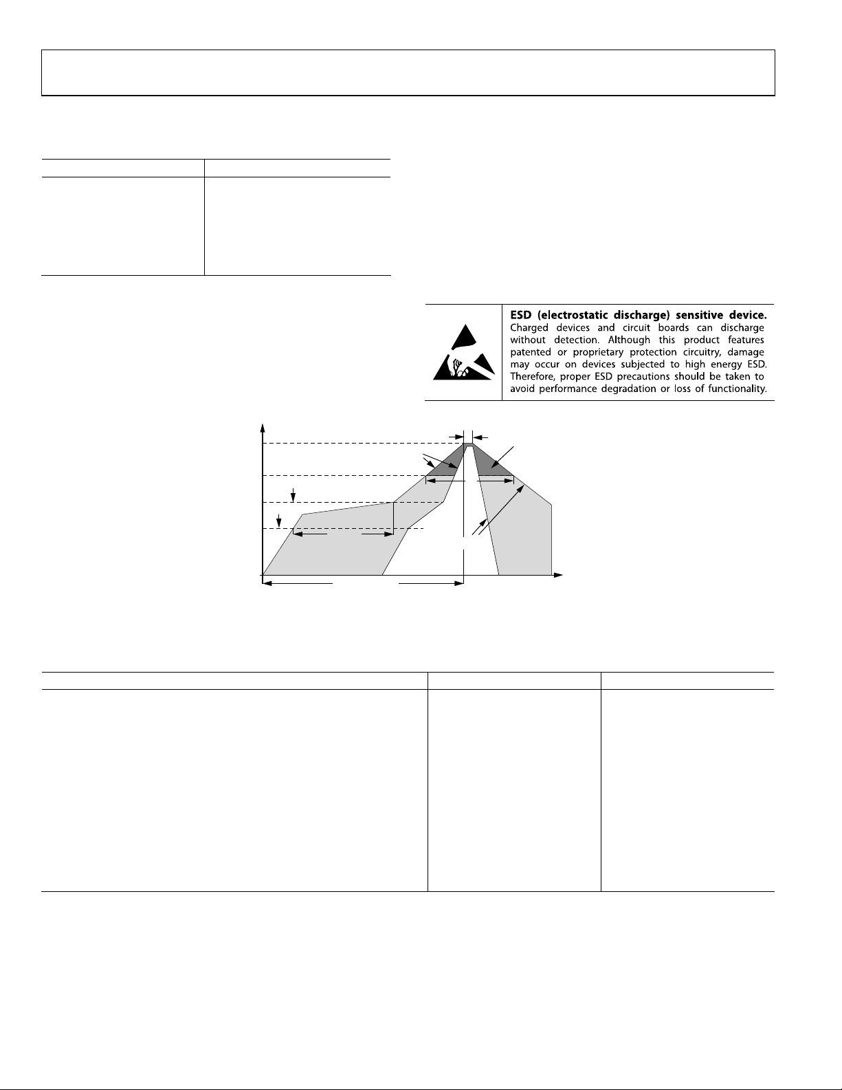
Figure 2. Recommended Soldering Profile Limits
Table 3. Recommended Soldering Profile Limits
Profile Feature Sn/Pb Pb-Free
Average Ramp Rate (TL to TP) 1.25°C/sec maximum 1.25°C/sec maximum
Preheat
Minimum Temperature (T
Maximum Temperature (T
Time (T
Ramp-Up Rate (T
SMIN
to T
), tS 60 sec to 75 sec 60 sec to 75 sec
SMAX
to TL) 1.25°C/sec 1.25°C/sec
SMAX
) 100°C 150°C
SMIN
) 150°C 200°C
SMAX
Time Maintained Above Liquidous (tL) 45 sec to 75 sec ~50 sec
Liquidous Temperature (TL) 183°C 217°C
Peak Temperature (TP) 215°C + 3°C/−3°C 245°C + 0°C/−5°C
Time Within 5°C of Actual Peak Temperature (tP) 20 sec to 30 sec 20 sec to 30 sec
Ramp-Down Rate 3°C/sec maximum 3°C/sec maximum
Time 25°C (t
) to Peak Temperature 5 minute maximum 5 minute maximum
25°C
Rev. B | Page 4 of 12
Page 5

Data Sheet ADMP404
PIN CONFIGURATION AND FUNCTION DESCRIPTIONS
GND
2
ADMP404
TOP VIEW
(TERMINAL S IDE DOWN)
Not to Scal e
Figure 3. Pin Configuration
1
OUTPUT
3
V
DD
Table 4. Pin Function Descriptions
Pin No. Mnemonic Description
1 OUTPUT Analog Output Signal
2 GND Ground
3 VDD Power Supply
08616-003
Rev. B | Page 5 of 12
Page 6

ADMP404 Data Sheet
TYPICAL PERFORMANCE CHARACTERISTICS
10
8
6
4
2
0
–2
SENSITIVITY (dB)
–4
–6
–8
–10
100 10k
1k
FREQUENCY (Hz)
Figure 4. Frequency Response Mask
0
–10
08616-009
10
0
(dB)
–10
–20
100 10k
1k
FREQUENCY (Hz)
08616-010
Figure 6. Typical Frequency Response (Measured)
–20
–30
–40
PSRR (dB)
–50
–60
–70
–80
100 10k
1k
FREQUENCY (Hz)
Figure 5. Typical Power Supply Rejection Ratio vs. Frequency
08616-005
Rev. B | Page 6 of 12
Page 7

Data Sheet ADMP404
APPLICATIONS INFORMATION
CONNECTING TO ANALOG DEVICES, INC., AUDIO CODECS
The ADMP404 output can be connected to a dedicated codec
microphone input (see Figure 7) or to a high input impedance
gain stage (see Figure 8). A 0.1 μF ceramic capacitor placed close
to the ADMP404 supply pin is used for testing and is recommended to adequately decouple the microphone from noise on
the power supply. A dc-blocking capacitor is required at the
output of the microphone.
0.1µF
V
DD
ADMP404
OUTPUT
GND
2.2µF
MINIMUM
Figure 7. ADMP404 Connected to the Analog Devices ADAU1761 or
ADAU1361 Codec
MICBIAS
ADAU1761
OR
ADAU1361
LINN
LINP
CM
08616-020
GAIN = (R1 + R2)/R1
V
DD
ADMP404
OUTPUT
GND
0.1µF
MINIMUM
1µF
V
REF
10kΩ
R1 R2
V
REF
OP177
V
OUT
08616-021
Figure 8. ADMP404 Connected to the OP177 Op Amp
SUPPORTING DOCUMENTS
Evaluation Board User Guide
UG-142, EVAL-ADMP404Z-FLEX: Bottom-Ported Analog
Output MEMS Microphone Evaluation Board
Application Notes
AN-1003, Recommendations for Mounting and Connecting
Analog Devices, Inc., Bottom-Ported MEMS Microphones
AN-1068, Reflow Soldering of the MEMS Microphone
AN-1112, Microphone Specifications Explained
AN-1124, Recommendations for Sealing Analog Devices, Inc.,
Bottom-Port MEMS Microphones from Dust and Liquid
Ingress
Rev. B | Page 7 of 12
Page 8

ADMP404 Data Sheet
PCB LAND PATTERN LAYOUT
The recommended PCB land pattern for the ADMP404 should
be laid out to a 1:1 ratio to the solder pads on the microphone
package, as shown in Figure 9. Care should be taken to avoid
applying solder paste to the sound hole in the PCB. A suggested
0.68
solder paste stencil pattern layout is shown in Figure 10. The
diameter of the sound hole in the PCB should be larger than the
diameter of the sound port of the microphone. A minimum
diameter of 0.5 mm is recommended.
1.52
1.90
1.22
Ø1.55
Ø0.95
0.90
0.61
0.61
08616-007
Figure 9. PCB Land Pattern Layout
1.55/1.05 DI A.
2×0.8 × 0.6
1.22
0.2 × 45
TYP
Figure 10. Suggested Solder Paste Stencil Pattern Layout
0.225 CUT WIDTH (2×)
1.52mm
8616-008
Rev. B | Page 8 of 12
Page 9

Data Sheet ADMP404
HANDLING INSTRUCTIONS
PICK AND PLACE EQUIPMENT
The MEMS microphone can be handled using standard pickand-place and chip shooting equipment. Care should be taken
to avoid damage to the MEMS microphone structure as follows:
• Use a standard pickup tool to handle the microphone.
Because the microphone hole is on the bottom of the
package, the pickup tool can make contact with any part
of the lid surface.
• Use care during pick-and-place to ensure that no high
shock events above 10 kg are experienced because such
events may cause damage to the microphone.
• Do not pick up the microphone with a vacuum tool that
makes contact with the bottom side of the microphone.
Do not pull air out of or blow air into the microphone port.
• Do not use excessive force to place the microphone on
the PCB.
REFLOW SOLDER
For best results, the soldering profile should be in accordance
with the recommendations of the manufacturer of the solder
paste used to attach the MEMS microphone to the PCB. It is
recommended that the solder reflow profile not exceed the limit
conditions specified in Figure 2 and Ta ble 3.
BOARD WASH
When washing the PCB, ensure that water does not make
contact with the microphone port. Blow-off procedures and
ultrasonic cleaning must not be used.
Rev. B | Page 9 of 12
Page 10

ADMP404 Data Sheet
RELIABILITY SPECIFICATIONS
The microphone sensitivity after stress must deviate by no more than ±3 dB from the initial value.
Table 5.
Stress Test Description
Low Temperature Operating Life −40°C, 500 hours, powered
High Temperature Operating Life +125°C, 500 hours, powered
Temperature Humidity Bias (THB) +65°C/85% relative humidity (RH), 500 hours, powered
Temperature Cycle −40°C/+125°C, one cycle per hour, 100 cycles
High Temperature Storage +150°C, 500 hours
Low Temperature Storage −40°C, 500 hours
Component Charge Device Model (CDM) ESD All pins, 0.5 kV
Component Human Body Model (HBM) ESD All pins, 1.5 kV
Component Machine Model (MM) ESD All pins, 0.2 kV
Rev. B | Page 10 of 12
Page 11

Data Sheet ADMP404
OUTLINE DIMENSIONS
0.98
0.88
0.78
3.06 REF
N
I
1
P
TOP VIEW
3.425
3.350
3.275
2.21
REF
0.65 REF
R
E
O
C
2.575
2.500
2.425
N
C
E
E
R
E
F
R
R
N
E
.
0
P
(
1.22 BSC
0.64 REF
0
2
.
0
0.30 BSC
0
×
0
9
,
1
N
I
S
0.54
REF
Y
P
T
°
5
4
×
8
6
.
3
0.75 REF
)
1.52
1
2
3
BOTTOM VIEW
0.30
BSC
1.08
0.25 NOM
0.20 MIN
1.56 DIA.
0.95 DIA.
1.25
DIA.
THRU HOLE
(SOUND PORT)
SIDE VI EW
Figure 11. 3-Terminal Chip Array Small Outline No Lead Cavity [LGA_CAV]
2.0 ± 0.05 (SE E NOTE 3)
0.25 ±0.05
R 0.2 MAX
NOTES
1. 10 SPROCKET HO LE PIT CH CUMULATIVE TOLERANCE ±0. 2.
2. CAMBER IN COMPLIANCE WI TH EIA 481.
3. POCKET POSITI ON RELATI VE TO SPROCKET HOL E MEASURED
AS TRUE POSITION OF POCKET, NOT POCKET HOLE.
4. A
AND BO ARE CALCULATED ON A PLANE AT A DISTANCE “R”
O
ABOVE THE BOTTOM OF THE POCKET.
4.0 (SEE NOTE 1)
K
O
2.90
B
3.85
O
0.21 REF
3.35 mm × 2.50 mm Body
(CE-3-2)
Dimensions shown in millimeters
01.5 +0.1/0.0
0.76 MIN
A
1.25
4.0
O
R 0.3 TYP
Figure 12. LGA_CAV Tape and Reel Outline Dimensions
Dimensions shown in millimeters
A
12.0 +0.3/–0.1
A
1.75 ±0.1
5.5 ±0.05
(SEE NOTE 3)
1.13
POCKET HOLE
OFFSET
06-16-2010-A
08616-004
ORDERING GUIDE
Model1 Temperature Range Package Description Package Option2 Ordering Quantity
ADMP404ACEZ-RL −40°C to +70°C 3-Terminal LGA_CAV, 13” Tape and Reel CE-3-2 10,000
ADMP404ACEZ-RL7 −40°C to +70°C 3-Terminal LGA_CAV, 7” Tape and Reel CE-3-2 1,000
EVAL-ADMP404Z-FLEX Evaluation Board
1
Z = RoHS Compliant Part.
2
This package option is halide free.
Rev. B | Page 11 of 12
Page 12

ADMP404 Data Sheet
NOTES
©2010–2011 Analog Devices, Inc. All rights reserved. Trademarks and
registered trademarks are the property of their respective owners.
D08616-0-8/11(B)
Rev. B | Page 12 of 12
 Loading...