

Page 1
Ultralow Power, 3-Lead, SOT-23
ADM6326/ADM6328/ADM6346/ADM6348
FEATURES
Ultralow supply current of 1 μA maximum (ADM6326/ADM6328)
Accurate monitoring of 2.5 V, 3 V, 3.3 V, and 5 V rails
Reset thresholds available in increments from 2.2 V to 4.63 V
Glitch immunity from negative-going V
transients
CC
2 reset output options
Push-pull
Open-drain
RESET
(ADM6326/ADM6346)
RESET
(ADM6328/ADM6348)
Minimum reset timeout of 100 ms
Operating temperature range of −40°C to +85°C
3-lead SOT-23 package
APPLICATIONS
Telecommunications
Microprocessor systems
Desktop and notebook computers
Portable equipment
GENERAL DESCRIPTION
The ADM6326/ADM6328/ADM6346/ADM6348 devices provide
low cost solutions for protecting sensitive circuitry, such as microprocessor and telecommunications circuitry.
With built-in glitch immunity, ultralow supply currents, and
24 reset threshold voltage options, the ADM6326/ADM6328/
ADM6346/ADM6348 not only ensure that systems are immune
to fast transients on V
for monitoring a variety of supply voltages in low power,
portable equipment.
These devices provide a reset output during power-up, powerdown, and brownout conditions. On power-up, an internal
timer holds
RESET
, but also that the devices are suitable
CC
asserted for at least 100 ms. This holds the
Microprocessor Reset Circuits
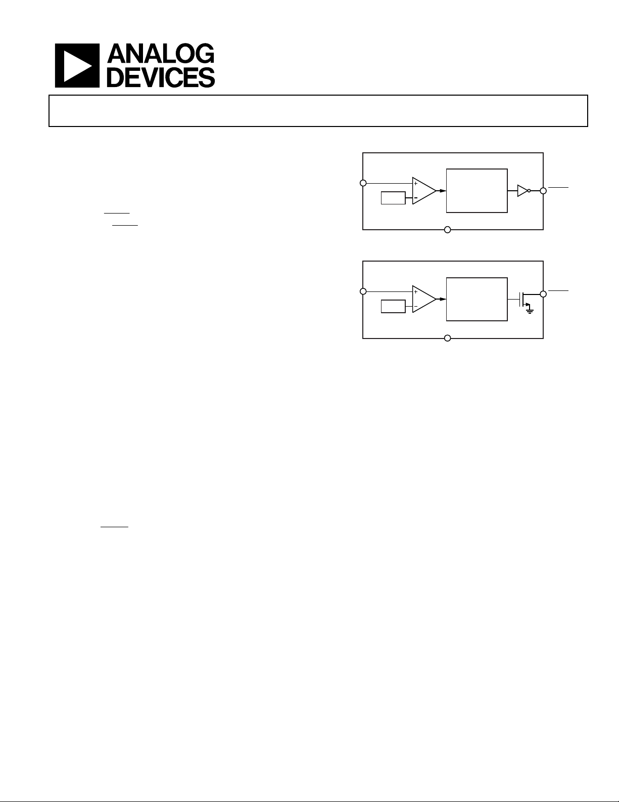
FUNCTIONAL BLOCK DIAGRAMS
ADM6326/ADM6346
V
CC
V
REF
ADM6328/ADM6348
V
CC
V
REF
microprocessor in a reset state until conditions have stabilized.
The reset output remains operational with V
The ADM6326 and ADM6346 have an active low push-pull reset
output. The ADM6328 and ADM6348 have an active low opendrain reset output, which requires an external pull-up resistor.
The ADM6326 and ADM6328 offer a choice of ten reset thresholds
in increments between 2.2 V and 3.08 V, whereas the ADM6346
and ADM6348 offer a choice of 14 reset thresholds between 3.3 V
and 4.63 V.
These devices are available in a 3-lead SOT-23 package and
operate over the extended temperature range of −40°C to +85°C.
GND
Figure 1.
GND
Figure 2.
RESET
GENERATOR
(100ms)
RESET
GENERATOR
(100ms)
as low as 1 V.
CC
RESET
RESET
08052-001
08052-002
Rev. 0
Information furnished by Analog Devices is believed to be accurate and reliable. However, no
responsibility is assumed by Analog Devices for its use, nor for any infringements of patents or other
rights of third parties that may result from its use. Specifications subject to change without notice. No
license is granted by implication or otherwise under any patent or patent rights of Analog Devices.
Trademarks and registered trademarks are the property of their respective owners.
One Technology Way, P.O. Box 9106, Norwood, MA 02062-9106, U.S.A.
Tel: 781.329.4700 www.analog.com
Fax: 781.461.3113 ©2009 Analog Devices, Inc. All rights reserved.
Page 2

ADM6326/ADM6328/ADM6346/ADM6348
TABLE OF CONTENTS
Features .............................................................................................. 1
Applications ....................................................................................... 1
Functional Block Diagrams ............................................................. 1
General Description ......................................................................... 1
Revision History ............................................................................... 2
Specifications ..................................................................................... 3
Absolute Maximum Ratings ............................................................ 4
Thermal Resistance ...................................................................... 4
ESD Caution .................................................................................. 4
REVISION HISTORY
9/09—Revision 0: Initial Version
Pin Configuration and Function Descriptions ..............................5
Typical Performance Characteristics ..............................................6
Theory of Operation .........................................................................7
Reset Output ..................................................................................7
Interfacing to Other Devices .......................................................7
Transient Immunity ......................................................................7
Outline Dimensions ..........................................................................8
Ordering Guide .............................................................................9
Rev. 0 | Page 2 of 12
Page 3
ADM6326/ADM6328/ADM6346/ADM6348
SPECIFICATIONS
TA = −40°C to +85°C, unless otherwise noted. Typical values are at TA = 25°C and VCC = 3 V. Overtemperature limits are guaranteed by design.
Table 1.
Parameter Min Typ Max Unit Test Conditions/Comments
OPERATING VOLTAGE RANGE, VCC 1.0 5.5 V
INPUT CURRENT, ICC 0.5 1.0 µA ADM6326/ADM6328 only, VCC = 3.0 V for VTH ≤
2.93 V, V
1.0 1.75 µA VCC = 5.5 V, no load
RESET THRESHOLD
Threshold Voltage, VTH (See Table 2) VTH − 2.5% VTH V
V
− 1.5% VTH V
TH
Temperature Coefficient 40 ppm/°C
+ 2.5% V
TH
+ 1.5% V TA = 25°C
TH
Hysteresis
ADM6326/ADM6328 6.3 mV
ADM6346/ADM6348 9.5 mV
TIMING CHARACTERISTICS
VCC to Reset Delay (tRD) 20 µs VCC = VTH to (VTH − 100 mV)
Reset Active Timeout Period (tRP) 100 185 280 ms
RESET
OUTPUT VOLTAGE LOW, VOL
RESET
OUTPUT VOLTAGE HIGH, VOH
0.3 V V
0.4 V V
0.8 × V
CC
V ADM6326 only, VCC = 3.2 V, I
0.8 × VCC V ADM6326/ADM6346 only, VCC = 4.5 V,
I
0.8 × VCC V ADM6326/ADM6346 only, VCC = V
I
OPEN-DRAIN
RESET
OUTPUT LEAKAGE CURRENT
0.1 µA
= 3.2 V for VTH > 2.93 V, no load
CC
> 2.1 V, I
CC
≥ 1.2 V, I
CC
= 800 µA, VTH ≤ 4.38 V
SOURCE
= 800 µA, VTH ≥ 4.5 V
SOURCE
= 1.6 mA, reset asserted
SINK
= 100 A, reset asserted
SINK
SOURCE
= 500 µA
TH(MAX)
,
Table 2. Reset Threshold Voltage
Parameter
Min Typ Max Min Max
= 25°C
T
A
RESET THRESHOLD VOLTAGE (VTH)
ADM632x-22 2.167 2.2 2.233 2.145 2.25 V
ADM632x-23 2.285 2.32 2.355 2.262 2.375 V
ADM632x-24 2.364 2.4 2.436 2.34 2.46 V
ADM632x-25 2.462 2.5 2.537 2.437 2.562 V
ADM632x-26 2.591 2.63 2.669 2.564 2.696 V
ADM632x-27 2.66 2.7 2.741 2.633 2.768 V
ADM632x-28 2.758 2.8 2.842 2.73 2.87 V
ADM632x-29 2.886 2.93 2.974 2.857 3.0 V
ADM632x-30 2.955 3.00 3.045 2.925 3.075 V
ADM632x-31 3.034 3.08 3.126 3.003 3.15 V
ADM634x-33 3.25 3.3 3.35 3.217 3.383 V
ADM634x-34 3.349 3.4 3.451 3.315 3.485 V
ADM634x-35 3.447 3.5 3.552 3.412 3.587 V
ADM634x-36 3.546 3.6 3.654 3.51 3.69 V
ADM634x-37 3.644 3.7 3.755 3.607 3.792 V
ADM634x-38 3.743 3.8 3.857 3.705 3.895 V
ADM634x-39 3.841 3.9 3.958 3.802 3.997 V
ADM634x-40 3.94 4.0 4.06 3.9 4.1 V
ADM634x-41 4.038 4.1 4.161 3.997 4.202 V
ADM634x-42 4.137 4.2 4.263 4.095 4.305 V
ADM634x-43 4.235 4.3 4.364 4.192 4.407 V
ADM634x-44 4.314 4.38 4.446 4.27 4.489 V
ADM634x-45 4.432 4.5 4.567 4.387 4.612 V
ADM634x-46 4.56 4.63 4.699 4.514 4.746 V
T
= −40°C to +85°C
A
Unit
Rev. 0 | Page 3 of 12
Page 4
ADM6326/ADM6328/ADM6346/ADM6348
ABSOLUTE MAXIMUM RATINGS
Table 3.
Parameter Rating
Supply Voltage, VCC −0.3 V to +6 V
Input Current, ICC 20 mA
Output Voltage
Push-Pull
Open-Drain
Output Current (
Rate of Rise of VCC
Temperature
Storage −65°C to +155°C
Operating −40°C to +85°C
Soldering (10 sec) 300°C
Stresses above those listed under Absolute Maximum Ratings
may cause permanent damage to the device. This is a stress
rating only; functional operation of the device at these or any
other conditions above those indicated in the operational
section of this specification is not implied. Exposure to absolute
maximum rating conditions for extended periods may affect
device reliability.
RESET
RESET
RESET
)
−0.3 V to (VCC + 0.3 V)
−0.3 V to +6 V
20 mA
100 V/μs
THERMAL RESISTANCE
θJA is specified for the worst-case conditions, that is, a device
soldered in a circuit board for surface-mount packages.
Table 4. Thermal Resistance
Package Type θJA Unit
3-Lead SOT-23 270 °C/W
ESD CAUTION
Rev. 0 | Page 4 of 12
Page 5

ADM6326/ADM6328/ADM6346/ADM6348
PIN CONFIGURATION AND FUNCTION DESCRIPTIONS
ADM6326/
GND
1
ADM6328/
2
RESET
Figure 3. ADM6326/ADM6328/ADM6346/ADM6348 Pin Configuration
Table 5. Pin Function Descriptions
Pin No. Mnemonic Description
1 GND Ground Reference for All Signals; 0 V.
2
RESET
Active Low Logic Output. This pin is low when VCC is less than the reset threshold; it remains low for 185 ms
(typical) after V
becomes greater than the reset threshold.
CC
3 VCC Supply Voltage Being Monitored.
ADM6346/
ADM6348
TOP VIEW
(Not to Scale)
V
3
CC
08052-003
Rev. 0 | Page 5 of 12
Page 6

ADM6326/ADM6328/ADM6346/ADM6348
(
A
A
(
TYPICAL PERFORMANCE CHARACTERISTICS
1.0
0.9
= 5V
0.8
0.7
µA)
0.6
0.5
0.4
0.3
SUPPLY CURRENT
0.2
0.1
0
–40 –20 0 20 40 60 80
V
CC
VCC = 3.3V
VCC = 1.4V
TEMPERAT URE (°C)
Figure 4. Supply Current vs. Temperature
08052-004
280
260
240
220
200
180
160
140
POWER-UP RES ET TIME OUT (ms)
120
100
–40 –20 0 20 40 60 80
TEMPERATURE (°C)
Figure 6. Power-Up Reset Timeout vs. Temperature
08052-007
800
700
600
TION (µs)
500
400
300
200
MAXIMUM TRANSIENT DUR
100
0
1 10 100 1000
RESET THRESHOLD OVERDRI VE, VTH – VCC (mV)
Figure 5. Maximum Transient Duration vs. Reset Threshold Overdrive
250
200
µs)
Y
150
100
VOD = 10mV
= 20mV
V
OD
50
POWER-DOWN RESET DEL
0
–40 –20 0 20 40 8060
08052-006
V
= 200mV
OD
TEMPERATURE (°C)
V
OD
= 100mV
8052-005
Figure 7. Power-Down Reset Delay vs. Temperature
Rev. 0 | Page 6 of 12
Page 7

ADM6326/ADM6328/ADM6346/ADM6348
V
THEORY OF OPERATION
The ADM6326/ADM6328/ADM6346/ADM6348 are designed
to protect the integrity of a system’s operation by ensuring the
proper operation of the system during power-up, power-down,
and brownout conditions. Ultralow supply currents make these
devices particularly suitable for use in low power, portable
equipment.
RESET OUTPUT
The ADM6326 and ADM6346 have an active low, push-pull
reset output, whereas the ADM6328 and ADM6348 have an
active low, open-drain reset output, which requires an external
pull-up resistor. The
down to 1 V.
V
CC
When the ADM6326/ADM6328/ADM6346/ADM6348 are
powered up, the
equal to the
RESET
allows adequate time for the system to power up correctly and
for the power supply to stabilize before any devices are brought out
of reset and are allowed to begin executing instructions. Initializing
a system in this way provides a more reliable startup for micro-
processor systems.
When the monitored voltage falls below its associated threshold
RESET
(V
),
TH
this quickly means that the entire system can be reset at once
before any part of the system’s voltage falls below its recommended
operating voltage. This system reset can avoid dangerous and/or
erroneous operation of a microprocessor based system.
RESET
signal is guaranteed to be valid for
RESET
output remains low for a period typically
active timeout period of 185 ms. This feature
is asserted within 20 μs (typical). Asserting
RESET
INTERFACING TO OTHER DEVICES
The active low, open-drain reset output of the ADM6328 and
ADM6348 makes these devices ideal for integration with devices
such as microprocessors with bidirectional reset pins. Simply
connect the
RESET
the
RESET
output of the ADM6328 or ADM6348 to
input of the microprocessor using a single pull-up
resistor to allow either device to initiate a system reset (see
). Figure 8
CC
V
CC
ADM6328/ADM6348
RESET
GND
Figure 8. Interfacing to a Microprocessor with a Bidirectional Reset Pin
R
PULL-UP
RESET
INPUT
V
CC
MICROPROCESSOR
SYSTEM
GND
TRANSIENT IMMUNITY
To avoid unnecessary resets caused by fast power supply transients,
the ADM6326/ADM6328/ADM6346/ADM6348 provide glitch
immunity from negative-going V
Figure 5 shows the
RESET
comparator overdrive (that is, the
maximum magnitude of negative-going pulses with respect to
the typical threshold) vs. the pulse duration without a reset.
transients.
CC
08052-008
V
CC
RESET
V
CC
1V
0V
V
CC
0V
V
TH
t
RP
RESET
Figure 9.
Timing
V
TH
t
RD
8052-009
Rev. 0 | Page 7 of 12
Page 8

ADM6326/ADM6328/ADM6346/ADM6348
OUTLINE DIMENSIONS
3.04
2.90
2.80
1.40
1.30
1.20
3
1
2.64
2.10
2
1.02
0.95
0.88
0.100
0.013
SEATING
PLANE
0.60
0.45
2.05
1.78
COMPLIANT TO JEDEC STANDARDS TO-236-AB
1.03
0.89
0.51
0.37
1.12
0.89
GAUGE
PLANE
0.180
0.085
0.25
0.54
REF
0.60 MAX
0.30 MIN
011909-C
Figure 10. 3-Lead Small Outline Transistor Package [SOT-23-3]
(RT-3)
Dimensions shown in millimeters
Rev. 0 | Page 8 of 12
Page 9

ADM6326/ADM6328/ADM6346/ADM6348
ORDERING GUIDE
1
Model
ADM6326-22ARTZ-R7
ADM6326-23ARTZ-R7
ADM6326-24ARTZ-R7
ADM6326-25ARTZ-R7
ADM6326-26ARTZ-R7
ADM6326-27ARTZ-R7
ADM6326-28ARTZ-R7
ADM6326-29ARTZ-R7
ADM6326-30ARTZ-R7
ADM6326-31ARTZ-R7
ADM6328-22ARTZ-R7
ADM6328-23ARTZ-R7
ADM6328-24ARTZ-R7
ADM6328-25ARTZ-R7
ADM6328-26ARTZ-R7
ADM6328-27ARTZ-R7
ADM6328-28ARTZ-R7
ADM6328-29ARTZ-R7
ADM6328-30ARTZ-R7
ADM6328-31ARTZ-R7
ADM6346-33ARTZ-R7
ADM6346-34ARTZ-R7
ADM6346-35ARTZ-R7
ADM6346-36ARTZ-R7
ADM6346-37ARTZ-R7
ADM6346-38ARTZ-R7
ADM6346-39ARTZ-R7
ADM6346-40ARTZ-R7
ADM6346-41ARTZ-R7
ADM6346-42ARTZ-R7
ADM6346-43ARTZ-R7
ADM6346-44ARTZ-R7
ADM6346-45ARTZ-R7
ADM6346-46ARTZ-R7
ADM6348-33ARTZ-R7
ADM6348-34ARTZ-R7
ADM6348-35ARTZ-R7
ADM6348-36ARTZ-R7
ADM6348-37ARTZ-R7
ADM6348-38ARTZ-R7
ADM6348-39ARTZ-R7
ADM6348-40ARTZ-R7
ADM6348-41ARTZ-R7
ADM6348-42ARTZ-R7
ADM6348-43ARTZ-R7
ADM6348-44ARTZ-R7
ADM6348-45ARTZ-R7
ADM6348-46ARTZ-R7
1
Contact sales for the availability of nonstandard models.
2
Z = RoHS Compliant Part.
3
Standard model.
`
2, 3
2
2.32 V Push-Pull 3-Lead SOT-23 RT-3 LAR
2
2.4 V Push-Pull 3-Lead SOT-23 RT-3 LAS
2
2.5 V Push-Pull 3-Lead SOT-23 RT-3 LAT
2
2.63 V Push-Pull 3-Lead SOT-23 RT-3 LAU
2
2.7 V Push-Pull 3-Lead SOT-23 RT-3 LAV
2
2.8 V Push-Pull 3-Lead SOT-23 RT-3 LAW
2
2.93 V Push-Pull 3-Lead SOT-23 RT-3 LAX
2
3.0 V Push-Pull 3-Lead SOT-23 RT-3 LAY
2
3.08 V Push-Pull 3-Lead SOT-23 RT-3 LAZ
2
2.2 V Open-Drain 3-Lead SOT-23 RT-3 LB0
2
2.32 V Open-Drain 3-Lead SOT-23 RT-3 LB1
2
2.4 V Open-Drain 3-Lead SOT-23 RT-3 LB2
2
2.5 V Open-Drain 3-Lead SOT-23 RT-3 LB3
2
2.63 V Open-Drain 3-Lead SOT-23 RT-3 LB4
2
2.7 V Open-Drain 3-Lead SOT-23 RT-3 LB5
2, 3
2
2.93 V Open-Drain 3-Lead SOT-23 RT-3 LB7
2
3.0 V Open-Drain 3-Lead SOT-23 RT-3 LB8
2
3.08 V Open-Drain 3-Lead SOT-23 RT-3 LB9
2, 3
2
3.4 V Push-Pull 3-Lead SOT-23 RT-3 LBC
2
3.5 V Push-Pull 3-Lead SOT-23 RT-3 LBD
2
3.6 V Push-Pull 3-Lead SOT-23 RT-3 LBE
2
3.7 V Push-Pull 3-Lead SOT-23 RT-3 LBF
2
3.8 V Push-Pull 3-Lead SOT-23 RT-3 LBG
2
3.9 V Push-Pull 3-Lead SOT-23 RT-3 LBH
2
3.0 V Push-Pull 3-Lead SOT-23 RT-3 LCN
2
4.1 V Push-Pull 3-Lead SOT-23 RT-3 LCP
2
4.2 V Push-Pull 3-Lead SOT-23 RT-3 LCQ
2
4.3 V Push-Pull 3-Lead SOT-23 RT-3 LCR
2
4.38 V Push-Pull 3-Lead SOT-23 RT-3 LCS
2
4.5 V Push-Pull 3-Lead SOT-23 RT-3 LCT
2
4.63 V Push-Pull 3-Lead SOT-23 RT-3 LCU
2
3.3 V Open-Drain 3-Lead SOT-23 RT-3 LCV
2
3.4 V Open-Drain 3-Lead SOT-23 RT-3 LCW
2
3.5 V Open-Drain 3-Lead SOT-23 RT-3 LCX
2
3.6 V Open-Drain 3-Lead SOT-23 RT-3 LCY
2
3.7 V Open-Drain 3-Lead SOT-23 RT-3 LCZ
2
3.8 V Open-Drain 3-Lead SOT-23 RT-3 LD0
2
3.9 V Open-Drain 3-Lead SOT-23 RT-3 LD1
2
3.0 V Open-Drain 3-Lead SOT-23 RT-3 LD2
2
4.1 V Open-Drain 3-Lead SOT-23 RT-3 LD3
2
4.2 V Open-Drain 3-Lead SOT-23 RT-3 LD4
2
4.3 V Open-Drain 3-Lead SOT-23 RT-3 LD5
2
4.38 V Open-Drain 3-Lead SOT-23 RT-3 LD6
2
4.5 V Open-Drain 3-Lead SOT-23 RT-3 LD7
2, 3
Typ ica l Th res hol d
Voltage (T
2.2 V Push-Pull 3-Lead SOT-23 RT-3 LAQ
2.8 V Open-Drain 3-Lead SOT-23 RT-3 LB6
3.3 V Push-Pull 3-Lead SOT-23 RT-3 LBA
4.63 V Open-Drain 3-Lead SOT-23 RT-3 LD8
= 25°C)
A
RESET
Output
Structure Package Description Package Option Branding
Rev. 0 | Page 9 of 12
Page 10

ADM6326/ADM6328/ADM6346/ADM6348
NOTES
Rev. 0 | Page 10 of 12
Page 11

ADM6326/ADM6328/ADM6346/ADM6348
NOTES
Rev. 0 | Page 11 of 12
Page 12

ADM6326/ADM6328/ADM6346/ADM6348
NOTES
©2009 Analog Devices, Inc. All rights reserved. Trademarks and
registered trademarks are the property of their respective owners.
D08052-0-9/09(0)
Rev. 0 | Page 12 of 12
 Loading...