

Page 1

High Precision
FEATURES
Laser trimmed to high accuracy
10.000 V ±5 mV (L and U models)
Trimmed temperature coefficient
5 ppm/°C maximum, 0°C to 70°C (L model)
10 ppm/°C maximum, −55°C to +125°C (U model)
Excellent long-term stability
25 ppm/1000 hrs (noncumulative)
−10 V reference capability
Low quiescent current: 1.0 mA maximum
10 mA current output capability
3-pin TO-5 package
MIL-STD-883 compliant versions available
GENERAL DESCRIPTION
The AD581 is a 3-pin, temperature compensated, monolithic,
band gap voltage reference that provides a precise 10.00 V output
from an unregulated input level ranging from 12 V to 30 V.
Laser wafer trimming (LWT) is used to trim both the initial
error at +25°C as well as the temperature coefficient, resulting
in high precision performance previously available only in expensive hybrids or oven regulated modules. The 5 mV initial error
tolerance and 5 ppm/°C guaranteed temperature coefficient of
the AD581L is available in a monolithic voltage reference.
The band gap circuit design used in the AD581 offers several
advantages over classical Zener breakdown diode techniques.
Most important, no external components are required to
achieve full accuracy and significant stability to low power
systems. In addition, total supply current to the device,
including the output buffer amplifier (which can supply up
to 10 mA) is typically 750 A. The long-term stability of the
band gap design is equivalent to selected Zener reference
diodes.
The AD581 is recommended for use as a reference for 8-, 10-
or 12-bit digital-to-analog converters (DACs) that require an
external precision reference. The device is also ideal for all types
of analog-to-digital converters (ADCs) up to 14-bit accuracy,
either successive approximation or integrating designs, and can
generally offer better performance than that provided by standard
self-contained references.
10 V IC Reference
AD581
FUNCTIONAL BLOCK DIAGRAM
+V
S
V
OUT
AD581
GND
TO-5
BOTTOM VIEW
Figure 1.
The AD581J, AD581K, and AD581L are specified for operation
from 0°C to 70°C; the AD581S, AD581T, and AD581U are
specified for the −55°C to +125°C range. All grades are
packaged in a hermetically sealed 3-pin TO-5 metal can.
PRODUCT HIGHLIGHTS
1. Laser trimming of both initial accuracy and temperature
coefficient results in very low errors over temperature
without the use of external components. The AD581L has
a maximum deviation from 10.000 V of ±7.25 mV from
0°C to 70°C, whereas the AD581U guarantees ±15 mV
maximum total error without external trims from −55°C
to +125°C.
2. Because the laser trimming is done on the wafer prior to
separation into individual chips, the AD581 is extremely
valuable to hybrid designers for its ease of use, lack of
required external trims, and inherent high performance.
3. The AD581 can also be operated in a 2-pin Zener mode to
provide a precision −10 V reference with just one external
resistor to the unregulated supply. The performance in this
mode is nearly equal to that of the standard 3-pin configuration.
4. Advanced circuit design using the band gap concept allows
the AD581 to give full performance with an unregulated
input voltage down to 13 V. With an external resistor, the
device operates with a supply as low as 11.4 V.
5. The AD581 is available in versions compliant with
MILSTD-883. Refer to the military datasheet for detailed
specifications.
08014-001
Rev. C
Information furnished by Analog Devices is believed to be accurate and reliable. However, no
responsibility is assumed by Analog Devices for its use, nor for any infrin gements of patents or other
rights of third parties that may result from its use. Specifications subject to change without notice. No
license is granted by implication or otherwise under any patent or patent rights of Analog Devices.
Trademarks and registered trademarks are the property of their respective owners.
One Technology Way, P.O. Box 9106, Norwood, MA 02062-9106, U.S.A.
Tel: 781.329.4700 www.analog.com
Fax: 781.461.3113 ©2009 Analog Devices, Inc. All rights reserved.
Page 2

AD581
TABLE OF CONTENTS
Features .............................................................................................. 1
Functional Block Diagram .............................................................. 1
General Description ......................................................................... 1
Product Highlights ........................................................................... 1
Revision History ............................................................................... 2
Specifications ..................................................................................... 3
Absolute Maximum Ratings ............................................................ 5
ESD Caution .................................................................................. 5
Applying the AD581 ......................................................................... 6
Voltage Variation vs. Temperature ............................................. 6
REVISION HISTORY
4/09—Rev. B to Rev. C
Updated Format .................................................................. Universal
Changes to Table 1 ............................................................................ 3
Changes to Figure 2 .......................................................................... 6
Changes to Figure 11 ........................................................................ 8
Changes to 10 V Reference with Multiplying CMOS DACs
or ADCs Section ............................................................................... 9
Changes to Precision 12-Bit DAC Reference Section .................. 9
Changes to Figure 13 ........................................................................ 9
Changes to Figure 15 and Figure 16 ............................................. 10
Updated Outline Dimensions ....................................................... 11
Changes to Ordering Guide .......................................................... 11
Output Current Characteristics ...................................................7
Dynamic Performance ..................................................................7
Precision High Current Supply ...................................................8
Connection for Reduced Primary Supply ..................................8
The AD581 as a Current Limiter .....................................................9
Negative 10 V Reference ...............................................................9
10 V Reference with Multiplying CMOS DACs or ADCs .......9
Precision 12-Bit DAC Reference .................................................9
Outline Dimensions ........................................................................ 11
Ordering Guide ........................................................................... 11
Rev. C | Page 2 of 12
Page 3
AD581
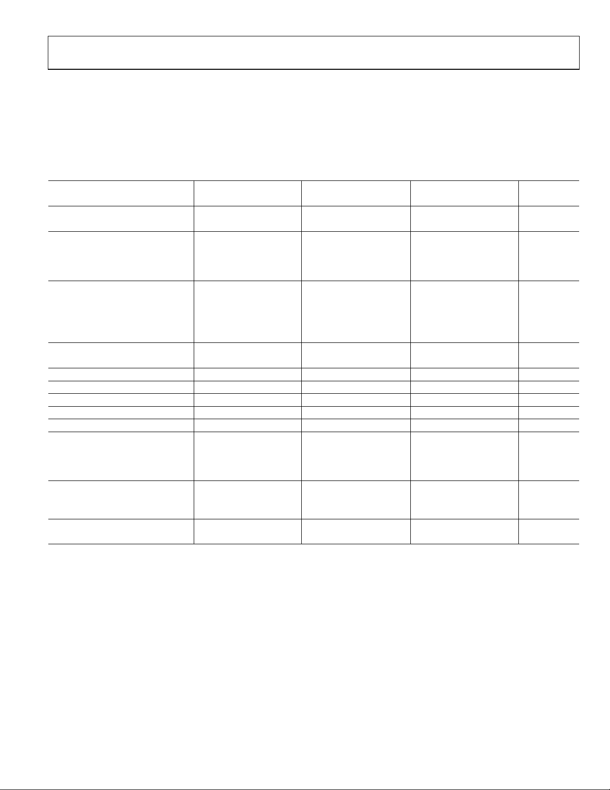
SPECIFICATIONS
@ VIN = +15 V and TA = +25°C.
Specifications shown in boldface are tested on all production units at final electrical test. Results from those tests are used to calculate
outgoing quality levels. All minimum and maximum specifications are guaranteed, although only those shown in boldface are tested on
all production units.
Table 1.
AD581J AD581K AD581L
Model
OUTPUT VOLTAGE TOLERANCE
(Error from Nominal 10,000 V Output)
±30
±10
±5
OUTPUT VOLTAGE CHANGE
Maximum Deviation from +25°C
Value, T
MIN
to T
MAX
±13.5
±6.75
±2.25
Temperature Coefficient 30 15 5 ppm/°C
LINE REGULATION
15 V ≤ VIN ≤ 30 V
3.0
3.0
3.0
(0.002) (0.002) (0.002) %/V
13 V ≤ VIN ≤ 15 V
1.0
1.0
1.0
(0.005) (0.005) (0.005) %/V
LOAD REGULATION
0 ≤ I
≤ 5 mA 200
OUT
QUIESCENT CURRENT 0.75
TURN-ON SETTLING TIME TO 0.1%
1
200 200 200 μs
500
1.0
200
0.75
500
1.0
200
0.75
500
1.0
NOISE (0.1 Hz TO 10 Hz) 40 40 40 μV (p-p)
LONG-TERM STABILITY 25 25 25 ppm/1000 hr
SHORT-CIRCUIT CURRENT 30 30 30 mA
OUTPUT CURRENT
Source @ +25°C 10 10 10 mA
Source T
Sink T
MIN
to T
MIN
to T
5 5 5 mA
MAX
5 5 5 μA
MAX
TEMPERATURE RANGE
Specified 0 70 0 70 0 70 °C
Operating −65 +150 −65 +150 −65 +150 °C
PACKAGE OPTION
2
TO-5 (H-03B) AD581JH AD581KH AD581LH
1
See Figure 7.
2
H indicates the hermetic metal can.
Units Min Typ Max Min Typ Max Min Typ Max
mV
mV
mV
mV
μV/mA
mA
Rev. C | Page 3 of 12
Page 4
AD581
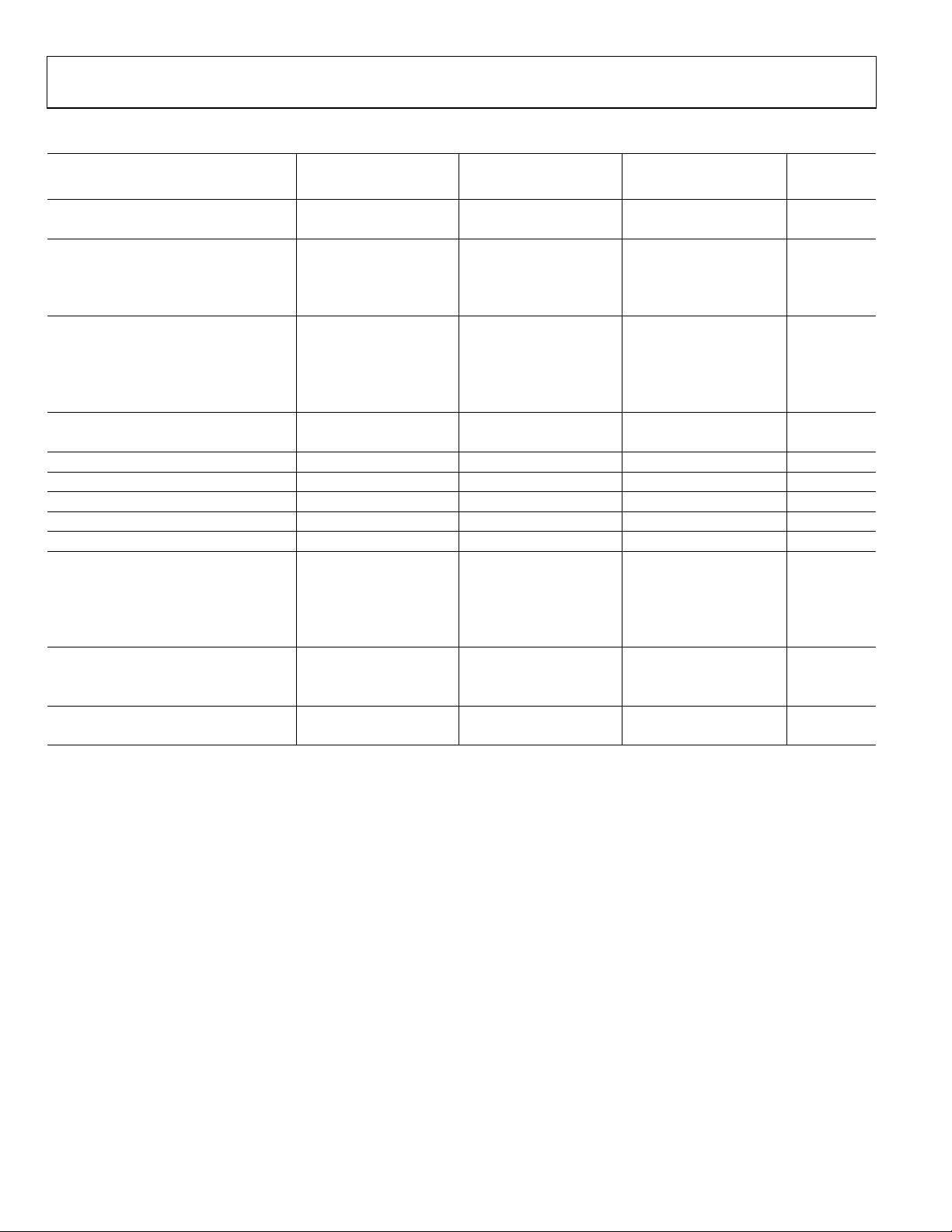
Table 2.
AD581S AD581T AD581U
Model
OUTPUT VOLTAGE TOLERANCE
(Error from Nominal 10,000 V Output)
±30
±10
±5
OUTPUT VOLTAGE CHANGE
Maximum Deviation from +25°C
Value, T
MIN
to T
MAX
±30
±15
±10
Temperature Coefficient 30 15 10 ppm/°C
LINE REGULATION
15 V ≤ VIN ≤ 30 V
3.0
3.0
3.0
(0.002) (0.002) (0.002) %/V
13 V ≤ VIN ≤ 15 V
1.0
1.0
1.0
(0.005) (0.005) (0.005) %/V
LOAD REGULATION
0 ≤ I
≤ 5 mA 200
OUT
QUIESCENT CURRENT 0.75
TURN-ON SETTLING TIME TO 0.1%
1
200 200 200 μs
500
1.0
200
0.75
500
1.0
200
0.75
500
1.0
NOISE (0.1 Hz TO 10 Hz) 40 40 40 μV (p-p)
LONG-TERM STABILITY 25 25 25 ppm/1000 hr
SHORT-CIRCUIT CURRENT 30 30 30 mA
OUTPUT CURRENT
Source @ +25°C 10 10 10 mA
Source T
Sink T
MIN
to T
MIN
to T
5 5 5 mA
MAX
200 200 200 μA
MAX
Sink −55°C to +85°C 5 5 5 mA
TEMPERATURE RANGE
Specified −55 +125 −55 +125 −55 +125 °C
Operating −65 +150 −65 +150 −65 +150 °C
PACKAGE OPTION
2
TO-5 (H-03B) AD581SH AD581TH AD581UH
1
See Figure 7.
2
H indicates hermetic metal can.
Units Min Typ Max Min Typ Max Min Typ Max
mV
mV
mV
mV
μV/mA
mA
Rev. C | Page 4 of 12
Page 5

AD581
ABSOLUTE MAXIMUM RATINGS
Table 3.
Parameter Rating
Input Voltage 40 V
Power Dissipation @ +25°C 600 mW
Operating Junction Temperature Range −55°C to +150°C
Lead Temperature (Soldering 10 sec) +300°C
Thermal Resistance
Junction-to-Ambient 150°C/W
Stresses above those listed under Absolute Maximum Ratings
may cause permanent damage to the device. This is a stress
rating only; functional operation of the device at these or any
other conditions above those indicated in the operational
section of this specification is not implied. Exposure to absolute
maximum rating conditions for extended periods may affect
device reliability.
ESD CAUTION
Rev. C | Page 5 of 12
Page 6

AD581
V
V
APPLYING THE AD581
The AD581 is easy to use in virtually all precision reference
applications. The three pins are simply: primary supply, ground,
and output, with the case grounded. No external components
are required even for high precision applications; the degree of
desired absolute accuracy is achieved simply by selecting the
required device grade. The AD581 requires less than 1 mA quiescent current from an operating supply range of 13 V to 30 V.
13V TO 30
R40 R41
Q10
Q16 Q13
C52
C51
Q6
Q12
Q11
Q14
Q20
Q15
V+
Q7
Q8
R42
10V
R34
R37
Q5
+V
S
V
AD581
OUT
GND
10V
08014-002
Figure 2. Pin Configuration (Bottom View)
An external fine trim may be desired to set the output level to
exactly 10.000 V within less than a millivolt (calibrated to a
main system reference). System calibration may also require a
reference slightly different from 10.00 V. In either case, the
optional trim circuit shown in Figure 3 can offset the output by
up to ±30 mV (with the 22 resistor), if needed, with minimal
effect on other device characteristics.
+15
TRIM
R
RANGE
22Ω ±30mV 3.5ppm/°C
12Ω ±10mV 2.0ppm/°C
3.9Ω ±5mV 0.6ppm/°C
MAX
Δ TCR
6.8kΩ
10kΩ
AD581
+V
GND
S
V
OUT
R
+10V
C50
R32R33
R35
Q4Q3
R39
Q1Q2
R31
R36R30
V–
8014-004
Figure 4. Simplified Schematic
VOLTAGE VARIATION vs. TEMPERATURE
Some confusion exists in the area of defining and specifying
reference voltage error over temperature. Historically, references
have been characterized using a maximum deviation per degree
Celsius; that is, 10 ppm/°C. However, because of nonlinearities
in temperature characteristics, which originated in standard
Zener references (such as S-type characteristics) manufacturers
opt for the maximum limit error band approach to specify devices.
This technique involves measurement of the output at three,
five, or more different temperatures to guarantee that the output
voltage falls within the given error band. The temperature characteristic of the AD581 consistently follows the S-curve shown in
Figure 5. Three-point measurement of each device guarantees
the error band over the specified temperature range.
10.005
–15V
4.3kΩ
08014-003
Figure 3. Optional Fine Trim Configuration
(V)
10.000
OUT
V
9.995
–50–55 –40 –30 –20 –10 0 10 20 30 40 50 60 70 80 90 100 110 120 125
TEMPERATURE ( °C)
08014-005
Figure 5. Typical Temperature Characteristic
Rev. C | Page 6 of 12
Page 7

AD581
V
The error band which is guaranteed with the AD581 is the
maximum deviation from the initial value at +25°C; this error
band is of more use to a designer than one which simply guarantees
the maximum total change over the entire range (that is, in the
latter definition, all of the changes could occur in the positive
direction). Thus, with a given grade of the AD581, the designer
can easily determine the maximum total error from initial tolerance plus temperature variation (for example, for the AD581T, the
initial tolerance is ±10 mV, the temperature error band is ±15 mV,
thus the unit is guaranteed to be 10.000 V ±25 mV from −55°C
to +125°C).
OUTPUT CURRENT CHARACTERISTICS
The AD581 has the capability to either source or sink current
and provide good load regulation in either direction, although
it has better characteristics in the source mode (positive current
into the load). The circuit is protected for shorts to either positive
supply or ground. The output voltage vs. output current characteristics of the device are shown in Figure 6. Source current
is displayed as negative current in the figure; sink current is
positive. Note that the short-circuit current (that is, 0 V output)
is about 28 mA; when shorted to +15 V, the sink current goes to
about 20 mA.
12
10.03V
11V
OUTPUTINPUT
10V
20V
10V
0V
0 50 100 150 200 250
SETTLING TIME (µs)
10.02V
10.01V
10.00V
08014-007
OUTPUT
Figure 7. Output Settling Characteristic
1000
NOISE SPE CT RAL DENSITY ( nV/ Hz)
100
TOTAL NOISE (µV rms) UP
10
TO SPECIFIED FREQUENCY
+VS = 15V
14
= 25°C
T
A
12
10
8
6
OUTPUT VOLTAGE (V)
4
2
0
–20 –15 –10 –5 0 5 10 15 20
SOURCE SINK
OUTPUT CURRENT (mA)
08014-006
Figure 6. Output Voltage vs. Sink and Source Current
DYNAMIC PERFORMANCE
Many low power instrument manufacturers have been increasingly concerned with the turn-on characteristics of the
components used in their systems. Fast turn-on components often
enable the end user to keep power off when not needed, and yet
respond quickly when the power is turned on for operation.
Figure 7 displays the turn-on characteristic of the AD581. This
characteristic is generated from a cold start operation and represents the true turn-on waveform after an extended period with
the supplies off. The figure shows both the coarse and fine transient
characteristics of the device; the total settling time to within
±10 mV is about 180 s, and there is no long thermal tail
appearing after the point.
1
10 1M
100 1k 10k 100k
FREQUENCY (Hz)
Figure 8. Spectral Noise Density and Total rms Noise vs. Frequency
1000
900
800
700
SUPPLY CURRENT ( µ A)
600
500
–50–55 –40 –30 –20 –10 0 10 20 30 40 50 60 70 80 90 100 110 120 125
Figure 9. Quiescent Current vs. Temperature
1.5µA/°C
TEMPERATURE ( °C)
08014-008
08014-009
Rev. C | Page 7 of 12
Page 8

AD581
V
V
PRECISION HIGH CURRENT SUPPLY CONNECTION FOR REDUCED PRIMARY SUPPLY
The AD581 can be easily connected with power pnp or power
Darlington pnp devices to provide much greater output current
capability. The circuit shown in Figure 10 delivers a precision
10 V output with up to 4 A supplied to the load. The 0.1 F
capacitor is required only if the load has a significant capacitive
component. If the load is purely resistive, improved high frequency
supply rejection results from removing the capacitor.
≥ 15
IN
470Ω
2N6040
0.1µF
+V
S
V
AD581
OUT
GND
Figure 10. High Current Precision Supply
V
OUT
10V @ 4A
8014-010
Whereas line regulation is specified down to 13 V, the typical
AD581 works as specified ≤12 V. The current sink capability
allows even lower supply voltage capability such as operation
from 12 V ±5% as shown in Figure 11. The 560 resistor reduces
the current supplied by the AD581 to a manageable level at a
full 5 mA load. Note that the other band gap references, without
current sink capability, may be damaged by use in this circuit
configuration.
12V ±5%
+V
S
560Ω 5%
AD581
GND
Figure 11. 12 V Supply Connection
10V @ 0mA TO 5mA
V
OUT
08014-011
Rev. C | Page 8 of 12
Page 9

AD581
A
A
V
THE AD581 AS A CURRENT LIMITER
The AD581 represents an alternative to current limiter diodes
that require factory selection to achieve a desired current. This
approach often results in temperature coefficients of 1%/°C.
The AD581 approach is not limited to a defined set current
limit; it can be programmed from 0.75 mA to 5 mA with the
insertion of a single external resistor. Of course, the minimum
voltage required to drive the connection is 13 V. The AD580,
which is a 2.5 V reference, can be used in this type of circuit
with compliance voltage down to 4.5 V.
+V
S
D581
GND
BOTTOM VI EW OF
10V PRECISION
REFERENCE CIRCUIT
IN TO-5 CASE
V
OUT
10V =
R
LOAD
Figure 12. A Two-Component Precision Current Limiter
NEGATIVE 10 V REFERENCE
The AD581 can also be used in a 2-pin Zener mode to provide a
precision −10.00 V reference. As shown in Figure 13, the +V
V
pins are connected together to the high supply (in this
OUT
case, ground). The ground pin is connected through a resistor
to the negative supply. Thus, the output is taken from the
ground pin instead of V
AD581 in this mode, a typical unit shows a 2 mV increase in
output level over that produced in the 3-pin mode. Note also
that the effective output impedance in this connection increases
from 0.2 typical to 2 . It is essential to arrange the output
load and the supply resistor, R
the AD581 is always between 1 mA and 5 mA. For operation to
+125°C, the net current should be between 2 mA and 5 mA. The
temperature characteristics and long-term stability of the device
are essentially the same as that of a unit used in the standard
3-pin mode.
The AD581 can also be used in a 2-pin mode to develop a
positive reference. +V
positive supply through an appropriate supply resistor. The
performance characteristics are similar to those of the negative
2-pin connection. The only advantage of this connection over
the standard 3-pin connection is that a lower primary supply
can be used, as low as 10.5 V. This type of operation requires considerable attention to load and primary supply regulation to
maintain the AD581 within its regulating range of 1 mA to 5 mA
(2 mA to 5 mA for operation beyond +85°C).
. With 1 mA flowing through the
OUT
, so that the net current through
S
and V
S
are tied together and to the
OUT
10V
~ ___ + 0.75mA
i =
R
08014-012
and
S
NALOG
GND
V
REF
–10V
8014-013
0.1µF
+V
AD581
GND
1.2kΩ 5%
–15V
S
V
OUT
Figure 13. 2-Pin −10 V Reference
10 V REFERENCE WITH MULTIPLYING CMOS DACs OR ADCs
The AD581 is ideal for application with the entire AD7533
series of 10- and 12-bit multiplying CMOS DACs, especially for
low power applications. It is equally suitable for the AD7574
8-bit ADC. In the standard hook-up, as shown in Figure 15, the
+10 V reference is inverted by the amplifier/DAC configuration
to produce a 0 V to −10 V range. If an OP1177 amplifier is used,
total quiescent supply current is typically 2 mA. If a 0 V to +10 V
full-scale range is desired, the AD581 can be connected to the
CMOS DAC in its −10 V Zener mode, as shown in Figure 13
(the −10 V
output is connected directly to the V
REF
REF IN
of the
CMOS DAC). The AD581 is normally used in the −10 V mode
with the AD7574 to give a 0 V to +10 V ADC range. This is
shown in Figure 15. Bipolar output applications and other
operating details can be found in the data sheets for the CMOS
products.
+15
+10V
V
REF IN
4
5
13
15 14
3
GND
16
1
2
R
FEEDBACK
I
OUT1
I
OUT2
+15V
–15V
Figure 14. Low Power 10-Bit CMOS DAC Application
V
OUT
0V TO –10V
08014-014
DIGITAL
INPUT
AD581
BIT 1 (MSB)
BIT 10 (LSB)
PRECISION 12-BIT DAC REFERENCE
AD565A, like most DACs, is designed to operate with a +10 V
reference element. In the AD565A, this 10 V reference voltage is
converted into a reference current of approximately 0.5 mA via
the internal 19.95 k resistor (in series with the external 100
trimmer). The gain temperature coefficient of the AD565A is
primarily governed by the temperature tracking of the 19.95 k
resistor and the 5 kΩ to10 kΩ span resistors; gain TC is guaranteed to 3 ppm/°C. Thus, using the AD581L (at 5 ppm/°C) as the
Rev. C | Page 9 of 12
Page 10

AD581
V
–15V
–15V
V
10 V reference guarantees a maximum full-scale temperature
coefficient of 8 ppm/°C over the commercial range. The 10 V
reference also supplies the normal 1 mA bipolar offset current
through the 9.95 kΩ bipolar offset resistor. Consequently, the
bipolar offset TC depends only on TC matching of the bipolar
offset resistor to the input reference resistor and is guaranteed
to 3 ppm/°C.
+5V/+15
24
23
BIT 1
BIT 222BIT 321BIT 420BIT 519BIT 618BIT 717BIT 816BIT 9
(MSB)
PNP LOGIC SWITCHES AND LEVEL SHIFTERS
Figure 16. Precision 12-Bit DAC
+15V
+V
S
AD581
GND
0.1µF
CONTROL AMP
SUMMING
JUNCTION
GAIN ADJ.
10V
V
OUT
100Ω, 15T
BIPOLAR O FFSET ADJ.
100Ω, 15T
R2
A
R1
0.1µF
4
5
3
19.95kΩ
216
0.5mA
CONTROL
A
AMP
–15V
GND
V
OUT
0.1µF
R3
1.2kΩ
5%
–10V REF
SIGNAL
INPUT
0V TO +10V
GAIN TRIM
R2 2kΩ
R1 1kΩ 10%
ANALOG
SUPPLY
RETURN
AD581
+V
S
1
R1 AND R2 CAN BE OMITTED IF GAIN TRIM
IS NOT REQUIRED.
Figure 15. AD581 as −10 V Reference for CMOS ADC
15
13
5kΩ
(LSB)
BIT 1014BIT 11
AD565A
(8kΩ)
BIT 12
5kΩ
(8kΩ)
9.950kΩ
(15.95k)
A = ANALOG GROUND
+5
1
1 18
AD7574
(TOP VIEW)
2
3
1
4
5
GROUND
INTERTIE
ANALOG
GROUND
11
10
R3
3.0MΩ
2
OP1177
3
+15V
–15V
UNIPOLAR
OFFSET ADJ.
9
12
8
7
R4
20kΩ, 15T
DIGITAL
SUPPLY
RETURN
OP AMP
OUTPUT
08014-015
08014-016
Rev. C | Page 10 of 12
Page 11

AD581
OUTLINE DIMENSIONS
0.185 (4.70)
0.165 (4.19)
0.500 (12.70)
MIN
0.100 (2.54) T YP
3
0.200
(5.08)
0.335 (8.51)
0.305 (7.75)
0.370 (9.40)
0.335 (8.51)
0.030 (0.76) M AX
CONTROLL ING DIMENSIONS ARE IN I NCHES ; M ILLIM ETER DIMENSI ONS
(IN PARENTHESES) ARE ROUNDED-OFF INCH EQUI VALENTS FOR
REFERENCE ONL Y AND ARE NO T APPROPRIAT E FOR USE IN DESIGN.
0.019 (0.48)
0.016 (0.41)
BASE & SEATING P LANE
TYP
2
1
45°
0.045 (1.14)
0.029 (0.74)
0.034 (0.86)
0.028 (0.71)
030309-A
Figure 17. 3-Pin Metal Header Package [TO-5]
(H-03B)
Dimensions shown in inches and (millimeters)
ORDERING GUIDE
Model Temperature Range Package Description Package Option
AD581JH
AD581KH
AD581LH
AD581SH
AD581TH
AD581UH
1
RoHS compliant model as of Date Code 0713.
1
0°C to +70°C 3-Pin Metal Header Package (TO-5) H-03B
1
0°C to +70°C 3-Pin Metal Header Package (TO-5) H-03B
1
0°C to +70°C 3-Pin Metal Header Package (TO-5) H-03B
1
−55°C to +125°C 3-Pin Metal Header Package (TO-5) H-03B
1
−55°C to +125°C 3-Pin Metal Header Package (TO-5) H-03B
1
−55°C to +125°C 3-Pin Metal Header Package (TO-5) H-03B
Rev. C | Page 11 of 12
Page 12

AD581
NOTES
©2009 Analog Devices, Inc. All rights reserved. Trademarks and
registered trademarks are the property of their respective owners.
D08014-0-4/09(C)
Rev. C | Page 12 of 12
 Loading...