

Page 1
3-Channel Digital Potentiometer with
FEATURES
3 channels:
Dual 512-position
Single 128-position
25 kΩ or 250 kΩ full-scale resistance
Low temperature coefficient:
Potentiometer divider 15 ppm/°C
Rheostat mode 35 ppm/°C
Nonvolatile memory retains wiper settings
Permanent memory write protection
Linear increment/decrement
±6 dB increment/decrement
2
C-compatible serial interface
I
2.7 V to 5.5 V single-supply operation
±2.25 V to ±2.75 V dual-supply operation
Power-on reset time
256 bytes general-purpose user EEPROM
11 bytes RDAC user EEPROM
GBIC and SFP compliant EEPROM
100-year typical data retention at T
APPLICATIONS
Mechanical potentiometer replacement
RGB LED backlight control
White LED brightness adjustment
Programmable gain and offset control
Programmable filters
GENERAL DESCRIPTION
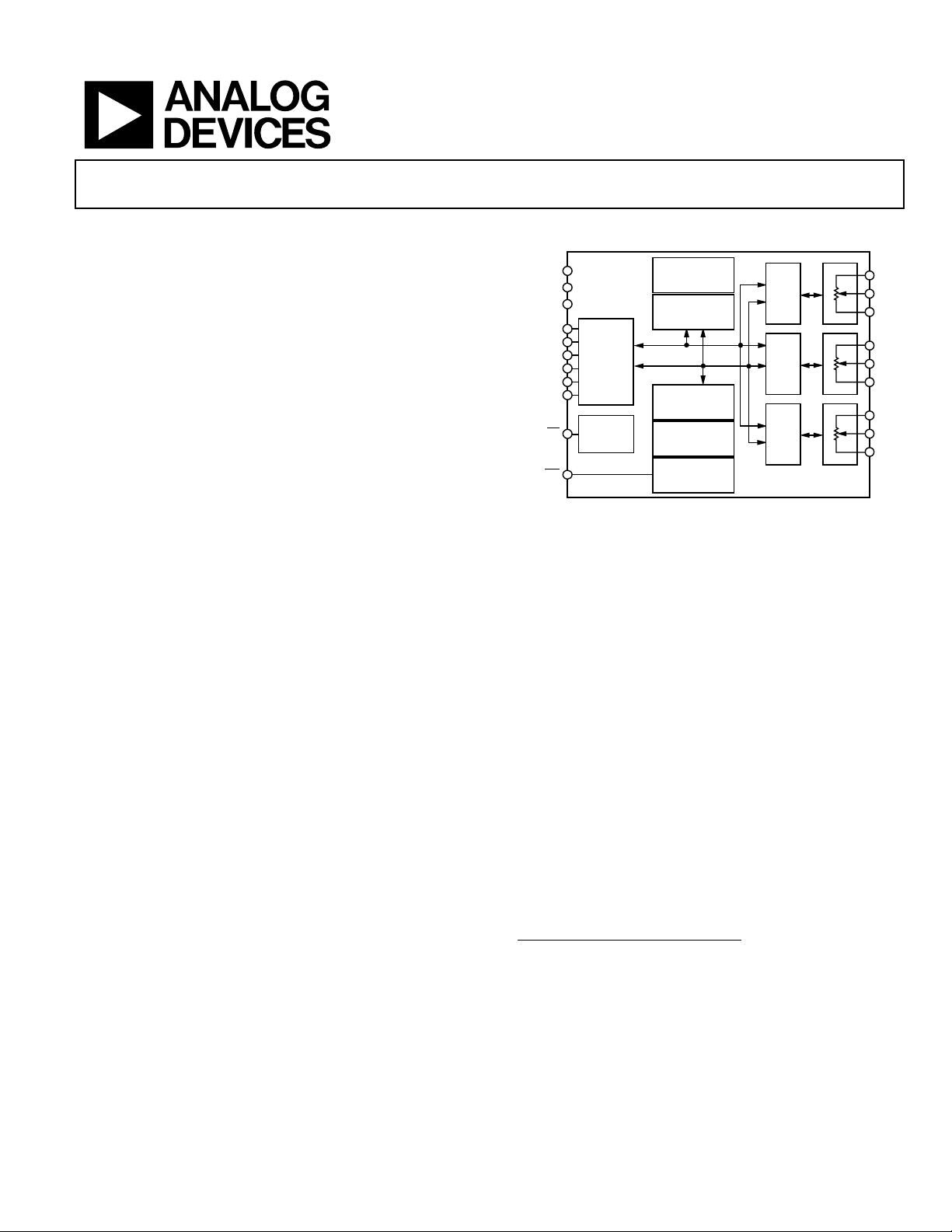
The AD5255 provides dual 512-position and a single
128-position digitally controlled variable resistors
TSSOP package. This device performs the same electronic
adjustment function as a potentiometer, trimmer, or variable
resistor. Each VR offers a completely programmable value of
resistance between the A terminal and the wiper or the B
terminal and the wiper. The fixed A-to-B terminal resistance of
25 kΩ or 250 kΩ has a 1% channel-to-channel matching
tolerance and a nominal temperature coefficient of 35 ppm/°C.
Wiper position programming, EEPROM
writing is conducted via the standard 2-wire I
vious/default wiper position settings can be stored in memory,
and refreshed upon system power-up.
= 55°C
A
1
(VR) in a
2
reading, and EEPROM
2
C interface. Pre-
Nonvolatile Memory
AD5255
FUNCTIONAL BLOCK DIAGRAM
V
V
GND
SCL
SDA
A0_RDAC
A1_RDAC
A0_E
A1_E
WP
DD
SS
RS
2
I
C
SERIAL
INTERFACE
POWER-ON
RESET
256 BYTES
USER
EEPROM
32 BYTES
RDAC
EEPROM
DATA
CONTROL
COMMAND
DECODE
LOGIC
ADDRESS
DECODE
LOGIC
DECODE
LOGIC
Figure 1.
Additional features of the AD5255 include preprogrammed
linear and logarithmic increment/decrement wiper changing.
The actual resistor tolerances are stored in EEPROM so that the
actual end-to-end resistance is known, which is valuable for
calibration in precision applications.
The AD5255 is available in a 24-lead TSSOP package. All parts
are guaranteed to operate over the extended industrial temperature range of −40°C to +85°C.
1
The terms programmable resistor, variable resistor, RDAC, and digital
potentiometer are used interchangeably.
2
The terms nonvolatile memory, EEMEM, and EEPROM are used
interchangeably.
RDAC0
REGISTER
RDAC1
REGISTER
RDAC2
REGISTER
RDAC0
9 BIT
RDAC1
9 BIT
RDAC2
7 BIT
A0
A0
A0
W0
W0
W0
B0
B0
B0
A1
A1
A1
W1
W1
W1
B1
B1
B1
A2
A2
A2
W2
W2
W2
B2
B2
B2
04555-0-001
Rev. 0
Information furnished by Analog Devices is believed to be accurate and reliable.
However, no responsibility is assumed by Analog Devices for its use, nor for any
infringements of patents or other rights of third parties that may result from its use.
Specifications subject to change without notice. No license is granted by implication
or otherwise under any patent or patent rights of Analog Devices. Trademarks and
registered trademarks are the property of their respective owners.
One Technology Way, P.O. Box 9106, Norwood, MA 02062-9106, U.S.A.
Tel: 781.329.4700
Fax: 781.326.8703 © 2004 Analog Devices, Inc. All rights reserved.
www.analog.com
Page 2

AD5255
TABLE OF CONTENTS
Electrical Characteristics ................................................................. 3
Digital Input/Output Configuration........................................ 16
Electrical Characteristics ................................................................. 5
Absolute Maximum Ratings............................................................ 6
ESD Caution.................................................................................. 6
Pin Configuration and Function Descriptions............................. 7
Typical Performance Characteristics ............................................. 8
Interface Descriptions.................................................................... 10
2
I
C Interface ................................................................................ 10
EEPROM Interface..................................................................... 11
RDAC I
Theory of Operation ...................................................................... 15
Linear Increment and Decrement Commands ......................15
Logarithmic Taper Mode Adjustment (±6 dB/step).............. 15
Using Additional Internal Nonvolatile EEPROM.................. 16
2
C Interface.................................................................... 12
REVISION HISTORY
Multiple Devices on One Bus ................................................... 16
Level Shift for Bidirectional Communication ........................ 16
Terminal Voltage Operation Range ......................................... 16
Power-Up Sequence ................................................................... 17
Layout and Power Supply Biasing ............................................ 17
RDAC Structure.......................................................................... 17
Calculating the Programmable Resistance ............................. 17
Programming the Potentiometer Divider............................... 18
Applications..................................................................................... 19
Laser Diode Driver (LDD) Calibration................................... 19
Outline Dimensions....................................................................... 20
Ordering Guide .......................................................................... 20
7/04—Revision 0: Initial Version
Rev. 0 | Page 2 of 20
Page 3

AD5255
ELECTRICAL CHARACTERISTICS
Single supply: VDD = 2.7 V to 5.5 V and −40°C < TA < +85°C, unless otherwise noted.
Dual supply: V
Table 1.
Parameter Symbol Conditions Min Typ
DC CHARACTERISTICS,
RHEOSTAT MODE
Resistor Differential Nonlinearity
Resistor Integral Nonlinearity
Resistance Temperature Coefficent
Wiper Resistance R
Channel Resistance Matching ∆R
Nominal Resistor Tolerance ∆RAB/R
DC CHARACTERISTICS,
POTENTIOMETER DIVIDER MODE
Differential Nonlinearity
Integral Nonlinearity
Voltage Divider Temperature
Coefficent
Full-Scale Error V
Zero-Scale Error V
RESISTOR TERMINALS
Terminal Voltage Range
Capacitance5 Ax, Bx C
Capacitance5 Wx C
Common-Mode Leakage Current
DIGITAL INPUTS AND OUTPUTS
Input Logic High V
Input Logic Low V
Output Logic High (SDA) V
Output Logic Low V
WP Leakage Current
A0 Leakage Current I
= +2.25 V or +2.75 V, VSS = −2.25 V or −2.75 V and −40°C < TA < +85°C, unless otherwise noted.
DD
2
R-DNL RWB, 7-bit channel −0.75
RWB, 9-bit channels −2.5
2
R-INL RWB, 7-bit channel −0.5
R-INL RWB, 9-bit channels, VDD = 5.5 V −2.0
R-INL RWB, 9-bit channels, VDD = 2.7 V −4.0
6
(∆RWB/RWB)/∆T × 10
W
/∆R
AB1
AB2
AB
VDD = 5 V, IW = 1 V/R
VDD = 3 V, IW = 1 V/R
WB
WB
Ch 1 and 2 RWB, Dx = 0x1FF
Dx = 0x3FF −15
3
DNL 7-bit channel −0.5 +0.5 LSB
DNL 9-bit channels −2.0 +2.0 LSB
3
INL 7-bit channel −0.5 +0.5 LSB
INL 9-bit channels −2.0 +2.0 LSB
)/∆T × 106Code = half-scale
(∆V
W/VW
WFSE
7-bit channel/9-bit channel,
−1/−2.75
0/0 LSB
code = full-scale
WZSE
7-bit channel/9-bit channel,
0/0
code = zero-scale
4
V
A, B, W
A,B
f = 1 kHz, measured to GND,
V
SS
code = half-scale
W
f = 1 kHz, measured to GND,
code = half-scale
5, 8
I
CM
IH
VW = VDD/2
VDD = 5 V, VSS = 0 V 2.4
VDD/VSS = +2.7 V/0 V or
V
= ±2.5 V
DD/VSS
IL
VDD = 5 V, VSS = 0 V
VDD/VSS = +2.7 V/0 V or
= ±2.5 V
V
DD/VSS
R
OH
OL
I
WP
A0
= 2.2 kΩ to VDD = 5 V,
PULL-UP
= 0 V
V
SS
R
= 2.2 kΩ to VDD = 5 V,
PULL-UP
V
= 0 V
SS
WP = V
DD
A0 = GND
2.1
4.9
1
Max Unit
35
+0.75 LSB
+2.5 LSB
+0.5 LSB
+2.0 LSB
+4.0 LSB
ppm/°C
100 150 Ω
250 400 Ω
0.1
15
85
95
%
+15 %
ppm/°C
1/2.0 LSB
V
DD
V
pF
pF
0.01 1 µA
V
V
0.8 V
0.6 V
V
0.4 V
9 µA
3 µA
Rev. 0 | Page 3 of 20
Page 4
AD5255
A
Parameter Symbol Conditions Min Typ
Input Leakage Current (Excluding WP
I
I
VIN = 0 V or V
DD
1
Max Unit
±1 µA
and A0)
Input Capacitance
5
C
I
5
pF
POWER SUPPLIES
Single-Supply Power Range V
Dual-Supply Power Range VDD/V
Positive Supply Current I
Negative Supply Current I
EEMEM Data Storing Mode Current I
EEMEM Data Restoring Mode Current I
Power Dissipation
Power Supply Sensitivity
See the footnotes after Table 2.
6
5
DD
SS
DD
SS
DD_STORE
DD_RESTORE
P
DISS
P
SS
VSS = 0 V 2.7
VIH = VDD or VIL = GND, VSS = 0 V
VIH = VDD or VIL = GND,
V
= 2.5 V, VSS = −2.5 V
DD
VIH = VDD or VIL = GND
VIH = VDD or VIL = GND
VIH = VDD = 5 V or VIL = GND
∆VDD = 5 V ± 10%
±2.25
5.5 V
±2.75 V
5 15 µA
−5 −15 µA
35
2.5
mA
mA
25 75 µW
0.01 0.025 %/%
t
8
SD
t
1
t
6
t
7
t
10
04555-0-015
SCL
t
8
t
2
t
PS SP
3
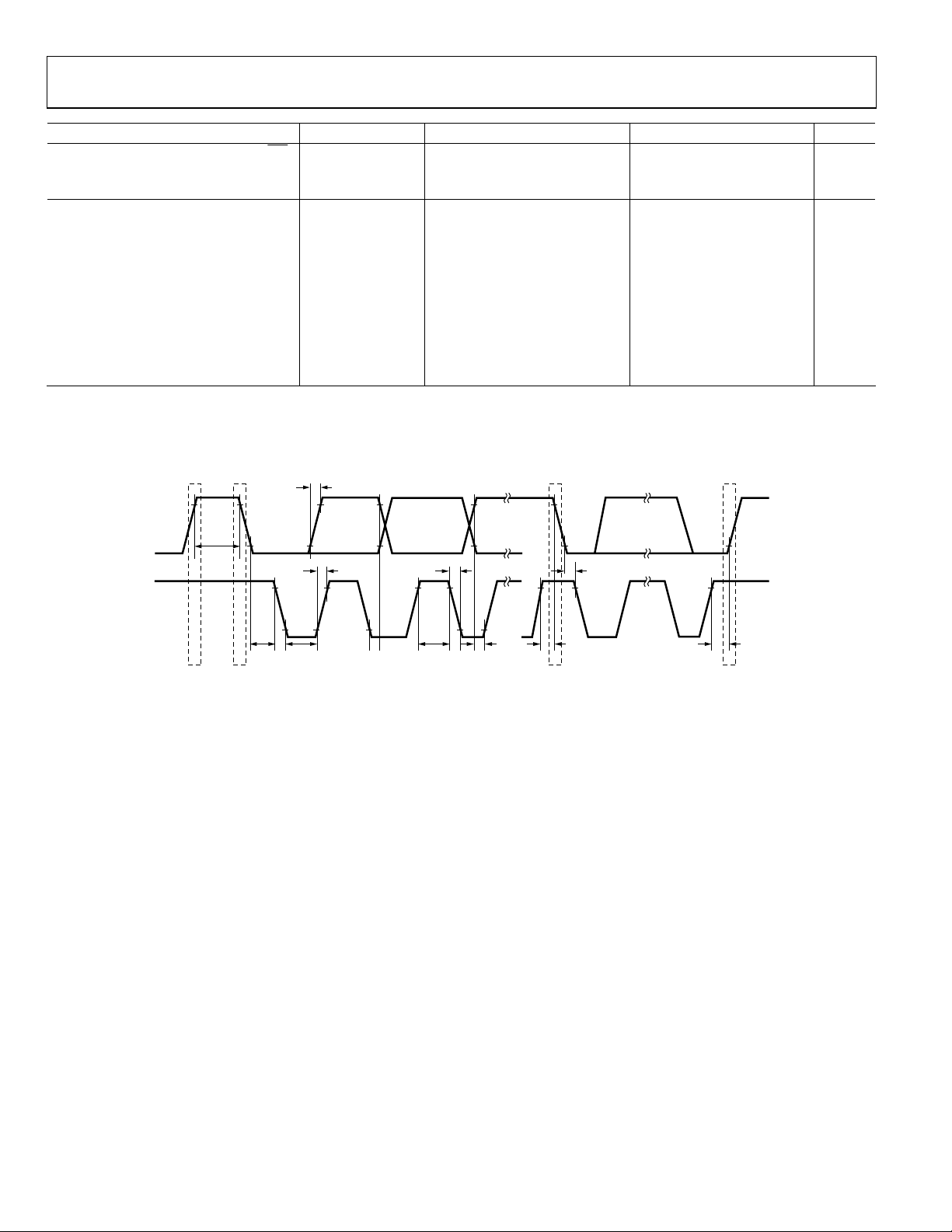
Figure 2. I
t
9
t
4
2
C Timing Diagram
t
5
Rev. 0 | Page 4 of 20
Page 5

AD5255
ELECTRICAL CHARACTERISTICS
Single Supply: VDD = 3 V to 5.5 V and −40°C < TA< +85°C, unless otherwise noted.
Dual Supply: V
Table 2.
Parameter Symbol Conditions Min Typ
DYNAMIC CHARACTERISTICS
Bandwidth −3 dB BW VDD/VSS = ±2.5 V, RAB = 25 kΩ/250 kΩ
Total Harmonic Distortion THD
VW Settling Time t
Resistor Noise Spectral Density e
Digital Crosstalk C
Analog Crosstalk C
INTERFACE TIMING CHARACTERISTICS
(apply to all parts) (Notes
SCL Clock Frequency f
t
Bus Free Time between Stop and
BUF
Start
t
Hold Time (Repeated Start) t
HD;STA
t
Low Period of SCL Clock t
LOW
t
High Period of SCL Clock t
HIGH
t
Setup Time for Start Condition t
SU;STA
t
Data Hold Time t
HD;DAT
t
Data Setup Time t
SU;DAT
tR Rise Time of Both SDA and SCL
Signals
tF Fall Time of Both SDA and SCL
Signals
t
Setup Time for Stop Condition t
SU;STO
EEMEM Data Storing Time t
EEMEM Data Restoring Time at
Power-On
EEMEM Data Restoring Time on
Restore
Command or Reset Operation
EEMEM Data Rewritable Time t
FLASH/EE MEMORY RELIABILITY
Endurance
Data Retention
1
Typical represent average readings at 25°C, VDD = 5 V.
2
Resistor position nonlinearity error R-INL is the deviation from an ideal value measured between the maximum resistance and the minimum resistance wiper
positions. R-DNL measures the relative step change from ideal between successive tap positions.
3
INL and DNL are measured at VW with the RDAC configured as a potentiometer divider similar to a voltage output D/A converter. VA = VDD and VB = 0 V.
4
Resistor Terminals A, B, W have no limitations on polarity with respect to each other.
5
Guaranteed by design and not subject to production test.
6
P
is calculated from (IDD × VDD). CMOS logic level inputs result in minimum power dissipation.
DISS
7
All dynamic characteristics use VDD = 5 V.
8
Bandwidth, noise, and settling time are dependent on the terminal resistance value chosen. The lowest R value results in the fastest settling time and highest
bandwidth. The highest R value results in the minimum overall power consumption.
9
See the timing diagram for location of measured values.
10
Endurance is qualified to 100,000 cycles as per JEDEC Std. 22 method A117 and measured at −40°C, +25°C, and +85°C, typical endurance at 25°C is 700,000 cycles.
11
Retention lifetime equivalent at junction temperature (TJ) = 55°C as per JEDEC Std. 22, Method A117. Retention lifetime based on an activation energy of 0.6eV
derates with junction temperature.
= +2.25 V or +2.75 V , VSS = −2.25 V or −2.75 V and −40°C < TA < + 85°C, unless otherwise noted.
DD
5, 7
W
S
VA = 1 V rms, VB = 0 V, f = 1 kHz
VA = VDD, VB = 0 V,
V
= 0.50% error band,
W
code 0x000 to 0x100, RAB = 25 kΩ/250 kΩ
N_WB
T
RAB = 25 kΩ/250 kΩ, TA = 25°C
VA = VDD, VB = 0 V, measure VW with
adjacent RDAC making full-scale
change
AT
Signal input at A0 and measure output
at W1, f = 1 kHz
8, 9
)
SCL
t
1
2
After this period the first clock pulse is
generated
3
4
5
6
7
t
8
t
9
10
EEMEM_STORE
t
EEMEM_RESTORE1
t
EEMEM_RESTORE2
EEMEM_REWRITE
10
11
55°C
1
Max Unit
125/12 kHz
0.05 %
4/36 µs
14/45 nV√Hz
−80 dB
−72 dB
400 kHz
1.3 µs
600 ns
1.3 µs
0.6 50 µs
600 ns
900 ns
100 ns
300 ns
300 ns
600 ns
26 ms
360 µs
360 µs
540 µs
100
kcycles
100 years
Rev. 0 | Page 5 of 20
Page 6

AD5255
ABSOLUTE MAXIMUM RATINGS
TA = 25°C, unless otherwise noted.
Table 3.
Parameter Rating
VDD to GND −0.3 V, +7 V
VSS to GND +0.3 V, −7 V
VDD to V
SS
VA, VB, VW to GND
IA, IB, I
W
Intermittent
1
7 V
VSS − 0.3 V, VDD + 0.3 V
±20 mA
Continuous ±2 mA
Digital Inputs and Output Voltage to GND −0.3 V, VDD + 0.3 V
Operating Temperature Range
2
−40°C to +85°C
Maximum Junction Temperature (TJ max) 150°C
Storage Temperature −65°C to +150°C
Lead Temperature, Soldering
Vapor Phase (60 sec) 215°C
Infrared (15 sec) 220°C
Thermal Resistance Junction-to-Ambient
, TSSOP-24
θ
JA
_______________________ ________________________________
1
Includes programming of nonvolatile memory.
2
Maximum terminal current is bounded by the maximum current handling of
the switches, maximum power dissipation of the package, and maximum
applied voltage across any two of the A, B, and W terminals at a given
resistance.
143°C/W
Stresses greater than those listed under Absolute Maximum
Ratings may cause permanent damage to the device. This is a
stress rating only and functional operation of the device at these
or any other conditions above those indicated in the operational
section of this specification is not implied. Exposure to absolute
maximum rating conditions for extended periods may affect
device reliability.
ESD CAUTION
ESD (electrostatic discharge) sensitive device. Electrostatic charges as high as 4000 V readily accumulate on
the human body and test equipment and can discharge without detection. Although this product features
proprietary ESD protection circuitry, permanent damage may occur on devices subjected to high energy
electrostatic discharges. Therefore, proper ESD precautions are recommended to avoid performance
degradation or loss of functionality.
Rev. 0 | Page 6 of 20
Page 7

AD5255
PIN CONFIGURATION AND FUNCTION DESCRIPTIONS
A0_EE
A1_RDAC
A0_RDAC
WP
SCL
SDA
DGND
, AV
V
SS
W2
1
2
3
4
RS
5
(Not to Scale)
6
7
8
9
SS
10
A2
11
12
B2
NC = NO CONNECT
AD5255
TOP VIEW
24
A1_EE
23
TEST0 (NC)
22
TEST1 (NC)
21
TEST2 (NC)
20
TEST3 (NC)
19
C
18
A0
17
W0
16
B0
15
B1
14
W1
13
A1
, AV
DD
DD
04555-0-034
Figure 3. Pin Configuration
Table 4. Pin Function Descriptions
Pin No. Mnemonic Description
1 A1_EE I2C Device Address 1 for EEMEM.
2 A1_RDAC I2C Device Address 1 for RDAC.
3 A0_RDAC I2C Device Address 0 for RDAC.
4
RS Resets the scratchpad register with current contents of the EEMEM register. Factory defaults to midscale before
any programming.
5
WP Write Protect. When active low, WP prevents any changes to the present register contents, except that RESET
and Commands 1 and 8 still refresh the RDAC register from EEMEM.
6 SCL Serial Input Register Clock. Shifts in one bit at a time on the positive clock edges.
7 SDA Serial Data Input. Shifts in one bit at a time on the positive clock edges. The MSB is loaded first.
8 DGND Ground. Logic ground reference.
9 V
SS
Negative Supply. Connect to 0 V for single-supply applications.
10 A2 A terminal of RDAC2.
11 W2 Wiper terminal of RDAC2.
12 B2 B terminal of RDAC2.
13 A1 A terminal of RDAC1.
14 W1 Wiper terminal of RDAC1.
15 B1 B terminal of RDAC1.
16 B0 B terminal of RDAC0.
17 W0 Wiper terminal of RDAC0.
18 A0 A terminal of RDAC0.
19 V
DD
Positive Power Supply.
20 TEST3 Test Pin 3. Do not connect.
21 TEST2 Test Pin 2. Do not connect.
22 TEST1 Test Pin 1. Do not connect.
23 TEST0 Test Pin 0. Do not connect.
24 A0_EE I2C Device Address 0 for EEMEM.
Rev. 0 | Page 7 of 20
Page 8

AD5255
TYPICAL PERFORMANCE CHARACTERISTICS
1.0
TA = –40°C, 25°C, 85°C SUPERIMPOSED
V
= 5V
0.8
DD
0.6
0.4
0.2
0
INL (LSB)
–0.2
–0.4
–0.6
–0.8
–1.0
Figure 4. INL—9-Bit RDAC
1.50
TA = –40°C, 25°C, 85°C SUPERIMPOSED
1.25
V
= 5V
DD
1.00
0.75
0.50
0.25
0
–0.25
DNL (LSB)
–0.50
–0.75
–1.00
–1.25
–1.50
Figure 5. DNL—9-Bit RDAC
1.0
TA = –40°C, 25°C, 85°C SUPERIMPOSED
V
= 5V
0.8
DD
0.6
0.4
0.2
0
–0.2
R-INL (LSB)
–0.4
–0.6
–0.8
–1.0
Figure 6. R-INL—9-Bit RDAC
25619264 1280 320 384 448 512
CODE (DECIMAL)
25619264 1280 320 384 448 512
CODE (DECIMAL)
25619264 1280 320 384 448 512
CODE (DECIMAL)
04555-0-002
04555-0-003
04555-0-004
1.0
0.8
0.6
0.4
0.2
0
–0.2
R-DNL (LSB)
–0.4
–0.6
–0.8
TA = –40°C, 25°C, 85°C SUPERIMPOSED
V
= 5V
DD
–1.0
Figure 7. R-DNL—9-Bit RDAC
0.5
TA = –40°C, 25°C, 85°C SUPERIMPOSED
V
= 5V
0.4
DD
0.3
0.2
0.1
0
INL (LSB)
–0.1
–0.2
–0.3
–0.4
–0.5
Figure 8. INL—7-Bit RDAC
0.5
TA = –40°C, 25°C, 85°C SUPERIMPOSED
V
= 5V
0.4
DD
0.3
0.2
0.1
0
DNL (LSB)
–0.1
–0.2
–0.3
–0.4
–0.5
Figure 9. DNL—7-Bit RDAC
25619264 1280 320 384 448 512
CODE (DECIMAL)
04555-0-005
644816 320809611
CODE (DECIMAL)
2128
04555-0-006
644816 320809611
CODE (DECIMAL)
2128
04555-0-007
Rev. 0 | Page 8 of 20
Page 9

AD5255
0.5
TA = –40°C, 25°C, 85°C SUPERIMPOSED
V
= 5V
0.4
DD
0.3
0.2
0.1
0
–0.1
R-INL (LSB)
–0.2
–0.3
–0.4
–0.5
Figure 10. R-INL—7-Bit RDAC
0.5
TA = –40°C, 25°C, 85°C SUPERIMPOSED
V
= 5V
0.4
DD
0.3
0.2
0.1
0
–0.1
R-DNL (LSB)
–0.2
–0.3
–0.4
–0.5
Figure 11. R-DNL—7-Bit RDAC
50
TA = –40°C, 85°C
V
= 5V
45
DD
VA = V
DD
VB = 0V
40
35
30
25
20
15
10
RHEOSTAT MODE TEMPCO (ppm/°C)
5
0
Figure 12. Temperature Coefficient (Rheostat Mode)
644816 320809611
CODE (DECIMAL)
2128
04555-0-008
644816 320809611
CODE (DECIMAL)
2128
04555-0-009
25619264 1280 320 384 448 512
CODE (DECIMAL)
04555-0-010
50
TA = –40°C, 85°C
V
= 5V
45
DD
V
= V
A
DD
VB = 0V
40
35
30
25
20
15
10
5
POTENTIOMETER MODE TEMPCO (ppm/°C)
0
25619264 1280 320 384 448 512
CODE (DECIMAL)
Figure 13. Temperature Coefficient (Potentiometer Mode)
10
8
IDD: VDD = 5.5V
6
4
2
I
: VDD = 2.7V
DD
0
–2
I
: VDD = 2.7V, VSS = 2.7V
S
–4
SUPPLY CURRENT (mA)
–6
–8
–10
–40 –20 0 20 40 60 80 100 120 140
TEMPERATURE (°C)
Figure 14. Supply Current vs. Temperature
110
TA = 25°C
100
90
80
70
(mA)
DD
I
60
V
= 5.5V
50
40
30
110
1
DD
V
= 2.7V
DD
10210310410510610
CLOCK FREQUENCY (Hz)
Figure 15. Supply Current vs. Clock Frequency
04555-0-011
04555-0-012
7
04555-0-013
Rev. 0 | Page 9 of 20
Page 10

AD5255
INTERFACE DESCRIPTIONS
I2C INTERFACE
All control and access to both EEPROM memory and the RDAC
registers are conducted via a standard 2-wire I
Figure 2 shows the timing characteristics of the I
Figure 16 and Figure 17 illustrate standard transmit and receive
2
bus signals in the I
C interface.
These figures use the following legend:
From master to slave
From slave to master
S = Start condition
P = Stop condition
A = Acknowledge (SDA low)
= Not acknowledge (SDA high)
A
2
C interface.
2
C bus.
= Read enable at high and write enable at low
R/
W
SLAVE ADDRESSS
SLAVE ADDRESSS
SLAVE ADDRESSS
R/W SLAVE ADDRESSS
READ OR WRITE
R/W
0 = WRITE
R/W
1 = WRITE
A DATA
(N BYTES + ACKNOWLEDGE)
A DATA A
DATA TRANSFERRED
(N BYTES + ACKNOWLEDGE)
2
Figure 16. I
C—Master Transmitting Data to Slave
A DATA A
DATA TRANSFERRED
(N BYTES + ACKNOWLEDGE
2
Figure 17. I
C—Master Reading Data from Slave
A/A P
REPEATED START
Figure 18. Combined Transmit/Read
R/W
READ OR WRITE
DATA A/A P
DATA A
A DATA
(N BYTES + ACKNOWLEDGE)
DIRECTION OF TRANSFER MAY
CHANGE AT THIS POINT
A/A
P
04555-0-016
04555-0-017
04555-0-018
Rev. 0 | Page 10 of 20
Page 11

AD5255
EEPROM INTERFACE
0011
01
EE
MEMORY ADDRESS MEMORY DATA MEMORY DATASAAAAA00
A/A
P
0 WRITE
Figure 19. EEPROM Write
0011
SLAVE ADDRESS MEMORY ADDRESSS
0 WRITE
01
EE
1 READ
AA P
W SLAVE ADDRESS MEMORY DATASR
MEMORY DATA MEMORY DATASAAAA00
Figure 20. EEPROM Current Read
Figure 21. EEPROM Random Read
The 256 bytes of EEPROM memory provided in the AD5255
are organized into 16 pages of 16 bytes each. The word size of
each memory location is one byte wide.
2
C slave address of the EEPROM is 10100(A1E)(A0E),
The I
where A1E and A0E are external pin-programmable address
bits. The 2-pin programmable address bits allow a total of four
2
AD5255 devices to be controlled by a single I
C master bus,
each having its own EEPROM.
An internal 8-bit address counter for the EEPROM is
automatically incremented following each read or write
operation. For read operations, the address counter is
incremented after each byte is read, and the counter rolls over
from Address 255 to 0.
For write operations, the address counter is incremented after
each byte is written. The counter rolls over from the highest
address of the current page to the lowest address of the current
page. For example, writing two bytes beginning at Address 31
causes the counter to roll back to Address 16 after the first byte
is written; then the address increments to 17 after the second
byte is written.
EEPROM Write
Each write operation issued to the EEPROM programs between
1 byte and 16 bytes (1 page) of memory. Figure 19 shows the
EEPROM write interface. The number of bytes of data, N, that
the user wants to send to the EEPROM is unrestricted. If more
REPEATED START
than 16 bytes of data are sent in a single write operation, the
address counter rolls back to the beginning address, and the
previously sent data is overwritten.
EEPROM Write-Acknowledge Polling
After each write operation, an internal EEPROM write cycle
begins. During the EEPROM internal write cycle, the I
interface of the device is disabled. It is necessary to determine if
the internal write cycle is complete and whether the I
interface is enabled. To do so, execute I
sending a start condition followed by the EEPROM slave
address plus the desired R/
responds with an ACK, the write cycle is complete and the
interface is ready to proceed with further operations. Otherwise,
the I
write cycle has been completed.
EEPROM Read
The AD5255 EEPROM provides two different read operations,
shown in Figure 20 and Figure 21. The number of bytes, N, read
from the EEPROM in a single operation is unrestricted. If more
than 256 bytes are read, the address counter rolls back to the
start address, and data previously read is read again.
Figure 20 shows the EEPROM current read operation. This
operation does not allow an address location to be specified,
and reads data beginning at the current address location stored
in the internal address counter.
(N BYTES + ACKNOWLEDGE)EEPROM SLAVE ADDRESS
A
(N BYTES + ACKNOWLEDGE)EEPROM SLAVE ADDRESS
A
1 READ
2
C interface must be polled again to determine whether the
(N BYTES + ACKNOWLEDGE)
2
C interface polling by
bit. If the AD5255 I2C interface
W
A/A
2
C
2
C
04555-0-019
P
04555-0-020
04555-0-021
Rev. 0 | Page 11 of 20
Page 12

AD5255
A random read operation is shown in Figure 21. This operation
changes the address counter to the specified memory address by
performing a dummy write and then performing a read
operation beginning at the new address counter location.
RDAC I2C INTERFACE
EEPROM Write Protection
Setting the WP pin to a logic low protects the EEPROM
memory from future write operations. In this mode, EEPROM
read operations and RDAC register loading operate normally.
1100
01
R
R
0 WRITE
SAAA11
1100
01
R
R
1 READ
SLAVE ADDRESS RDAC ADDRESSS
0 WRITE
AA P
W SLAVE ADDRESS RDAC DATASR
CMD/
REG
EE/RDA4A3A2A1A
AC
Figure 22. RDAC Write
Figure 23. RDAC Current Read
REPEATED START
Figure 24. RDAC Random Read
0
ARDAC EEPROM OR REGISTER DATA RDAC EEPROM OR REGISTER DATA
(N BYTES + ACKNOWLEDGE)RDAC SLAVE ADDRESS
1 READ
DATA DATASA AAAA10 0
(N BYTES + ACKNOWLEDGE)RDAC ADDRESSRDAC SLAVE ADDRESS
A
(N BYTES + ACKNOWLEDGE)
A/A
A/A
P
04555-0-022
P
A
04555-0-023
04555-0-024
SAAA10
1100
RDAC SLAVE ADDRESS
01
R
R
0 WRITE
CMD/
REG
1 CMD
C
2
3
C0A2A1A
1
0
C
C
Figure 25. RDAC Shortcut Command
Table 5. RDAC Register Addresses (CMD/
REG
= 0, EE/
RDAC
= 0)
A4 A3 A2 A1 A0 RDAC Byte Description
0 0 0 0 0 RDAC0 (D7)(D6)(D5)(D4)(D3)(D2)(D1)(D0) – RDAC0 8 LSBs
0 0 0 0 1 RDAC0 (X)(X)(X)(X)(X)(X)(X)(D8) – RDAC0 MSB
0 0 0 1 0 RDAC1 (D7)(D6)(D5)(D4)(D3)(D2)(D1)(D0) – RDAC1 8 LSBs
0 0 0 1 1 RDAC1 (X)(X)(X)(X)(X)(X)(X)(D8) – RDAC1 MSB
0 0 1 0 0 RDAC2 (X)(D6)(D5)(D4)(D3)(D2)(D1)(D0) – RDAC2 7 bits
0 0 1 0 1 Reserved
…to…
1 1 1 1 1
Rev. 0 | Page 12 of 20
P
A
04555-0-025
Page 13

AD5255
Table 6. RDAC R/W EEPROM Addresses (CMD/
A4 A3 A2 A1 A0 Byte Description
0 0 0 0 0 RDAC0 8 LSBs
0 0 0 0 1 RDAC0 MSB
0 0 0 1 0 RDAC1 8 LSBs
0 0 0 1 1 RDAC1 MSB
0 0 1 0 0 RDAC2 7 bits
0 0 1 0 1 11 bytes RDAC User EEPROM
…to…
0 1 1 1 1
Table 7. RDAC Command Table (CMD/
C3 C2 C1 C0 Command Description
0 0 0 0 NOP
0 0 0 1 Restore EEPROM to RDAC
0 0 1 0 Store RDAC to EEPROM
0 0 1 1 Decrement RDAC 6 dB
0 1 0 0 Decrement All RDACs 6 dB
0 1 0 1 Decrement RDAC 1 Step
0 1 1 0 Decrement All RDACs 1 Step
0 1 1 1 Reset. Restore EEPROM to all RDACs2
1 0 0 0 Increment RDACs 6 dB
1 0 0 1 Increment All RDACs 6 dB
1 0 1 0 Increment RDAC 1 Step
1 0 1 1 Increment All RDAC 1 Step
1 1 0 0 Reserved
…to…
1 1 1 1
REG
= 1)
1
Command leaves the device in the EEPROM read power state. Issue the NOP command to return the device to the idle state.
2
Command requires acknowledge polling after execution.
RDAC Interface Operation
Each programmable resistor wiper setting is controlled by
specific RDAC registers, as shown in Table 5. Each RDAC
register corresponds to an EEPROM memory location, which
provides nonvolatile wiper storage functionality.
RDAC registers and their corresponding EEPROM memory
locations are programmed and read independently from each
other. The RDAC register is refreshed by the EEPROM locations
either with a hardware reset via Pin 1, or by issuing one of the
various RDAC register load commands shown in the Table 7.
RDAC Write
Setting the wiper position requires an RDAC write operation,
shown in Figure 22. RDAC write operations follow a format
similar to the EEPROM write interface. The only difference
between an RDAC write and an EEPROM write operation is the
use of an RDAC address byte in place of the memory address
used in the EEPROM write operation. The RDAC address byte
is described in detail in Table 5 and Table 6.
REG
= 0, EE/
RDAC
= 1)
1
2
As with the EEPROM write operation, any RDAC EEPROM
2
(Shortcut Command 2) write operation disables the I
C
interface during the internal write cycle. Acknowledge polling,
as described in the EEPROM Interface section, is required to
determine whether the write cycle is complete.
RDAC Read
The AD5255 provides two RDAC read operations. The first,
shown in Figure 23, reads the contents of the current RDAC
address counter. Figure 24 illustrates the second read operation,
which allows users to specify which RDAC register to read by
first issuing a “dummy write” command to change the RDAC
address pointer, and then proceeding with the RDAC read
operation at the new address location.
The read-only RDAC EEPROM memory locations can also be
read by using the address and bits specified in Table 6.
Rev. 0 | Page 13 of 20
Page 14

AD5255
RDAC Shortcut Commands
Eleven “shortcut” commands are provided for easy manipulation
of RDAC registers and their corresponding EEPROM memory
locations. These commands are shown in Table 9. A more detailed
discussion about the RDAC shortcut commands can be found
in the Theory of Operation section.
The interface for issuing an RDAC shortcut command is shown
in Figure 25. All shortcut commands require acknowledge
polling to determine whether the command has finished
executing.
RDAC Resistor Tolerance
The end-to-end resistance tolerance for each RDAC channel is
stored in read-only memory during factory production. This
information is read by using the address and bits specified in
Tabl e 8.
Tolerance values are stored in percentage form. Figure 26 shows
the format of the tolerance data stored in memory. Each stored
tolerance uses two memory locations. The first location stores
the integer portion, while the second location stores the decimal
portion.
The resistance tolerance is stored in sign-magnitude format.
The MSB of the first memory location designates the sign
(0 = +, 1 = −) and the remaining 7 LSBs are designated for the
integer portion of the tolerance. All 8 bits of the second
memory location are represented the decimal portion of the
tolerance value.
Table 8. Addresses for Reading Tolerance (CMD/
REG
= 0, EE/
RDAC
= 1, A4 = 1)
A4 A3 A2 A1 A0 Data Byte Description
1 1 0 0 0 Sign and 7-Bit Integer Values of RDAC0 Tolerance (Read-Only)
1 1 0 0 1 8-Bit Decimal Value of RDAC0 Tolerance (Read-Only)
1 1 0 1 0 Sign and 7-Bit Integer Values of RDAC1 Tolerance (Read-Only)
1 1 0 1 1 8-Bit Decimal Value of RDAC1 Tolerance (Read-Only)
1 1 1 0 0 Sign and 7-Bit Integer Values of RDAC2 Tolerance (Read-Only)
1 1 1 0 1 8-Bit Decimal Value of RDAC2 Tolerance (Read-Only)
A AD6 D5 D4 D3 D2 D1 D0D7
6
5
4
3
2
1
SIGN 2
2
2
2
2
2
7 BITS FOR INTEGER NUMBERSIGN
0
2
2
Figure 26. Format of Stored Tolerance in Sign Magnitude with Bit Positions Descriptions Unit is in %. Only Data Bytes Shown.
–2
–1
2
–3
–4
2
2
8 BITS FOR DECIMAL NUMBER
AD6 D5 D4 D3 D2 D1 D0D7
–5
–6
–7
2
2
2
–8
2
04555-0-026
Rev. 0 | Page 14 of 20
Page 15

AD5255
THEORY OF OPERATION
The AD5255 digital potentiometer operates as a true variable
resistor. The RDAC register contents determine the resistor
wiper position. The RDAC register acts like a scratch-pad
register, allowing unlimited resistance setting changes. RDAC
2
register contents are changed using the AD5255’s serial I
C
interface. See the RDAC I2C Interface section for the format of
the data words and commands to program the RDAC registers.
Each RDAC register has a corresponding EEPROM memory
location, which provides nonvolatile storage of resistor wiper
position settings. The AD5255 provides commands to store the
RDAC register contents to their respective EEPROM memory
locations. During subsequent power-on sequences, the RDAC
registers are automatically loaded with the stored values.
Saving data from an RDAC register to EEPROM memory takes
approximately 25 ms and consumes 35 mA.
In addition to moving data between RDAC registers and
EEPROM memory, the AD5255 provides other shortcut
commands.
Table 9. AD5255 Shortcut Commands
No. Function
1 Restore EEPROM setting to RDAC
2. Store RDAC register contents to EEPROM
3 Decrement RDAC 6 dB (shift data bits right)
4 Decrement all RDACs 6 dB (shift all data bits right)
5 Decrement RDAC 1 step
6 Decrement all RDACs 1 step
7 Reset EEPROM setting to RDAC
8 Increment RDAC 6 dB (shift data bits left)
9 Increment all RDACs 6 dB (shift all data bits left)
10 Increment RDAC 1 step
11 Increment all RDACs 1 step
__________________________
1
Command leaves the device in the EEPROM read power state. Issue the NOP
command to return the device to the idle state.
2
Command requires acknowledge polling after execution.
1
2
2
LINEAR INCREMENT AND DECREMENT COMMANDS
The increment and decrement commands (Commands 10, 11,
5, and 6) are useful for linear step adjustment applications.
These commands simplify microcontroller software coding by
allowing the controller to send only an increment or decrement
command to the AD5255. The adjustment can be directed to an
individual RDAC or to all three RDACs.
LOGARITHMIC TAPER MODE ADJUSTMENT
(±6 dB/STEP)
The AD5255 accommodates logarithmic taper adjustment of
the RDAC wiper position(s) by shifting the register contents
left/right for increment/decrement operations. Commands 8, 9,
3, and 4 are used to logarithmically increment or decrement the
wiper positions individually or change all three channel settings
at the same time.
Incrementing the wiper position by +6 dB doubles the RDAC
register value, while decrementing by −6 dB halves it. Internally,
the AD5255 uses a shift register to shift the bits left and right to
achieve a logarithmic increment or decrement.
Nonideal ±6 dB step adjustment occurs under certain conditions.
Table 10 illustrates how the shifting function affects the data
bits of an individual RDAC. Each line going down the table
represents a successive shift operation. Note that the left-shift
commands (Commands 10 and 11) were modified such that if
the data in the RDAC register equals 0 and the data is shifted,
the RDAC register is set to Code 1. Similarly, if the data in the
RDAC register is greater than or equal to midscale and the data
is left shifted, the data in the RDAC register is automatically set
to full-scale. This makes the left-shift function as close as possible
to a logarithmic adjustment.
The right-shift commands (Commands 3 and 4) are ideal only
if the LSB is a 0 (ideal logarithmic = no error). If the LSB is 1,
the right-shift function generates a linear half LSB error.
Table 10. RDAC Register Contents after
±6 dB Step Adjustments
Left Shift (+6 dB/step) Right Shift (−6 dB/step)
0 0000 0000 1 1111 1111
0 0000 0001 0 1111 1111
0 0000 0010 0 0111 1111
0 0000 0100 0 0011 1111
0 0000 1000 0 0001 1111
0 0001 0000 0 0000 1111
0 0010 0000 0 0000 0111
0 0100 0000 0 0000 0011
0 1000 0000 0 0000 0001
1 0000 0000 0 0000 0000
1 1111 1111 0 0000 0000
1 1111 1111
Actual conformance to a logarithmic curve between the data
contents in the RDAC register and the wiper position for each
right-shift command (Commands 3 and 4) execution contains
an error only for odd numbers of bits. Even numbers of bits are
ideal. Figure 26 shows a plot of Log_Error, that is, 20 ×
Log10(error/code), for the AD5255.
Rev. 0 | Page 15 of 20
Page 16

AD5255
V
USING ADDITIONAL INTERNAL NONVOLATILE EEPROM
The AD5255 contains additional internal user EEPROM for
saving constants and other data. The user EEPROM I
word follows the same format as the general-purpose EEPROM
memory shown in Figure 19 and Figure 20. User EEPROM
memory addresses are shown in Table 6.
To support the use of multiple EEPROM modules on a single
2
I
C bus, the AD5255 features two external addressing pins, Pins
21 and 22 (A1_EE and A0_EE) to manually set the address of
the EEPROM included with the AD5255. This feature ensures
that the correct EEPROM memory is accessed when using
2
multiple memory modules on a single I
C bus.
DIGITAL INPUT/OUTPUT CONFIGURATION
All digital inputs are ESD protected. Digital inputs are high
impedance and can be driven directly from most digital sources.
The
resistor. Therefore, the user should place a pull-up resistor from
RESET
internal pull-down resistor. If not driven by an external source,
the AD5255 defaults to a write-protected state. ESD protection
of the digital inputs is shown in Figure 27.
digital input pin does not have an internal pull-up
RESET
to VDD if the function is not used. The WP pin has an
V
DD
2
C data
LEVEL SHIFT FOR BIDIRECTIONAL COMMUNICATION
While most legacy systems operate at one voltage, adding a new
component might require a different voltage. When two systems
transmit the same signal at two different voltages, use a level
shifter to allow the systems to communicate.
For example, a 3.3 V microcontroller (MCU) can be used along
with a 5 V digital potentiometer. A level shifter is required to
enable bidirectional communication.
Figure 29 shows one of many possible techniques to properly
level-shift signals between two devices. M1 and M2 are
N-channel FETs (2N7002). If V
threshold N-channel FETs (FDV301N) for M1 and M2.
= 3.3V V
DD1
R
SDA1
SCL1
3.3V
MCU
Figure 29. Level Shifting for Different Voltage Devices on an I
R
P
P
S
falls below 2.5 V, use low
DD
R
P
G
D
G
M1
D
S
M2
R
P
5V
AD5255
DD2
2
C Bus
= 5V
SDA2
SCL2
04555-0-029
INPUTS
WP
GND
Figure 27. Equivalent
WP
ESD Protection
04555-0-027
MULTIPLE DEVICES ON ONE BUS
Figure 28 shows four AD5255 devices on the same serial bus.
Each has a different slave address since the state of their AD0
and AD1 pins are different. This allows independent reading
and writing to each RDAC within each device.
+5V
R
R
P
P
MASTER
SDA
SCL SDA
AD1
AD0
V
DD
AD1
AD0
V
DD
SCL SDA
AD1
AD0
V
DD
SCL SDA
AD1
AD0
Figure 28. Multiple AD5255 Devices on a Single Bus
SDA
SCL
SCL
04555-0-028
TERMINAL VOLTAGE OPERATION RANGE
The AD5255 positive VDD and negative VSS power supply inputs
define the boundary conditions for proper 2-terminal
programmable resistance operation. Supply signals on terminals
W and B that exceed V
forward-biased diodes of the AD5255.
Figure 30. Maximum Terminal Voltages Set by V
The ground pin of the AD5255 is used as a digital ground
reference, and needs to be tied to the common ground of the
PCB. Reference the digital input control signals to the AD5255
ground pin, and satisfy the logic levels defined in the
Specifications tables.
or VSS are clamped by the internal
DD
V
DD
A
W
B
V
SS
04555-0-030
and V
DD
SS
Rev. 0 | Page 16 of 20
Page 17

AD5255
POWER-UP SEQUENCE
Since the ESD protection diodes limit the voltage compliance at
the A, B, and W terminals (Figure 30), it is important to power
before applying any voltage to the A, B, and W
V
DD/VSS
terminals. Otherwise, the diode is forward-biased such that
are powered unintentionally, which affects the rest of
V
DD/VSS
the circuit. The ideal power-up sequence is as follows: GND,
, VSS, digital inputs, and V
V
DD
, VW, and the digital inputs is not important as long as they
V
B
are powered after V
DD/VSS
. The order of powering VA,
A/B/W
.
Since the switches are nonideal, there is a 100 Ω wiper
resistance, R
. Wiper resistance is a function of supply voltage
W
and temperature; lower supply voltages and higher temperatures
result in higher wiper resistances. Consideration of wiper
resistance dynamics is important in applications in which
accurate prediction of output resistance is required.
SW
A
A
X
N
–1)
SW(2
LAYOUT AND POWER SUPPLY BIASING
It is always a good practice to use compact, minimum lead
length layout design. Make the leads to the input as direct as
possible with a minimum conductor length. Make sure that
ground paths have low resistance and low inductance.
Similarly, it is also good practice to bypass the power supplies
with quality capacitors. Use low equivalent series resistance
(ESR) 1 µF to 10 µF tantalum or electrolytic capacitors at the
supplies to minimize any transient disturbance and filter low
frequency ripple. Figure 31 illustrates the basic supplybypassing configuration for the AD5255.
AD5255
V
DD
+
C3
10µF
+
C4
10µF
V
SS
C1
0.1µF
C2
0.1µF
Figure 31. Power Supply Bypassing
V
DD
GND
V
SS
04555-0-031
RDAC STRUCTURE
The patent pending RDAC contains a string of equal resistor
segments, with an array of analog switches. The switches act as
the wiper connection.
The AD5255 has two RDACs with 512 connection points
allowing it to provide better than 0.2% set-ability resolution.
The AD5255 also contains a third RDAC with 128-step
resolution.
Figure 32 shows an equivalent structure of the connections
between the two terminals that make up one channel of an
RDAC. The SW
SW(0) to SW(2
depending on the resistance position decoded from the data bits
in the RDAC register.
switch is always on, while one of the switches,
B
N
− 1), may or may not be on at any given time
RDAC
WIPER
REGISTER
AND
DECODER
= RAB/2
R
S
DIGITAL
CIRCUITRY
OMITTED FOR
CLARITY
R
S
N
SW(2
R
S
SW(1)
R
S
N
SW(0)
SW
W
–2)
B
X
B
X
04555-0-032
Figure 32. Equivalent RDAC Structure
CALCULATING THE PROGRAMMABLE RESISTANCE
The nominal resistance of the RDAC between the A and B
terminals is available in 25 kΩ or 250 kΩ. The final two or three
digits of the part number determine the nominal resistance
value, for example, 25 kΩ = 25 and 250 kΩ = 250.
The following discussion describes the calculation of resistance
(d) at different codes of a 25 kΩ part for RDAC0. The 9-bit
R
WB
data word in the RDAC latch is decoded to select one of the 512
possible settings.
The first wiper connection starts at the B terminal for data 0x000.
(0) is 100 Ω of the wiper resistance and it is independent of
R
WB
the full-scale resistance. The second connection is the first tap
point where R
0x001. The third connection is the next tap point representing
(2) = 97.6 + 100 = 197.6 Ω for data 0x002, and so on. Each
R
WB
LSB data-value increase moves the wiper up the resistor ladder
until the last tap point is reached at R
Figure 32 for a simplified diagram of the equivalent RDAC
circuit.
These general equations determine the programmed output
resistance between W and B.
(1) becomes 48.8 Ω + 100 = 148.8 Ω for data
WB
(511) = 25051 Ω. See
WB
Rev. 0 | Page 17 of 20
Page 18

AD5255
For RDAC0 and RDAC1:
WB
512
AB
D
()
DR +×=
For RDAC2:
WB
128
AB
D
()
DR +×=
where D is the decimal equivalent of the data contained in the
RDAC register and R
is the wiper resistance.
W
The output resistance values in Table 11 are set for the given
RDAC latch codes with V
digital potentiometers.
Table 11. R
at Selected Codes for R
WB
D (DEC) RWB(d) (Ω) Output State
511 25051 Full scale
256 12600 Midscale
1 148.8 1 LSB
0 100 Zero scale (wiper contact resistance)
Note that in the zero-scale condition, a finite wiper resistance of
100 Ω is present. To avoid degradation or possible destruction
of the internal switches, care should be taken to limit the current
flow between W and B to no more than 20 mA intermittently or
2 mA continuously.
Channel-to-channel R
change in R
with temperature has a 35 ppm/°C temperature
WB
WB
coefficient.
Like the mechanical potentiometer that the RDAC replaces, the
AD5255 parts are totally symmetrical. The resistance between
the W wiper and the A terminal also produces a digitally
controlled complementary resistance, R
the B terminal can be floating or tied to the wiper. Setting the
resistance value for R
starts at a maximum value of resistance
WA
and decreases as the data loaded in the latch is increased in
value. The general transfer equations for this operation are as
follows.
For RDAC0 and RDAC1:
WB
512
D
−
512
()
DR +×
=
For RDAC2:
128
D
()
DR +×
WB
−
=
128
(1)
RR
W
(2)
RR
W
= 5 V, which applies to RAB = 25 kΩ
DD
= 25 kΩ
WB_FS
matching is better than 0.1%. The
. When RWA is used,
WA
(3)
RR
W
AB
(4)
RR
W
AB
For example, the following RDAC latch codes set the
corresponding output resistance values, which apply to
R
= 25 kΩ digital potentiometers.
AB
Table 12. R
(d) at Selected Codes for RAB = 25 kΩ
WA
D (DEC) RWA(d) (Ω) Output State
511 148.8 Full scale
256 12600 Midscale
1 25051 1 LSB
0 25100 Zero scale
The typical distribution of RAB from channel-to-channel is
±0.1% within the same package. Device-to-device matching is
process lot-dependent, with a worst-case variation of ±15%. R
AB
temperature coefficient is 35 ppm/°C.
PROGRAMMING THE POTENTIOMETER DIVIDER
Voltage Output Operation
The digital potentiometer can be configured to generate an
output voltage at the wiper terminal that is proportional to the
input voltages applied to the A and B terminals. Connecting the
A terminal to 5 V and the B terminal to ground produces an
output voltage at the wiper that can vary between 0 V to 5 V.
Each LSB of voltage is equal to the voltage applied across the A
and B terminals divided by the 2
potentiometer divider.
Since the AD5255 can operate from dual supplies, the general
equations defining the output voltage at V
ground for any given input voltages applied to the A and B
terminals are as follows.
For RDAC0 and RDAC1:
W
512
AB
D
()
DV +×=
For RDAC2:
W
128
AB
D
()
DV +×=
Equation 5 assumes that V
wiper resistance is nulled. Operation of the digital potentiometer
in the divider mode results in more accurate operation over
temperature. In this mode, the output voltage is dependent on
the ratio of the internal resistors, not on the absolute value;
therefore, the drift improves to 15 ppm/°C. There is no voltage
polarity restriction between the A, B, and W terminals as long as
the terminal voltage (V
TERM
N
position resolution of the
with respect to
W
(5)
VV
B
(6)
VV
B
is buffered so that the effect of
W
) stays within VSS < V
TERM
< VDD.
Rev. 0 | Page 18 of 20
Page 19

AD5255
APPLICATIONS
LASER DIODE DRIVER (LDD) CALIBRATION
The AD5255 can be used with any laser diode driver. Its high
resolution, compact footprint, and superior temperature drift
characteristics make it ideal for optical parameter setting.
The ADN2841 is a 2.7 Gbps laser diode driver that uses a
unique control algorithm to manage both the laser average
power and extinction ratio after initial factory calibration. It
stabilizes the laser data transmission by continuously
monitoring its optical power and by correcting the variations
caused by temperature and the laser degradation over time. In
the ADN2841, the I
Through its dual-loop power and extinction ratio control,
calibrated by the AD5255, the internal driver controls the bias
current I
and consequently the average power. It also
BIAS
regulates the modulation current, I
modulation current linearly with slope efficiency. Any changes
monitors the laser diode current.
MPD
, by changing the
MODP
in the laser threshold current or slope efficiency are, therefore,
compensated. As a result, this optical supervisory system
minimizes the laser characterization efforts, enabling designers
to apply comparable lasers from multiple sources.
V
V
CC
CC
AD5255
SDA
SCL
Figure 33. Optical Supervisory System
PSET
ERSET
ASET
ADN2841
04555-0-033
Rev. 0 | Page 19 of 20
Page 20

AD5255
OUTLINE DIMENSIONS
7.90
7.80
7.70
24
PIN 1
0.15
0.05
0.10 COPLANARITY
0.65
BSC
0.30
0.19
COMPLIANT TO JEDEC STANDARDS MO-153AD
13
121
1.20
MAX
SEATING
PLANE
4.50
4.40
4.30
6.40 BSC
0.20
0.09
8°
0°
0.75
0.60
0.45
Figure 34. 24-Lead Thin Shrink Small Outline Package [TSSOP]
(RU-24)
Dimensions shown in millimeters
ORDERING GUIDE
Temperature
Model
Range Package Description Package Option
AD5255BRU25 −40°C to +85°C Thin Shrink Small Outline Package RU-24 62 25
AD5255BRU25-RL7 −40°C to +85°C Thin Shrink Small Outline Package RU-24 1,000 25
AD5255BRU250 −40°C to +85°C Thin Shrink Small Outline Package RU-24 62 250
AD5255BRU250-RL7 −40°C to +85°C Thin Shrink Small Outline Package RU-24 1,000 250
Purchase of licensed I
Rights to use these components in an I
2
C components of Analog Devices or one of its sublicensed Associated Companies conveys a license for the purchaser under the Philips I2C Patent
2
C system, provided that the system conforms to the I2C Standard Specification as defined by Philips.
Full Container
Quantity RAB (kΩ)
© 2004 Analog Devices, Inc. All rights reserved. Trademarks and
registered trademarks are the property of their respective owners.
D04555–0–7/04(0)
Rev. 0 | Page 20 of 20
 Loading...