

Page 1
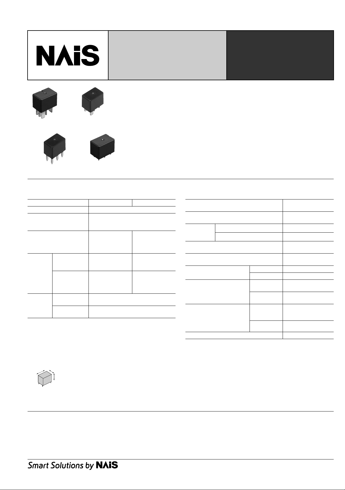
AUTOMOTIVE LOW PROFILE
MICRO-ISO/MICRO-280
RELAY
FEATURES
• Low profile:
22.5 mm(L)×15 mm(W)×15.7 mm(H)
.886 inch(L)×.591 inch(W)×.618 inch(H)
• Low temperature rise
Micro ISO 1c type Micro ISO 1a type
Terminal temperature has been reduced
compared with using our conventional
product
• Low sound pressure level
Noise level has been reduced
approx.10dB compared with using our
conventional product.
Micro 280 plug-in type Micro 280 PCB type
SPECIFICATIONS
Contact
Arrangement 1 Form A 1 Form C
Contact material Silver alloy
Initial contact resistance,
max. (By voltage drop 6 V
DC 1 A)
Initial contact voltage drop,
max.
Nominal
switching
capacity
Rating
Expected
life (min.
operation)
Remarks
* Specifications will vary with foreign standards certification ratings.
*1At nominal switching capacity, operating frequency: 2s ON, 2s OFF
2
Measurement at same location as “Initial breakdown voltage” section.
*
*3Detection current: 10mA
*4Excluding contact bounce time.
5
Half-wave pulse of sine wave: 11 ms; detection time: 10 µs
*
*6Half-wave pulse of sine wave: 6 ms
7
Detection time: 10 µs
*
*8Time of vibration for each direction;
X
Max. carrying
current
(14 V DC,
at 85°C 185°F)
Mechanical
(at 120 cpm)
Electrical
(at rated load)
X, Y, Z direction: 4 hours
Y
Z
N.O.: 0.2 V
(at 20 A switching)
N.O.: 20 A 14 V DC
N.O.: 20 A
50m
Ω
N.O.: 0.2 V
(at 20 A switching)
N.C.: 0.5 V
(at 10 A switching)
N.O.: 20 A 14 V DC
N.C.: 10 A 14 V DC
N.O.: 20 A
N.C.: 10 A
6
Min. 10
Min. 105*
1
CV
CV-RELAYS
• Wide line-up
Micro ISO/Micro 280 terminal types and
resistor and diode inside type, PCB
terminal type (Micro 280 only).
• Plastic sealed type
Plastically sealed for automatic cleaning.
Characteristics
Max. operating speed
(at nominal switching capacity)
Initial insulation resistance *
Initial
breakdown
voltage *
Operate time *
(at nominal voltage) (at 20°C 68°F)
Release time (without diode) *
(at nominal voltage) (at 20°C 68°F)
Shock resistance
Vibration resistance
Conditions in case of
operation, transport and
storage *
(Not freezing and condensing
at low temperature)
Unit weight Approx. 15.0g .53 oz
Between open contacts 500 Vrms for 1min.
3
Between contacts and coil 500 Vrms for 1min.
4
9
2
4
Functional *5Min. 100 m/s2{10 G}
Destructive *6Min. 1,000 m/s2{100 G}
Functional *
Destructive *
Ambient
temp*
Humidity 25 to 85% R.H.
7
8
10
15cpm
Min. 20MΩ
(at 500 V DC)
Max. 10ms
Max. 10ms
10 to 100 Hz,
Min.44.1 m/s2 {4.5 G}
10 to 500 Hz,
Min.44.1 m/s2 {4.5 G}
–40 to +85°C
–40 to +185°F
9
Refer to 5. Usage, transport and storage condition mentioned in NOTES
*
*10 Ambient temperature 125°C 257°F type is also available. Please contact us for
details.
TYPICAL APPLICATIONS
Automotive system
Condenser fan, Wiper, Defogger, Magnet clutch, Radiator fan,
Foglamp, Auto cruise control, Horn, Heater, Air Compressor
1
Page 2
CV
ORDERING INFORMATION
AEx. CV 1 2 0 12
Product name Contact arrangement Mounting classification Type classification Coil voltage, V DC
CV 1: 1 Form C
3: 1 Form A
Note: Standard packing; Carton (Tube): 50 pcs.; Case: 200 pcs.
TYPES
1. Micro ISO terminal type
Coil voltage (DC) Contact arrangement Mounting classification Type classification Part No.
1 Form A
12 V
1 Form C
2. Micro 280 terminal type
Coil voltage (DC) Contact arrangement Mounting classification Type classification Part No.
1 Form A
12 V
1 Form C
1: Micro ISO plug-in type
2: Micro 280 plug-in type
3: Micro 280 PC board type
Plug-in terminal
Plug-in terminal
PC board terminal
Plug-in terminal
PC board terminal
0: Standard type
1: With diode inside
2: With resistor inside
Standard type ACV31012
With diode inside type ACV31112
With resistor inside type ACV31212
Standard type ACV11012
With diode inside type ACV11112
With resistor inside type ACV11212
Standard type ACV32012
With diode inside type ACV32112
With resistor inside type ACV32212
Standard type ACV33012
With diode inside type ACV33112
With resistor inside type ACV33212
Standard type ACV12012
With diode inside type ACV12112
With resistor inside type ACV12212
Standard type ACV13012
With diode inside type ACV13112
With resistor inside type ACV13212
12: 12
COIL DATA (at 20°C 68°F)
Nominal voltage,
V DC
12
* Other pick-up voltage types are also available. Please contact us for details.
Pick-up voltage,
* V DC (max.)
(Initial)
7.0
Drop-out voltage,
V DC (min.)
(Initial)
0.6
Coil resistance,
Ω(±
10%)
180
142.3 (with resistor)
Nominal operating current,
mA (±10%)
100 (with resistor)
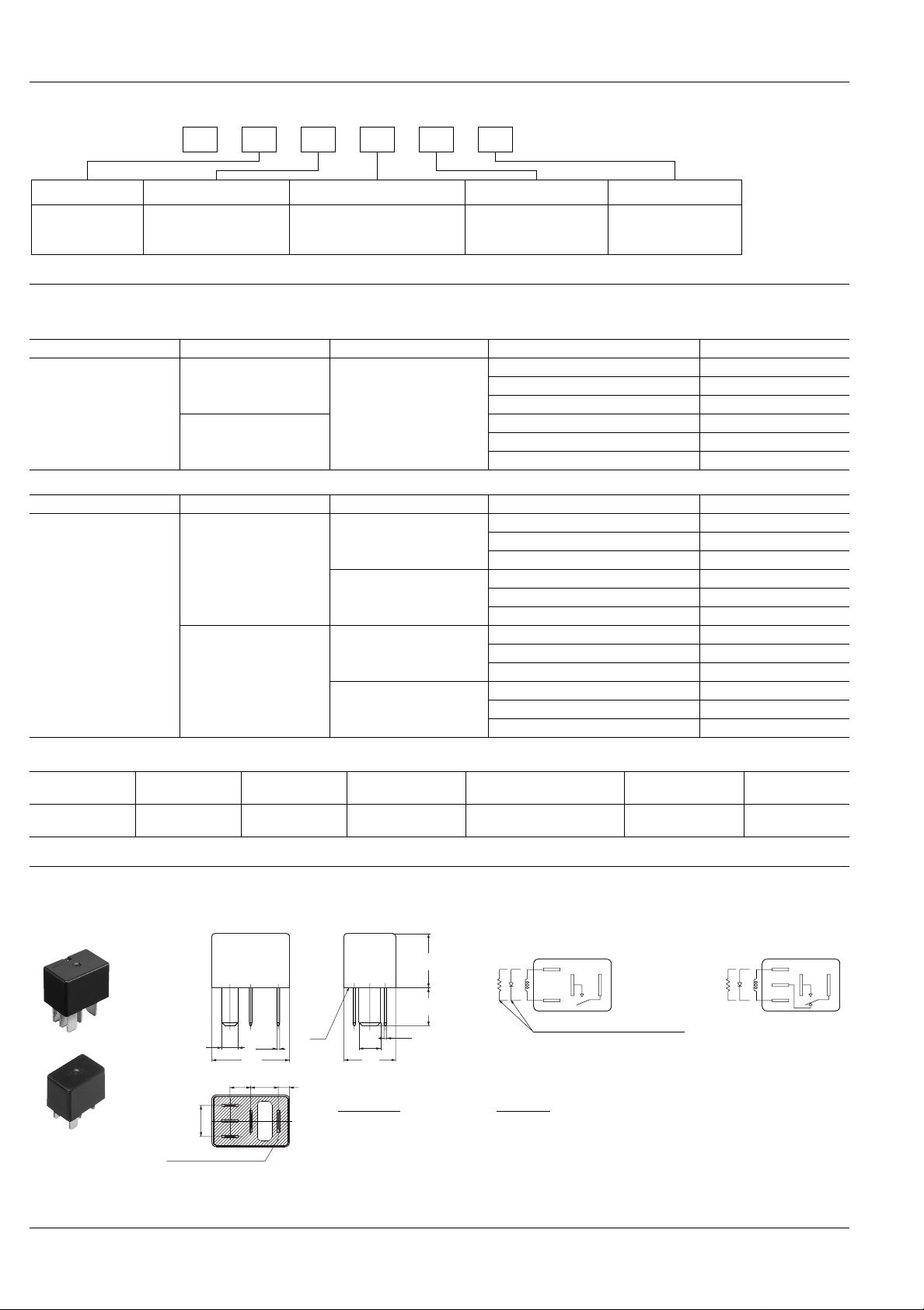
DIMENSIONS
1. Micro ISO terminal type
15.7
.618
11
.433
0.8
.031
Tolerance
±
0.1 ±.004
±
0.3 ±.012
.354
4.8
.189
3.25
.128
*A
0.8
.031
22.5
.886
6
.2368.315
9
6.3
.248
15
.591
Dimension:
Max. 1mm .039 inch:
1 to 3mm .039 to .118 inch:±0.2 ±.008
Sealed by epoxy resin
* Dimensions (thickness and width) of terminal specified in this catalog is measured before pre-soldering.
Intervals between terminals is measured at A surface level.
Min. 3mm .118 inch:
67
Nominal operating
power, W
0.8
Usable voltage
range, V DC
1.0 (with resistor)
Schematic (Bottom view)
1 Form A 1 Form C
2
5
3
1
Including diode type,
including resistor type also available
10 to 16
mm inch
2
5
4
1
3
2
Page 3

CV
2. Micro 280 terminal type
1). Plug-in type
15.7
.618
11
.433
2.8
.110
22.5
.886
16.2
.638
0.8
*A
.031
15
.591
Dimension: Tolerance
7.8
.307
Sealed by epoxy resin
87 87a
86
* Dimensions (thickness and width) of terminal specified in this catalog is measured before pre-soldering.
Intervals between terminals is measured at A surface level.
85
30
Max. 1mm .039 inch:
±
0.1 ±.004
1 to 3mm .039 to .118 inch:±0.2 ±.008
Min. 3mm .118 inch:
±
0.3 ±.012
2). PC board type
16.7
1
.657
.039
3.5
.138
1
*A
.039
22.5
.886
2.8
.110
0.8
.031
15
.591
Schematic (Bottom view)
1 Form A 1 Form C
86
Including diode type,
including resistor type also available
8587
30
Schematic (Bottom view)
1 Form A 1 Form C
86
Including diode type,
including resistor type also available
8587
30
86
mm inch
8587A87
3086
8587A87
30
16.2
.638
7.8
.307
Sealed by epoxy resin
87 87a
86
85
30
Max. 1mm .039 inch:
1 to 3mm .039 to .118 inch:±0.2 ±.008
Min. 3mm .118 inch:
Dimension:
Tolerance
±
0.1 ±.004
±
0.3 ±.012
* Dimensions (thickness and width) of terminal specified in this catalog is measured before pre-soldering.
Intervals between terminals is measured at A surface level.
REFERENCE DATA
1. Coil temperature rise
Point measured: Inside the coil
Contact carrying current: 20A
Coil applied voltage: 13.5V
180
150
120
90
Temperature rise, °C
60
30
0
55 857565
Ambient temperature, °C
2-(2). Electrical life (Motor load)
Tested sample: ACV31212
Quantity: n = 3
Load: Inrush 65A, Steady 14A, 14V DC
Operating frequency: ON 2s, OFF 6s
Ambient temperature: Room temperature
Circuit:
Tested sample
Motor
M
14 V DC
120W
20A
2-(1). Electrical life test (Motor load)
Tested sample: ACV11212
Quantity: n = 3
Load: Inrush 30A, Steady 14A, 13.5V DC
Ambient temperature: Room temperature
Operating frequency: ON 12s, OFF 14s
Circuit:
Tested sample
13.5 V DC
10
8
Pick-up voltage
6
4
Pick-up and drop-out voltage, V
2
0
010
M M
Contact welding: 0 times
Miscontact: 0 times
Drop-out voltage
No. of operations, × 10
4
Max.
X
Min.
Max.
X
Min.
10
8
6
4
Pick-up and drop-out voltage, V
2
0
010
Contact welding: 0 times
Miscontact: 0 times
Pick-up voltage
Drop-out voltage
No. of operations, × 10
Max.
X
Min.
Max.
X
Min.
4
3
Page 4

CV
,,
,,
,,
,,
,,
,,
,,
,,
,,
,,
2-(3). Electrical life (Lamp load)
Tested sample: ACV31212
Quantity: n = 5
Load: 120W, Inrush 80A, Steady 10A, 14V DC
Operating frequency: ON 2s, OFF 13s
Ambient temperature: Room temperature
Circuit:
Tested sample
120W
NOTES
1. Coil operating power
Pure DC current should be applied to the
coil. The wav e form should be rectangular.
If it includes ripple, the ripple factor should
be less than 5%. However, check it with
the actual circuit since the characteristics
may be slightly different.
2. Voltage applied to coil
T o ensure reliable operation, please apply
nominal voltage to the coil. Be w are of the
fact that pick-up voltage and drop-out
voltage vary depending on the ambient
temperature and conditions.
3. Operating life
Operating life varies depending on the
type and load of the coil drive circuit, as
well as factors like the operating
frequency, operating phase and ambient
atmosphere, so please check with actual
equipment.
4.Soldering
We recommend the following soldering
conditions.
1) Automatic soldering
* Preheating: 100°C 212°F, within 2 mins
(PC board solder surface)
* Soldering: 260°C 500°F, within 5 s
2) Hand soldering
* Iron tip temperature: 280 to 300°C 536
to 571°F
* Soldering iron: 30 to 60W
* Soldering time: Within 5 s
10
8
6
4
Pick-up and drop-out voltage, V
2
0
010
5. Usage, transport and storage
conditions
1) Ambient temperature, humidity, and
atmospheric pressure during usage,
transport, and storage of the relay:
(1) T emper ature:
–40 to +85°C –40 to +185°F
(2) Humidity: 5 to 85% RH
(Avoid freezing and condensation.)
The humidity range varies with the
temperature. Use within the range
indicated in the graph below.
Contact welding: 0 times
Miscontact: 0 times
Pick-up voltage
Drop-out voltage
No. of operations, × 10
Humidity, %R.H.
Max.
X
Min.
Max.
X
Min.
4
3) Freezing
Condensation or other moisture may
freeze on the relay when the
temperatures are lower than 0°C 32°F.
This causes problems such as sticking of
movable parts or operational time lags.
4) Low temperature, low humidity
environments
The plastic becomes brittle if the relay is
exposed to a low temperature, low
humidity environment for long periods of
time.
6. Others
1) If in error the relay has been dropped,
,
,,,
(Avoid freezing when
used at temperatures
lower than 0°C 32°F)
–40
–40
85
Tolerance range
,,,,
(Avoid
,,,,,,
,,,,,,,,
condensation when
used at temperatures
higher than 0°C 32°F)
5
,,,,,,,,
,,,,,,,,
0
+32
Temperature, °C °F
,,,,,,
+85
+185
,,
,,,,
the appearance and characteristics
should be checked before use without f ail.
2) Please do not use the coating material
of organic system which contains solvents
such as xylene and toluene for this
product.
(3) Atmospheric pressure: 86 to 106 kPa
2) Condensation
Condensation forms when there is a
sudden change in temperature under high
temperature and high humidity conditions.
Condensation will cause deterioration of
the relay insulation.
12/1/2001 All Rights Reserved, © Copyright Matsushita Electric Works, Ltd.
4
Go To Online Catalog
 Loading...