

Datasheet ACT-PD1M16W-070L4I, ACT-PD1M16N-070L4T, ACT-PD1M16N, ACT-PD1M16Y-070L4T, ACT-PD1M16Y Datasheet (ACT)
...Page 1
www.aeroflex.com
eroflex Circuit Technology - Advanced Multichip Modules © SCD3750 REV A 8/31/98
ACT–PD1M16 Fast Page Mode
F
E
I
D
C
E
R
T
A
E
R
O
F
L
E
X
L
A
B
S
I
N
C
.
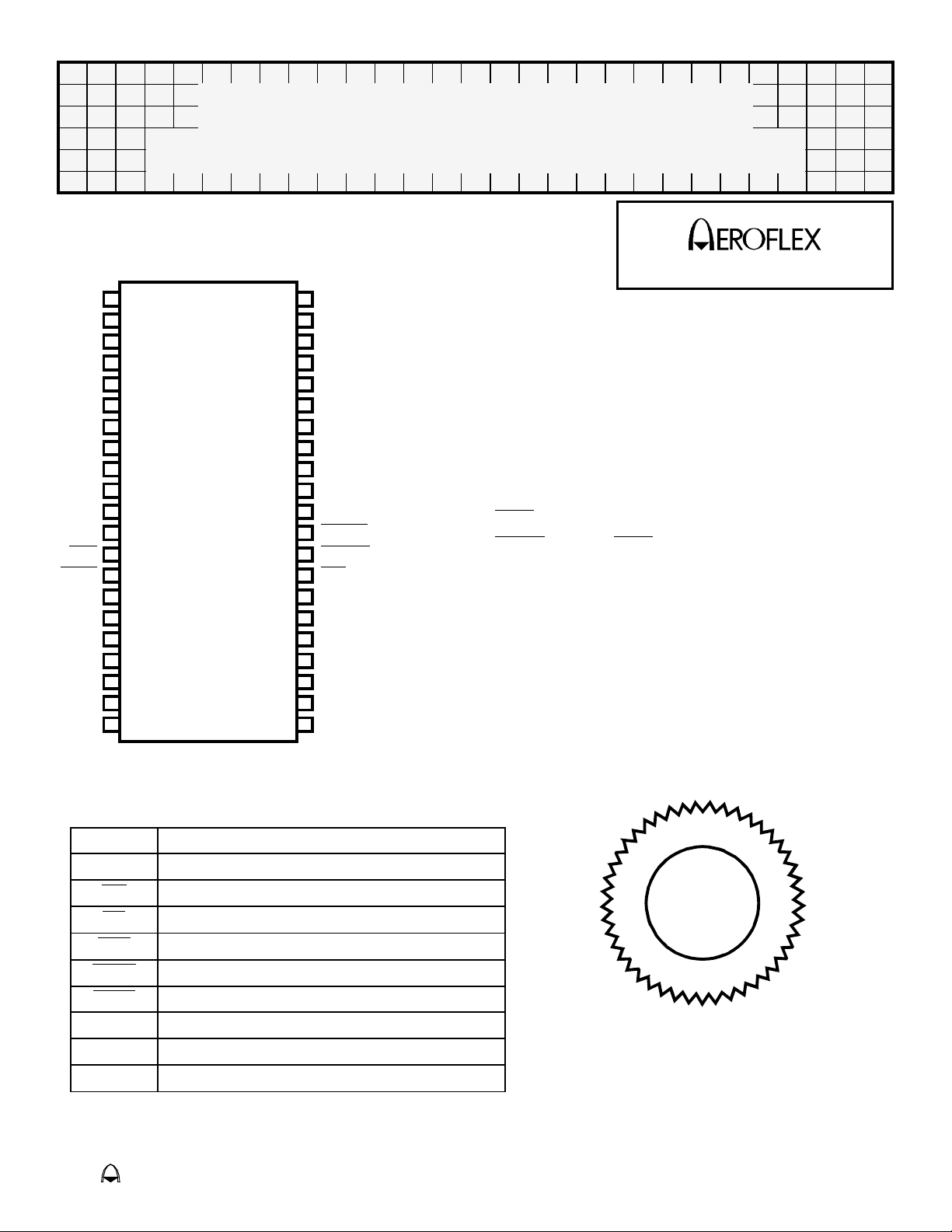
16 Megabit Plastic Monolithic DRAM
Vcc
I/O0
I/O1
I/O2
I/O3
Vcc
I/O4
I/O5
I/O6
I/O7
NC
NC
WE
RAS
NC
NC
A0
A1
A2
A3
Vcc
Pin Configuration
Top View
1
2
3
4
5
6
7
8
9
10
11
12
13
14
15
16
17
18
19
20
21
42
41
40
39
38
37
36
35
34
33
32
31
30
29
28
27
26
25
24
23
22
VSS
I/O15
I/O14
I/O13
I/O12
SS
V
I/O11
I/O10
I/O9
I/O8
NC
LCAS
UCAS
OE
A9
A8
A7
A6
A5
A4
SS
V
CIRCUIT TECHNOLOGY
Features
■ Fast Access Time (tRAC): 70ns
■ Power Supply: 5.0V ± 0.5V
■ Packaging
● 42 Lead Plastic Surface-Mount SOJ (L4)
■ Industrial and Military Temperature Ranges
■ Three-State Unlatched Output
■ Fast Page Mode
■ RAS-Only Refresh
■ xCAS Before RAS Refresh
■ Hidden Refresh
■ 1024 Cycle Refresh in 16ms
■ Low Power Dissipation
■ Long Refresh Period Option
Pin Description
0–9 Address Inputs
A
0-15 Data Input / Output
I/O
WE
Read/Write Enable
OE
RAS
UCAS
LCAS
CC +5.0V Power Supply
V
SS Ground
V
NC Not Connected
Upper Byte Control / Column Address Strobe
Lower Byte Control / Column Address Strobe
Output Enable
Row Address Strobe
ISO
900
1
I
Page 2
Absolute Maximum Ratings
Symbol Parameter MINIMUM MAXIMUM Units
T
C
T
STG
I
OS
P
T
V
CC
V
T
Stresses beyond those listed under “absolute maximum ratings” may cause permanent damage to the device. These are
stress ratings only, and functional operation of the device at these or any other conditions beyond those indicated under
“recommended operating conditions” is not implied. Exposure to absolute-maximum rated conditions for extended periods may
affect device reliability.
* All voltage values are with respect to Vss.
Case Operating Temp.
Storage Temperature
Short Circuit Output Current
Power Dissipated
Supply Voltage Range
Voltage Range on any Pin*
-55 +125 °C
-55 +150 °C
- 50 mA
- 1 W
-1.0 +7.0 V
-1.0 +7.0 V
Recommended Operating Conditions
Symbol Parameter Minimum Maximum Units
V
CC
V
IH
V
IL
T
CM
T
CI
Power Supply Voltage
Input High Voltage
Input Low Voltage
Operating Temp. (Mil)
Operating Temp. (Ind.)
+4.5 +5.5 V
+2.4 - V
- +0.8 V
-55 +125 °C
-40 +85 °C
Capacitance
(V
= 0V, f = 1MHz, Tc = 25°C)
IN
Symbol Parameter Maximum Units
C
I(A)
C
I(RC)
C
I(OE)
C
I(WE)
C
O
These parameters are guaranteed by design but not tested.
A
Input Capacitance
0-9
RAS and CAS Input Capacitance
OE Input Capacitance
WE Input Capacitance
Output Capacitance
10 pF
10 pF
10 pF
10 pF
15 pF
DC Characteristics
(VCC = 5.0V, VSS = 0V, TCI or TCM)
Parameter Sym Conditions Min Max Units
Output Low Voltage
Output High Voltage
Input Leakage Current
Output Leakage Current
Read or Write Cycle Current
1,2
V
IOL = 4.2 mA
OL
V
IOH = -5 mA
OH
I
VI=0to+6.5V, All others 0V to V
L
I
I
CC1
O
VO=0toV
V
= 5.5V, minimum cycle
CC
CAS high
CC,
CC
- 0.4 V
2.4 V
-10 +10 µA
-10 +10 µA
190 mA
Aeroflex Circuit Technology SCD3750 REV A 8/31/98 Plainview NY (516) 694-6700
2
Page 3
DC Characteristics (continued)
(VCC = 5.0V, VSS = 0V, T CI or TCM)
Parameter Sym Conditions Min Max Units
VIH = 2.4V (TTL), After 1 memory cycle,
I
CC2
Standby Current
I
CC3
Average Page Current
1. Measured with a maximum of one address change while RAS = VIL.
2. Measured with a maximum of one address change while CAS
2
I
CC4
and CAS high
RAS
VIH = Vcc - 0.05V (CMOS), After 1 memory
cycle, RAS
and CAS high
RAS low, CAS cycling
= VIH.
- 2 mA
- 1 mA
- 100 mA
AC Characteristics*
(VCC = 5.0V ±10%, VSS= 0V, TCI or TCM)
Parameter
Access Time from Column-Address
Low Access Time from CAS
CAS
Column Access Time from CAS
Precharge
Access Time from RAS
Access Time
OE
1
Output Buffer Turn-off Delay
Output Buffer Turn-off Delay Time from OE
* Valid data is presented at the outputs after all access times are satisfied but can go from the high-impedance
state to an invalid-data state prior to the specified access times as the outputs are driven when CAS
OFF and tOEZ are specified when the outputs are no longer driven. The outputs are disabled by bringing either
1. t
or CAS high.
OE
1
Sym Min Max Units
AA - 35 ns
t
tCAC - 20 ns
tCPA - 40 ns
tRAC - 70 ns
tOEA - 20 ns
tOFF 0 15 ns
tOEZ 0 15 ns
goes low.
AC Characteristics
(VCC = 5.0V, VSS = 0V, TCI or TCM)
Parameter
Cycle Time, Read or Write Random 1
Cycle Time, Fast Page Mode Read or Write
Cycle Time, Fast Page Mode Read-Modify-Write
Pulse Duration, RAS Low Fast Page Mode
Pulse Duration, RAS Low Nonpage Mode
Pulse Duration, CAS Low
4
Pulse Duration, CAS High Precharge Time
Pulse Duration, RAS High Precharge Time
Pulse Duration, WE Low
Setup Time, Column Address before CAS Low
Setup Time, Row Address before RAS Low
Setup Time, Data
5
Setup Time, WE High before CAS Low
Setup Time, WE Low before CAS High
Setup Time, WE Low before RAS High
1,2
3
3
Sym Min Max Units
RC 130 -
t
tPC 45 -
1
tPRWC 90 -
tRASP 70 200,000
tRAS 70 10,000 ns
tCAS 20 10,000 ns
tCP 10 -
tRP 50 -
tWP 15 -
tASC 0 -
tASR 0 - ns
ns
ns
ns
ns
ns
ns
ns
ns
tDS 0 - ns
t
t
t
RCS
CWL
RWL
0 - ns
20 - ns
20 - ns
Aeroflex Circuit Technology SCD3750 REV A 8/31/98 Plainview NY (516) 694-6700
3
Page 4

AC Characteristics (continued)
(VCC = 5.0V, VSS = 0V, TCI or TCM)
Parameter
Setup Time, WE Low before CAS Low (early-write operation only)
Hold Time, Column Address after CAS Low
Hold Time, Data
5
Hold Time, Row Address after RAS Low
Hold Time, WE High after CAS High 6
Hold Time, WE High after RAS High 6
1. All cycle times assume tT= 5ns, reference to VIH (min) and VIL (max).
2. To assume t
3. In read-write cycle, t
4. In read-write cycle, t
5. Referenced to the later of xCAS
6. Either t
PC min, tASC should be ≥ tCP.
RWD and tRWL must be observed.
CWD and tCWL must be observed.
or WE in write operations.
RRH or tRCH must be satisfied for a read cycle.
AC Characteristics
(VCC = 5.0V, VSS = 0V, TCI or TCM)
Parameter
WE Low before CAS Low Hold Time (early-write operation only)
Command Hold Time
OE
Referenced to OE Hold Time
RAS
from CAS Precharge (Fast Page Mode)
RAS
Column Address to WE
Low to CAS High Delay Time (CBR refresh only)
RAS
High to RAS Low Delay Time (CAS to RAS Precharge Time)
CAS
Low to CAS High Delay Time (CAS Hold Time)
RAS
Low to RAS Low Delay Time (CAS Set-up Time)
CAS
Low to WE Low Delay Time (read-write operation only)
CAS
to Data Delay Time
OE
Low to Column Address Delay Time 1
RAS
Column Address to RAS
Low to CAS Low Delay Time 1
RAS
High to CAS Low Precharge Time
RAS
Low to RAS High Delay Time (RAS Hold Time)
CAS
Low to WE Low Delay Time (read-write operation only)
RAS
Low after CAS Precharge Delay Time (read-write operation only)
WE
Refresh Time Interval
Transition time
1. The maximum value is specified only to assure access time
2. Transition times (rise and fall) for RAS
2
Low Delay Time (read-write operation only)
High Delay Time
and xCAS are to be a minimum of 3ns and a maximum of 30ns.
Sym Min Max Units
t
WCS 0 - ns
CAH 15 - ns
t
tDH
RAH
t
RCH
t
RRH
t
Sym Min Max Units
WCH 15 - ns
t
tOEH 15 - ns
tROH 10 - ns
tRHCP 40 - ns
tAWD 60 - ns
tCHR 15 - ns
tCRP 5 - ns
tCSH 70 - ns
tCSR 5 - ns
tCWD 45 - ns
tOED 15 - ns
tRAD 15 35 ns
tRAL 35 - ns
tRCD 20 50 ns
tRPC 5 - ns
tRSH 20 - ns
RWD 95 - ns
t
tCWD 65 - ns
tREF 16 ms
15 - ns
10 - ns
0 - ns
0 - ns
tT 3 50 ns
Aeroflex Circuit Technology SCD3750 REV A 8/31/98 Plainview NY (516) 694-6700
4
Page 5

AC Test Circuit
Current Source
IOL
Z ~ 1.5 V (Bipolar Supply)
To Device Under Test
CL =
50 pF
Current Source
Notes: 1) VZ is programmable from -2V to +7V.
OL and IOH programmable from 0 to 16 mA.
2) I
3) Tester Impedance Z
O =75Ω.
4) VZ is typically the midpoint of VOH and VOL.
OL and IOH are adjusted to simulate a typical resistance load circuit.
5) I
6) ATE Tester includes jig capacitance.
V
IOH
Parameter Typical Units
Input Pulse Level 0 – 3.0 V
Input Rise and Fall 5 ns
Input and Output Reference Level 1.5 V
Output Timing Reference Level 1.5 V
Aeroflex Circuit Technology SCD3750 REV A 8/31/98 Plainview NY (516) 694-6700
5
Page 6

OPERATIONS
OPERATIONS
low time and the xCAS page-mode cycle
RAS
time used. With minimum xCAS
time, all columns can be accessed without
intervening RAS
cycles.
page-cycle
DUAL CAS
Two CAS
provided to give independent control of the 16
data-I/O pins (I/O0-15), with LCAS
corresponding to I/O0-7 and UCAS
corresponding to I/O8-15. For read or write
cycles, the column address is latched on the
first xCAS
enables its corresponding I/Ox pin with data
associated with the column address latched
on the first falling xCAS
setup and hold parameters are referenced to
the first falling xCAS
from xCAS
parameter t
individual xCAS
In order to latch in a new column address,
both xCAS
column-precharge time (see parameter t
is measured from the last xCAS
the first xCAS
Keeping a column address valid while
toggling xCAS
time, t
must be brought low before the other xCAS is
taken high.
For early-write cycles, the data is latched on
the first xCAS
have the corresponding xCAS
into. Each xCAS
order to ensure writing into the storage cell.
To latch a new address and new data, all
xCAS
pins (LCAS and UCAS) are
falling edge. Each xCAS going low
edge. All address
edge. The delay time
low to valid data out (see
CAC) is measured form each
to its corresponding I/Ox pin.
pins must be brought high. The
CP )
rising edge to
falling edge of the new cycle.
requires a minimum setup
CLCH. During tCLCH at least one xCAS
falling edge. Only the I/Os that
low are written
must meet tCAS minimum in
pins must be high and meet tCP.
PAGE MODE
Page-mode operation allows faster memory
access by keeping the same row address
while selecting random column addresses.
The time for row-address setup and hold and
address multiplex is eliminated. The
maximum number of columns that can be
accessed is determined by the maximum
Unlike conventional page-mode DRAMs, the
column address buff-ers in this device are
activated on the falling edge of RAS
buffers act as transparent or flow-through
latches while xCAS
the first xCAS
This feature allows the devices to operate at a
higher data bandwidth than conventional
page-mode parts because data retrieval
begins as soon as the column address is valid
rather than when xCAS
performance improvement is referred to as
enhanced page mode. A valid column
address may be presented immediately after
t
RAH (row-address hold time) has been
satisfied, usually well in advance of the falling
edge of xCAS
after t
low) if tAA maximum (access time from
column address) has been satisfied. In the
event that column addresses for the next page
cycle are valid at the time xCAS
minimum access time for the next cycle is
determined by t
edge of the last xCAS
CAC maximum (access time from xCAS
is high. The falling edge of
latches the column addresses.
transitions low. This
. In this case, data is obtained
goes high,
CPA (access time from rising
).
. The
ADDRESS: A0-9
Twenty address bits are required to decode 1
of 1048576 storage cell locations. For the
ACTPD1M16, 10 row-address bits are set up
on A0 through A9 and latched onto the chip
by RAS
on A0 through A9 and latched onto the chip
by the first xCAS
stable on or before the falling edge of RAS
and xCAS. RAS is similar to a chip enable in
that it activates the sense amplifiers as well as
the row decoder. xCAS
select, activating its correspond-ing output
buffer and latching the address bits into the
column-address buffers.
. Ten, column-address bits are set up
. All addresses must be
is used as a chip
Aeroflex Circuit Technology SCD3750 REV A 8/31/98 Plainview NY (516) 694-6700
6
Page 7

WRITE ENABLE (WE)
The read or write mode is selected through
WE
. A logic high on WE selects the read
mode and a logic low selects the write mode.
The data inputs are disabled when the read
mode is selected. When WE
xCAS
high-impedance state for the entire cycle,
permitting a write operation with OE
grounded.
DATA IN (I/O
Data is written during a write or
read-modify-write cycle. Depending on the
mode of operation, the falling edge of xCAS
WE
In an early-write cycle, WE
prior to xCAS
first occurring xCAS
referenced to this signal. In a delayed-write or
read-modify-write cycle, xCAS
and the data is strobed in by WE
and hold times referenced to this signal. In a
delayed-write or read-modify-write cycle, OE
must be high to bring the output buffers to the
high-impedance state prior to impressing data
on the I/O lines.
(early write), data out remains in the
0-15)
strobes data into the on-chip data latch.
and the data is strobed in by the
with setup and hold times
goes low prior to
or
is brought low
is already low
with setup
in the low-impedance state until either OE
xCAS
*Output Enable can be held low during write cycles.
is brought high.
or
RAS-ONLY REFRESH
A refresh operation must be performed at
least once every 16ms (128ms for long
refresh periods) to retain data. This can be
achieved by strobing each of the 1024 rows
(A0-9). A normal read or write cycle refreshes
all bits in each row that is selected. A
RAS
-only operation can be used by holding
both xCAS
conserving power as the output buffers
remain in the high-impedance state.
Externally generated addresses must be used
for a RAS
at the high (inactive) level,
-only refresh.
HIDDEN REFRESH
Hidden refresh can be performed while
maintaining valid data at the output pin. This
is accomplished by holding xCAS
a read operation and cycling RAS
specified precharge period, similar to a
RAS
-only refresh cycle. The external address
is ignored and the refresh address is
generated internally.
at VIL after
after a
DATA OUT (I/O
Data out is the same polarity as data in. The
output is in the high-impedance (floating)
state until xCAS
read cycle, the output becomes valid after the
access time interval t
the negative transition of xCAS
t
RAC and tAA are satisfied.
and OE are brought low. In a
OUTPUT ENABLE (OE
OE
controls the impedance of the output
buffers. When OE
in the high-impedance state. Bringing OE
during a normal cycle activates the output
buffers, putting them in the low-impedance
state. It is necessary for both RAS
to be brought low for the output butters to go
into the low-impedance state, and they remain
0-15)
CAC (which begins with
) as long as
)*
is high, the buffers remain
low
and xCAS
xCAS
-BEFORE-RAS (xCBR)
REFRESH
xCBR
one xCAS
parameter t
fails (see parameter tCHR). For succesive
xCBR
while cycling RAS
ignored and the refresh address is generated
internally.
refresh is utilized by bringing at least
low earlier than RAS (see
CSR) and holding it low after RAS
refresh cycles, xCAS can remain low
. The external address is
POWER UP
To achieve proper device operation, an initial
pause of 200µs followed by a minimum of
eight initialization cycles is required after
power up to full Vcc level. These eight
initialization cycles must include at least one
refresh (RAS
-only or xCBR) cycle.
Aeroflex Circuit Technology SCD3750 REV A 8/31/98 Plainview NY (516) 694-6700
7
Page 8

Package Outline "L4" — SOJ Package, 42 Leads
10.16 (0.400)
±0.13 (0.005)
1 21
Pin 1 Identifier (Do not block with Label)
All dimensions in millimeters
27.30 (1.075)
±0.13 (0.005)
1.27
TYP
(0.050)
Dimensions in millimeters mm
Dimensions in inches ()
2242
.46
(.018
11.18 (0.440)
±0.13 (0.005)
2.69 (0.106) TYP
±0.05
±0.002)
TYP
0.20 (0.008) TYP
9.40 (0.370)
±0.25 (0.070)
3.51 (0.138)
±0.25 (0.01)
Aeroflex Circuit Technology SCD3750 REV A 8/31/98 Plainview NY (516) 694-6700
8
Page 9

CIRCUIT TECHNOLOGY
Ordering Information (Typical)
Model Number Options Speed Package
ACT-PD1M16N–070L4I None 70ns 42 Lead SOJ
ACT-PD1M16W–070L4I Burn-in 70ns 42 Lead SOJ
ACT-PD1M16X–070L4I Temp Cycle 70ns 42 Lead SOJ
ACT-PD1M16Y–070L4I Temp Cycle & Burn-in 70ns 42 Lead SOJ
ACT-PD1M16N–070L4T None 70ns 42 Lead SOJ
ACT-PD1M16W–070L4T Burn-in 70ns 42 Lead SOJ
ACT-PD1M16X–070L4T Temp Cycle 70ns 42 Lead SOJ
ACT-PD1M16Y–070L4T Temp Cycle & Burn-in 70ns 42 Lead SOJ
Aeroflex Circuit
Technology
Plastic Path
Memory Type
D = Plastic DRAM
Memory Depth, Locations
Memory Width, Bits
Options
N = None
W = Burn-in
X = Temperature Cycle *
Y = Burn-in & Temperature Cycle *
Memory Speed, ns
070 = 70ns
*
Part Number Breakdown
\\\
ACT- P D 1M 16 N– 070 L4 T
* Screened to the test methods of MIL-STD-883
Electrical Testing
I = Industrial Temp, -40°C to +85°C
T = Military Temp, -55°C to +125°C
Package Type & Size
L4 = 42 Pin Plastic SOJ
Aeroflex Circuit Technology
35 South Service Road
Plainview New York 11830
Aeroflex Circuit Technology SCD3750 REV A 8/31/98 Plainview NY (516) 694-6700
Toll Free Inquiries: 1-(800) 843-1553
9
Telephone: (516) 694-6700
FAX: (516) 694-6715
 Loading...