

Page 1
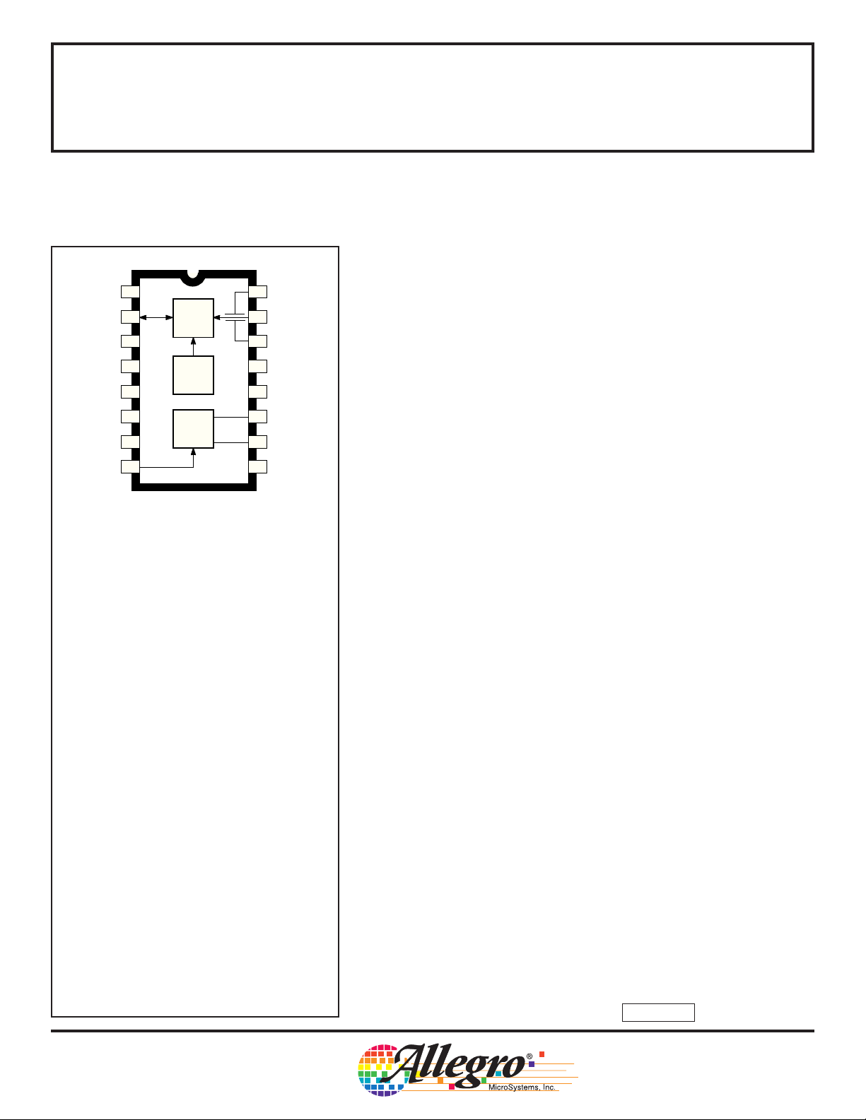
TIMER START
I / O
LOW-V SET
TIMER OUT
LED
+ SUPPLY
TIMING RES.
FEEDBACK
5347
WITH INTERCONNECT AND TIMER
required features for an ionization-type smoke detector. A networking
1
2
3
4
5
6
7
89
LOGIC
OSC. &
TIMING
V
DD
HORN
DRIVER
16
GUARD
2
15
DETECT. IN
14
GUARD
1
SENSITIVITY
13
SET
12
OSC. CAP.
11
HORN
2
10
HORN
1
V
– SUPPLY
SS
capability allows as many as 125 units to be interconnected so that if
any unit senses smoke, all units will sound an alarm. In addition,
special features are incorporated to facilitate alignment and test of the
finished smoke detector. This device is designed to comply with
Underwriters Laboratories Specification UL217.
a minimum by powering down the device for 1.66 seconds and sensing
smoke for only 10 ms. Every 24 on/off cycles, a check is made for low
battery condition. By substituting other types of sensors, or a switch
for the ionization detector, this very-low power device can be used in
numerous other battery-operated safety/security applications.
Data Sheet
26110.2
SMOKE DETECTOR
The A5347CA is a low-current, CMOS circuit providing all of the
The internal oscillator and timing circuitry keeps standby power to
Dwg. PC-004
ABSOLUTE MAXIMUM RATINGS
(Voltages are referenced to VSS)
Supply Voltage Range,
VDD................................ -0.5 V to +15 V
Input Voltage Range,
V
........................ -0.3 V to V
IN
Input Current, I
............................... 10 mA
IN
Operating Temperature Range,
T
..................................... 0°C to +50°C
A
Storage Temperature Range,
T
............................... -55°C to +125°C
S
CAUTION: CMOS devices have input static
protection but are susceptible to damage when
exposed to extremely high static electrical
charges.
+ 0.3 V
DD
The A5347CA is supplied in a low-cost, 16-pin dual in-line plastic
package. It is rated for continuous operation over the temperature
range of 0°C to +50°C.
FEATURES
■ Interconnect Up to 125 Detectors
■ Piezoelectric Horn Driver
■ Guard Outputs for Detector Input
■ Pulse Testing for Low Battery
■ Power-ON Reset
■ Internal Timer & Control for Reduced Sensitivity
■ Built-In Hysteresis Reduces False Triggering
Always order by complete part number: A5347CA .
Page 2
5347
SMOKE DETECTOR
with INTERCONNECT
and TIMER
FUNCTIONAL BLOCK DIAGRAM AND TYPICAL APPLICATION
+ SUPPLY
9 V
3
LOW-V
SET
13
SENSITIVITY
SET
– SUPPLY
9
V
SS
V
DD
6
–
+
+
–
+
–
14 15 16
GUARD GUARD
DETECT.
IN
12
I / O
2
LOGIC
V
DD
POWER-ON
OSCILLATOR
& TIMING
RESET
1
TIMER
START
FEEDBACK
8
11
HORN
2
10
HORN
1
5
LED
TIMING RES.
7
OSC. CAP.
12
4
TIMER OUT
+V
+V
115 Northeast Cutoff, Box 15036
Worcester, Massachusetts 01615-0036 (508) 853-5000
Copyright © 1995, Allegro MicroSystems, Inc.
Dwg. FC-001-2
Page 3

5347
SMOKE DETECTOR
with INTERCONNECT
and TIMER
ELECTRICAL CHARACTERISTICS at T
R
= 8.2 MΩ (unless otherwise noted).
7
Characteristic Pin Test Conditions Min. Typ. Max. Units
Supply Voltage Range 6 Operating 6.0 9.0 12 V
Detector Input Current 15 0 to 40% RH, V
Input Offset Voltage 14-15 Active Guard — — ±100 mV
Hysteresis 13 No Alarm to Alarm 90 130 170 mV
Common Mode Range 14-15 Guard Amplifier 2.0 — V
Active Guard Impedance 14 to V
Oscillator Period 12 No Alarm 1.34 1.67 2.00 s
Oscillator Pulse Width 4 8.0 10 12 ms
Test
16-15 Active Guard — — ±100 mV
15-13 Detect Comparator — — ±50 mV
13-15 Smoke Comparator 0.5 — V
16 to V
= +25°C, V
A
SS
SS
Alarm 32 40 48 ms
= 9.0 V, VSS = 0 V, C
DD
= 0 to 9.0 V — — ±1.0 pA
IN
—10—kΩ
— 500 — kΩ
= 0.1 µF,
12
Limits
DD
DD
- 0.5 V
- 2.0 V
Timer Period 4 After Pin 1 High-to-Low, No Smoke 8.0 10 12 min
Low Voltage Threshold 6 T
Sensitivity Adj. Voltage 13 V
Horn Output Voltage 10-11 I
Horn Output ON Time 10-11 Alarm 120 160 208 ms
Horn Output OFF Time 10-11 Alarm 60 80 104 ms
Timer Start Logic Levels 1 V
Timer Start Input Current 1 V
NOTE 1: Negative current is defined as coming out of (sourcing) the specified device pin.
NOTE 2: Alarm (Smoke) Condition is defined as V
< V
; No Alarm (No Smoke) Condition as V15 > V13.
15
13
= 0 to 50°C 7.2 — 7.8 V
A
, pin 13 open circuit 48.5 50 51.5 %
13/VDD
= 16 mA, VDD = 9.0 V — 0.1 0.5 V
OUT
= 16 mA, VDD = 7.2 V — — 0.9 V
I
OUT
= -16 mA, VDD = 9.0 V 8.5 8.8 — V
I
OUT
= -16 mA, VDD = 7.2 V 6.3 — — V
I
OUT
Low Battery 8.0 10 12 ms
Low Battery 32 40 48 s
IH
V
IL
= 9.0 V 20 — 80 µA
IN
3.5 — — V
— — 1.5 V
Continued next page . . .
Page 4

5347
SMOKE DETECTOR
with INTERCONNECT
and TIMER
ELECTRICAL CHARACTERISTICS continued
Characteristic Pin Test Conditions Min. Typ. Max. Units
Timer Out Output Current 4 V
LED Output ON Current 5 V
LED Output ON Time 5 8.0 10 12 ms
LED Output OFF Time 5 No Alarm, In Standby 32 40 48 s
I/O Current 2 No Alarm, V
I/O Alarm Voltage 2 External “Alarm” In 3.0 — — V
I/O Delay 2 “Alarm” Out — 3.0 — s
Supply Current 6 V
NOTE 1: Negative current is defined as coming out of (sourcing) the specified device pin.
NOTE 2: Alarm (Smoke) Condition is defined as V
Test
15
= 0.5 V 500 — — µA
OUT
= 7.2 V, V
DD
No Alarm, Timer Mode After Pin 1
High-to-Low 8.0 10 12 s
Alarm, V
V
< V
; No Alarm (No Smoke) Condition as V15 > V13.
13
I/O
= 9.0 V, No Alarm, No Loads — 5.0 9.0 µA
DD
= 12 V, No Alarm, No Loads — — 12 µA
DD
= 1.0 V 10 — — mA
OUT
= VDD - 2.0 V 25 — 60 µA
I/O
= VDD - 2.0 V -7.5 — — mA
Limits
CIRCUIT DESCRIPTION
The A5347CA is a low-current CMOS circuit providing all of the
required features for an ionization-type smoke detector.
Oscillator. An internal oscillator operates with a period of 1.67
seconds during no-smoke conditions. Every 1.67 seconds, internal
power is applied to the entire circuit and a check is made for smoke.
Every 24 clock cycles (40 seconds), the LED is pulsed and a check
is made for low battery by comparing VDD to an internal reference.
Since very-low currents are used in the device, the oscillator capacitor
at pin 12 should be a low-leakage type (PTFE, polystyrene, or
polypropylene).
Detector Circuitry. When smoke is detected, the resistor divider
network that sets the sensitivity (smoke trip point) is altered to increase
the sensitivity set voltage (pin 13) by typically 130 mV with no external
connections to pins 3 or 13. This provides hysteresis and reduces
false triggering. An active guard is provided on both pins adjacent to
the detector input (pin 15). The voltage at pins 14 and 16 will be within
100 mV of the input. This will keep surface leakage currents to a
minimum and provide a method of measuring the input voltage without
loading the ionization chamber. The active guard amplifier is not
power strobed and thus provides constant protection from surface
leakage currents. The detector input has internal diode protection
against static damage.
115 Northeast Cutoff, Box 15036
Worcester, Massachusetts 01615-0036 (508) 853-5000
Page 5

50 kΩ
200 kΩ
1 MΩ
200 kΩ
0.001 µF
5347
SMOKE DETECTOR
with INTERCONNECT
and TIMER
Alarm Circuitry. If smoke is detected, the
oscillator period changes to 40 ms and the
horn is enabled. The horn output is typically
160 ms ON, 80 ms OFF. During the OFF
time, smoke is again checked and will inhibit
further alarm output if smoke is not sensed.
During smoke conditions the low battery
alarm is inhibited and the LED is driven at a
1 Hz rate.
Sensitivity Adjust. The detector sensitivity
to smoke is set internally by a voltage divider
connected between VDD and VSS. The
sensitivity can be externally adjusted to the
individual characteristics of the ionization
chamber by connecting a resistor between
pin 13 and VDD, or between pin 13 and VSS.
Low Battery. The low battery threshold is
set internally by a voltage divider connected
between VDD and VSS. The threshold can be
increased by connecting a resistor between
pin 3 and VDD. The threshold can be decreased by connecting a resistor between
pin 3 and VSS. The battery voltage level is
checked every 40 seconds during the 10 mA,
10 ms LED pulse. If an LED is not used, it
should be replaced with an equivalent
resistor (typically 500 Ω to 1000 Ω) such that
the battery loading remains at 10 mA.
Timer. An internal timer is provided that can
be used in various configurations to allow for
a period of reduced smoke detector sensitivity (“hush”). When a high-to-low transition
occurs at pin 1, the internal timer is reset,
the timer mode enabled, and the circuit reset
to a no alarm condition. The LED will flash
at a 10 second rate. If the level of smoke is
increased such that the reduced sensitivity
level is reached, the device will go into the
alarm condition. The timer, however, will
continue to completion of the nominal 10-1/4
minute period (368 clock cycles). If the timer
mode is not used, pin 1 should be tied low.
TYPICAL APPLICATION
NOTE 4
LOGIC
OSC. &
TIMING
HORN
DRIVER
NOTE 2
200 kΩ
PUSH
16
15
14
13
12
0.1 µF
11
10
V
SS
TO
TEST
NOTE
1
Dwg. EC-005-2
9 V
TIMER
MODE
TO
OTHER
UNITS
NOTE 1: Use an external resistor to adjust sensitivity for a particular smoke
NOTE 2: Select resistor to reduce sensitivity during timer mode.
NOTE 3: A resistor to ground or VDD may be added to this pin to modify low battery
NOTE 4: Reverse battery protection must be supplied externally.
200 Ω
NOTE
3
1 µF
chamber.
voltage threshold.
1
2
3
4
330 Ω
5
6
V
8.2 MΩ
DD
7
89
I/O. A connection is provided at pin 2 to allow multiple smoke detectors to be commoned. If any single unit detects smoke (I/O is driven
high), all connected units will sound their associated horns after a
nominal 3 second delay. The LED is suppressed when an alarm is
signaled from an interconnected unit.
Testing. On power up, all internal counters are reset. Internal test
circuitry allows for low battery check by holding pins 8 and 12 low
during power up, then reducing VDD and monitoring HORN1 (pin 10).
All functional tests can be accelerated by driving pin 12 with a 2 kHz
square wave. The 10 ms strobe period must be maintained for proper
operation of the comparator circuitry.
Page 6

5347
SMOKE DETECTOR
with INTERCONNECT
and TIMER
TIMING DIAGRAMS IN TYPICAL APPLICATION
NON-TIMER MODE
V12
OSC. CAP
INTERNAL
CLOCK
LED
SMOKE
COMPARATOR
HORN
SMOKE
CHAMBER
NO ALARM
NO LOW BATTERY
STANDBY MODE
1.67 s
24 CLOCK CYCLES
LED OFF
SAMPLE
V15 > V13 (NO SMOKE)
10 ms
ALARM
NO LOW BATTERY
40 ms
24 CLOCK CYCLES
LED
ON
12 CLOCK CYCLES 6 CLOCK CYCLES 6 CLOCK CYCLES
HORN
OFF
ON
V15 < V13 (SMOKE)
ALARM AND
LOW BATTERY
LOW BATTERY
30 CLOCK CYCLES
NO ALARM
LOW BATTERY
WARNING
Dwg. WC-003
TIMER MODE
V12
OSC. CAP
INTERNAL
CLOCK
TIMER
START
TIMER
OUT
LED
HORN
1.67 s
10 ms
368 CLOCK CYCLES
6 CLOCK CYCLES
LED
ON
OUTPUTS OFF (HIGH Z)
END OF TIMER
NOTIFICATION
Dwg. WC-005
115 Northeast Cutoff, Box 15036
Worcester, Massachusetts 01615-0036 (508) 853-5000
Page 7

5347
SMOKE DETECTOR
with INTERCONNECT
and TIMER
INTERNAL
CLOCK
I/O OPERATION
REMOTE ALARM MODE
40 ms
4 CYCLES 2 CYCLES
1.67 s
HORN
V2 IN
I/O
INTERNAL
CLOCK
HORN
ON
OFF
HORN NOT SELF COMPLETING
WHEN IN REMOTE ONLY ALARM
LOCAL ALARM MODE
HORN
V2 OUT
I/O
HORN
ON
OFF
72 CLOCK CYCLES
Dwg. WC-004
Page 8

5347
SMOKE DETECTOR
with INTERCONNECT
and TIMER
16
0.280
0.240
Dimensions in Inches
(controlling dimensions)
0.014
9
0.008
0.300
BSC
0.430
MAX
0.210
MAX
7.11
6.10
0.015
MIN
1
0.070
0.045
16
1
1.77
1.15
0.022
0.014
8
0.775
0.100
BSC
0.735
Dimensions in Millimeters
(for reference only)
9
8
19.68
18.67
2.54
BSC
0.005
0.150
0.115
0.13
MIN
MIN
0.355
0.204
Dwg. MA-001-16A in
10.92
MAX
7.62
BSC
5.33
MAX
0.39
MIN
0.558
0.356
NOTES: 1. Lead thickness is measured at seating
plane or below.
2. Lead spacing tolerance is non-cumulative.
3. Exact body and lead configuration at
vendor’s option within limits shown.
3.81
2.93
Dwg. MA-001-16A mm
Allegro MicroSystems, Inc. reserves the right to make, from time to time, such departures from the
detail specifications as may be required to permit improvements in the design of its products.
Components made under military approvals will be in accordance with the approval requirements.
The information included herein is believed to be accurate and reliable. However, Allegro
MicroSystems, Inc. assumes no responsibility for its use; nor for any infringements of patents or other
rights of third parties which may result from its use.
115 Northeast Cutoff, Box 15036
Worcester, Massachusetts 01615-0036 (508) 853-5000
 Loading...