

Page 1
AiT Semiconductor Inc.
www.ait-ic.com
A4775
SWITCH
70mΩ, 3A SMART UNIVERSAL POWER SWITCH
DESCRIPTION
FEATURES
The A4775 is a low voltage, high performance
single N-MOSFET power switch, designed for
power rail on/off control with low R
DS(ON)
≈70mΩ and
full protection functions. The A4775 equipped with a
charge pump circuitry to drive the internal MOSFET
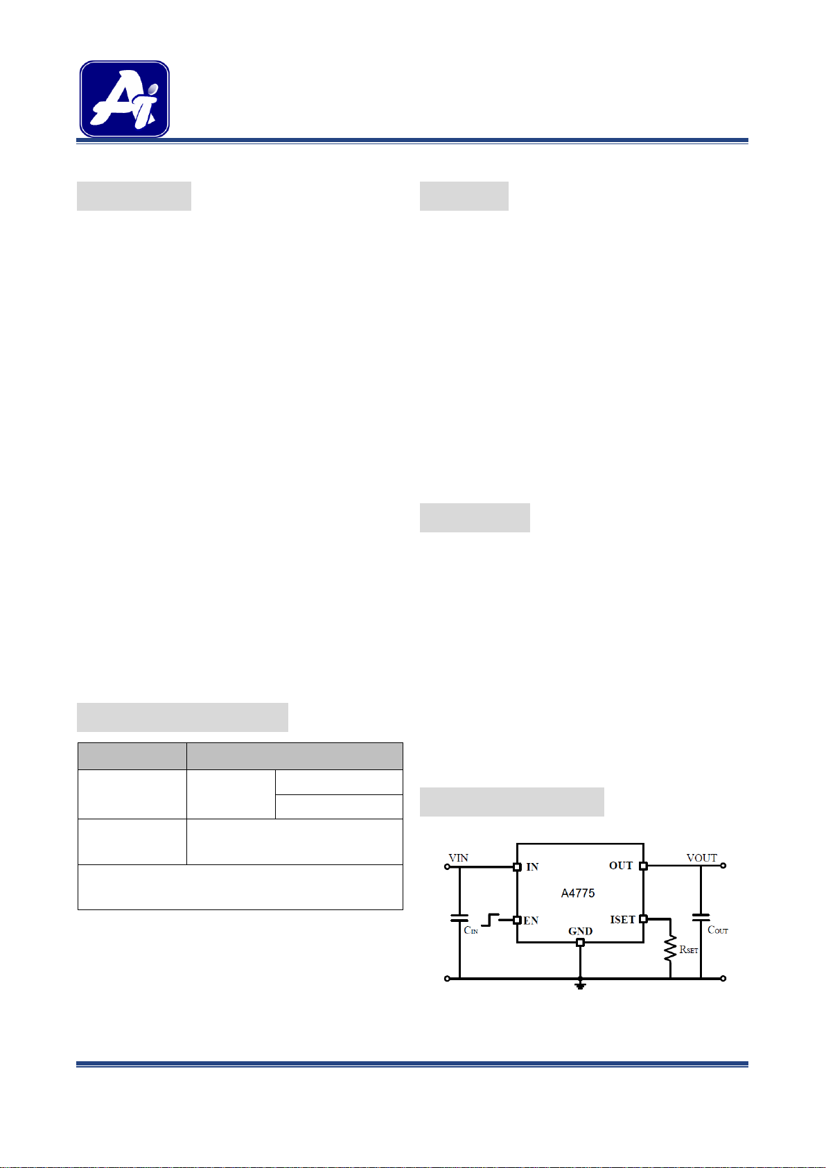
switch . In order to fit different application, an ISET
pin is offered for current limit point setting, a resistor
from ISET to ground sets the current limit for the
switch.
Additional features include soft-start to limit inrush
current during plug-in, thermal shutdown to prevent
catastrophic switch failure from high-current loads,
Output anti back irrigation Protection whether EN
pin is connected GND or VIN, under-voltage lockout
(UVLO) to ensure that the device remains off
unless there is a valid input voltage present, a
precision resistor-programmable output current limit
up to 3.5A. Besides, the lower quiescent current as
40μA making this device ideal for portable
battery-operated equipment.
The A4775 is available in SOT-25 package.
ORDERING INFORMATION
Package Type
Part Number
SOT-25
E5
A4775E5R
A4775E5VR
Note
V: Halogen free Package
R: Tape & Reel
AiT provides all RoHS products
Suffix “ V “ means Halogen free Package
Adjustable Current Limiting up to 3.5A
Built-In (Typically 70mΩ) N-MOSFET
Reverse Current Flow Blocking (no body diode)
Output Can Be Forced Higher than Input (Off or
On State)
Low Supply Current :
40μA Typical at Switch on State
Less than 1μA Typical at Switch Off State
Guaranteed Continuous Load Current : 2.1A
Wide Input Voltage Ranges : 2V to 5.5V
Hot Plug-In Application (Soft-Start)
1.7V Typical Under-Voltage Lockout (UVLO)
Thermal Shutdown Protection
Available in SOT-25 Package
APPLICATION
USB 3G Datacard
USB Dongle
MiniPCI Accessories
LCD Monitor, LCD-TV
USB Power Module for ADSL
Information Appliance and Set-Top Box
Battery-Powered Equipment
Hot-Plug Power Supplies
ACPI Power Distribution
PCI Bus Power Switching
Motherboard & Notebook PCs
PC Card Hot Swap Application
TYPICAL APPLICATION
REV1.1 - JUN 2014 RELEASED, JUN 2014 UPDATAED - - 1 -
Page 2
AiT Semiconductor Inc.
www.ait-ic.com
A4775
SWITCH
70mΩ, 3A SMART UNIVERSAL POWER SWITCH
PIN DESCRIPTION
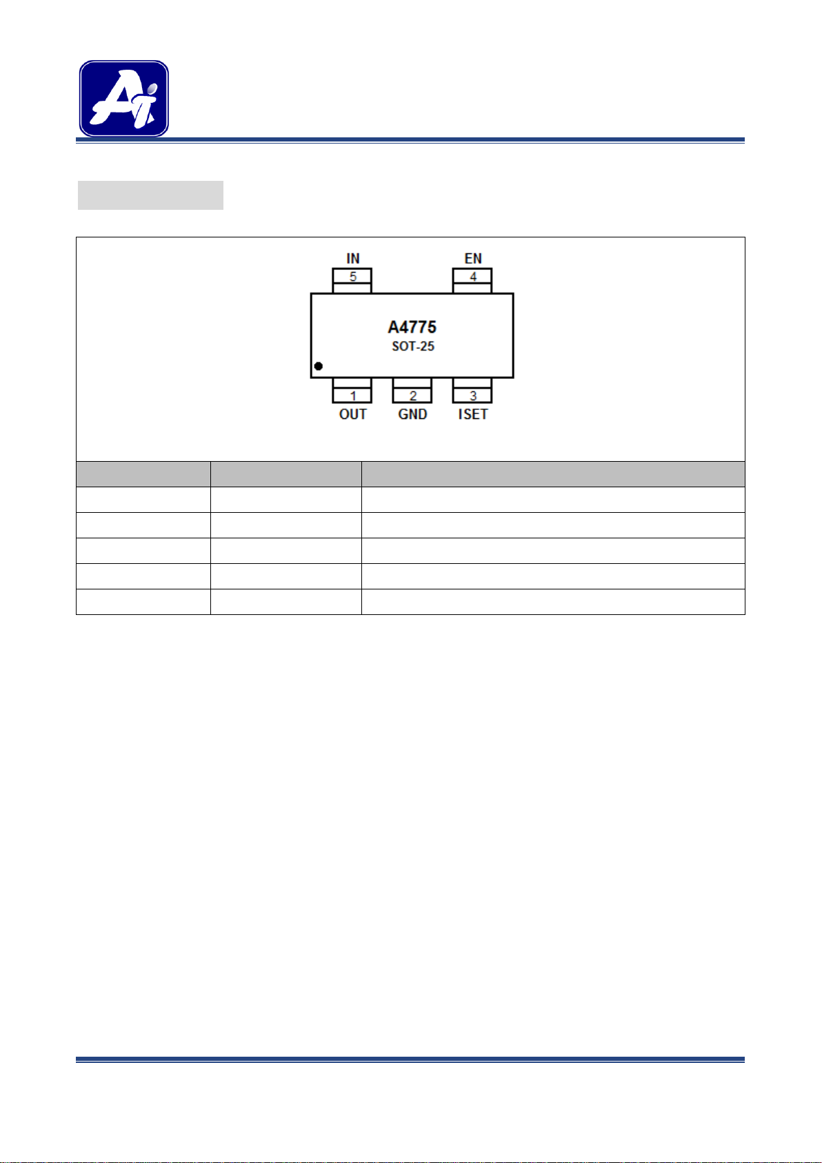
Top View
Pin #
Symbol
Function
1
OUT
Output Voltage.
2
GND
Ground. 3 ISET
Current Limit Programming Input.
4
EN
Chip Enable (Active High).
5
IN
Power Input Voltage.
REV1.1 - JUN 2014 RELEASED, JUN 2014 UPDATAED - - 2 -
Page 3
AiT Semiconductor Inc.
www.ait-ic.com
A4775
SWITCH
70mΩ, 3A SMART UNIVERSAL POWER SWITCH
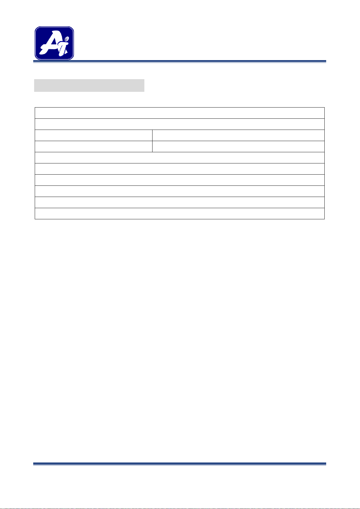
ABSOLUTE MAXIMUM RATINGS
Supply Voltage
6.5V
Chip Enable Input Voltage
-0.3V~6.5V
PD, Power Dissipation @ TA = 25°C
SOT-25
0.6W
Package Thermal Resistance
SOT-25
200°C/W
Junction Temperature
125℃
Lead Temperature (Soldering, 10 sec.)
260°C
Storage Temperature Range
-65°C ~150°C
ESD Susceptibility
HBM (Human Body Mode)
8kV
MM (Machine Mode)
800V
Stress beyond above listed “Absolute Maximum Ratings” may lead permanent damage to the device. These are stress ratings only and
operations of the device at these or any other conditions beyond those indicated in the operational sections of the specifications are not
implied. Exposure to absolute maximum rating conditions for extended periods may affect device reliability.
REV1.1 - JUN 2014 RELEASED, JUN 2014 UPDATAED - - 3 -
Page 4

AiT Semiconductor Inc.
www.ait-ic.com
A4775
SWITCH
70mΩ, 3A SMART UNIVERSAL POWER SWITCH
ELECTRICAL CHARACTERISTICS
Parameter
Symbol
Conditions
Min.
Typ.
Max.
Unit
Switch On Resistance
R
DS(ON)
I
OUT
= 1A
70
80
mΩ
Supply Current
I
SW_ON
Switch On, V
OUT
= Open
40
50
μA
Shutdown Current
I
SW_OFF
Switch Off, V
OUT
= Open
0.1 1 μA
CE Threshold Logic-Low Voltage
VIL
Switch Off
0.8
V
CE Threshold Logic-High Voltage
VIH
Switch On
2.0 V CE Input Current
ICE
VCE = 0V to 5.5V
10 pA
Output Leakage Current
I
LEAKAGE
VCE = 0V, R
LOAD
= 0Ω
0.5 μA
Output Turn-On Rise Time
T
ON_RISE
10% to 90% of V
OUT
rising
1.5 ms
Current Limit Factor
I
LIM
× R
SET
270k A·Ω
Max. Current Limit Setting
I
LIMSET
VIN=3.3V to 5.5V,
R
SET
=75kΩ
3.5
A
Current Limit Setting Accuracy
ΔI
LIMSET
I
LIMSET
= 0.5A to 3A
(R
SET
= 540kΩ to 90kΩ)
-20
+20
%
Under-Voltage Lockout
V
UVLO
VIN increasing
1.3
1.7 V
Under-Voltage Hysteresis
ΔV
UVLO
VIN decreasing
0.1 V
Thermal Shutdown Protection
TSD
120 ℃
Thermal Shutdown Hysteresis
ΔTSD
30 ℃
VS = +5V, VCM = +2.5V, VO = +2.5V, TA = +25℃, unless otherwise noted.
REV1.1 - JUN 2014 RELEASED, JUN 2014 UPDATAED - - 4 -
Page 5

AiT Semiconductor Inc.
www.ait-ic.com
A4775
SWITCH
70mΩ, 3A SMART UNIVERSAL POWER SWITCH
TEST CIRCUIT
REV1.1 - JUN 2014 RELEASED, JUN 2014 UPDATAED - - 5 -
Page 6

AiT Semiconductor Inc.
www.ait-ic.com
A4775
SWITCH
70mΩ, 3A SMART UNIVERSAL POWER SWITCH
PACKAGE INFORMATION
Symbol
Min
Max
A
1.050
1.250
A1
0.000
0.100
A2
1.050
1.150
b
0.300
0.400
c
0.100
0.200
D
2.820
3.020
E
1.500
1.700
E1
2.650
2.950
e
0.950(TYP)
e1
1.800
2.000 L 0.700(REF)
L1
0.300
0.600
θ
0°
8°
Dimension in SOT-25 (Unit: mm)
REV1.1 - JUN 2014 RELEASED, JUN 2014 UPDATAED - - 6 -
Page 7

AiT Semiconductor Inc.
www.ait-ic.com
A4775
SWITCH
70mΩ, 3A SMART UNIVERSAL POWER SWITCH
IMPORTANT NOTICE
AiT Semiconductor Inc. (AiT) reserves the right to make changes to any its product, specifications, to
discontinue any integrated circuit product or service without notice, and advises its customers to obtain the
latest version of relevant information to verify, before placing orders, that the information being relied on is
current.
AiT Semiconductor Inc.'s integrated circuit products are not designed, intended, authorized, or warranted to
be suitable for use in life support applications, devices or systems or other critical applications. Use of AiT
products in such applications is understood to be fully at the risk of the customer. As used herein may involve
potential risks of death, personal injury, or servere property, or environmental damage. In order to minimize
risks associated with the customer's applications, the customer should provide adequate design and
operating safeguards.
AiT Semiconductor Inc. assumes to no liability to customer product design or application support. AiT
warrants the performance of its products of the specifications applicable at the time of sale.
REV1.1 - JUN 2014 RELEASED, JUN 2014 UPDATAED - - 7 -
Page 8

 Loading...