

Page 1
Data Sheet
March 2001
A370-Type Analog
Uncooled Laser Module
Applications
■
Narrowband video
■
Downstream telephony and data
■
Return path systems
■
Analog and digital modulation systems
■
Telecommunications
The low-profile A370-Type Analog Laser Module is ideally
suited for CATV applications, particularly in systems where
long spans and superior reliability are the critical considerations
.
Features
■
Eight-pin package suitable for CATV
applications
Frequency range up to 1.0 GHz
■
MQW F-P 1.3 µ m laser with single-mode fiber
■
pigtail
■
Wide operating temperature range:
–40 ° C to +85 ° C
No TEC required
■
High output power: typically 1.0 mW power cou-
■
pled into single-mode fiber
■
Hermetically sealed active components
Internal back-facet monitor
■
Qualification program:
■
TA-983
Telcordia Technologies
*
Benefits
■
Easily board mounted
■
Requires no lead bending
■
No additional heat sinks required
■
Pin compatible with industry-standard, 14-pin
laser module
■
High output power allows for longer system spans ,
more fiber splits, and greater tolerance of fiber and
connector quality
*
T elcordia T echnologies
Inc.
is a trademark of Telcordia Technologies,
Page 2
±
°
°
A370-Type Analog Data Sheet
Uncooled Laser Module March 2001
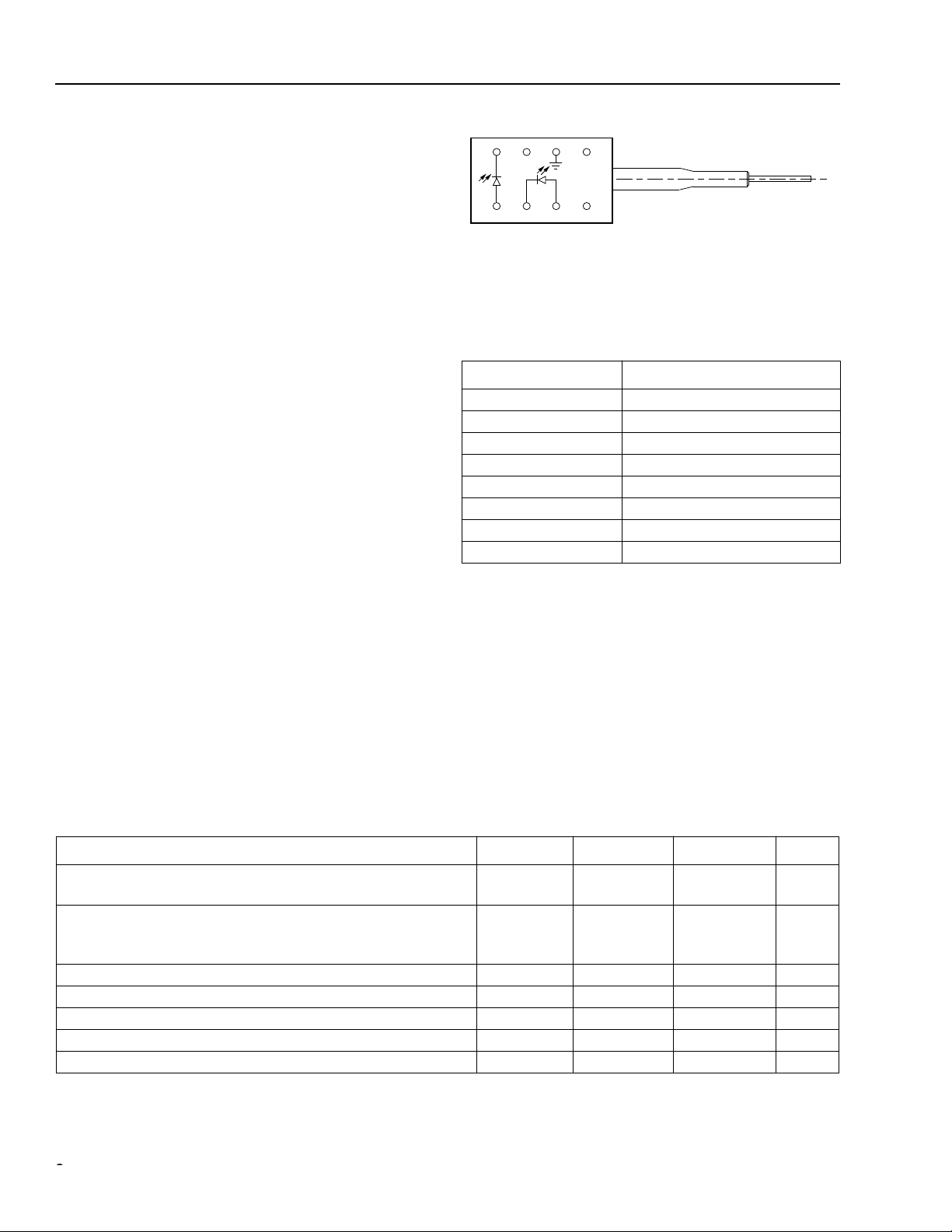
Description
The A370-Type Uncooled Laser Module consists of a
laser diode coupled to a single-mode fiber pigtail. The
device is available in a standard, 8-pin configuration
(see Figure 1 and/or Table 1) and is ideal for CATV
applications.
The module includes a multiquantum-well Fabry-Perot
(MQW F-P) laser and an InGaAs PIN photodiode backfacet monitor in an epoxy-free, hermetically sealed
package.
The device characteristics listed in this document are
met at 1.0 mW output power. Higher- or lower-power
operation is possible. Under conditions of a fixed photodiode current, the change in optical output is typically
0.5 dB over an operating temperature range of –40 ° C
to +85 ° C.
This device incorporates the new Laser 2000 manufac-
turing process from the Optoelectronics unit of Lucent
Technologies Microelectronics Group. Laser 2000 is a
low-cost platform that targets high-volume manufacturing and tight product distributions on all optical subassemblies. This platform incorporates an advanced
optical design that is produced on the Optoelectronic
unit’s highly automated production lines. The Laser
2000 platform is qualified for the central office and
uncontrolled environments, and can be used for applications requiring high performance and low cost.
43 12
56 87
Figure 1. A370-Type Analog Uncooled Laser
Module Schematic, Top View
Table 1. Pin Descriptions
Pin Number Connection
1NC
2 Case ground
3NC
4 Photodiode cathode
5 Photodiode anode
6 Laser diode cathode
7 Laser diode anode
8NC
1-900 (C)
Absolute Maximum Ratings
Stresses in excess of the absolute maximum ratings can cause permanent damage to the device. These are absolute stress ratings only. Functional operation of the device is not implied at these or any other conditions in excess
of those given in the operations sections of the data sheet. Exposure to absolute maximum ratings for extended
periods can adversely affect device reliability.
Parameter Symbol Min Max Unit
Maximum Peak Laser Drive Current or
Maximum Fiber Power*
Peak Reverse Laser Voltage:
Laser
Monitor
Monitor Forward Current I
Operating Case Temperature Range T
Storage Case Temperature Range T
Lead Soldering Temperature/Time — — 260/10 ° C/s
Relative Humidity (noncondensing) RH — 85 %
* Rating varies with temperature.
22
OP
I
MAX
P
RL
V
RD
V
FD
C
stg
—
—
—
—
150
10
2
20
mA
mW
V
V
—2mA
–40 85
–40 85
C
C
Lucent Technologies Inc.
Page 3

°
∆λ
±
Ω
µ
Data Sheet A370-Type Analog
March 2001 Uncooled Laser Module
Handling Precautions
Caution: This device is susceptible to dama ge as a result of electrostatic disc harge (ESD). T ake pr oper pre-
cautions during both handling and testing. Follow guidelines such as JEDEC Publication No.
108-A (Dec. 1988).
Although protection circuitry is designed into the device, take proper precautions to avoid exposure to ESD.
Electro/Optical Characteristics
Table 2. Electro/Optical Characteristics (over operating temperature range unless otherwise noted)
Parameter Symbol Test Conditions Min Typ Max Unit
Operating Temperature
Range
Optical Output Power* P
Threshold Current I
Drive Current Above
Threshold
Slope Efficiency SE CW, P
Center Wav elength
RMS Spectral Width
Tracking Error TE I
Forward Voltage V
Input Impedance R — 3 — 8
Monitor Current I
Monitor Dark Current I
Wavelength Temperature
Coefficient
* See Table 5 for more information.
† V
= reverse voltage.
R
T — –40 — 85
CW, nominal — 1 — mW
T = 25 ° C
T = full range
F
= 1.0 mW, T = 25 ° C
MON
CW, I
= constant,
4.5
1
20
15
9
—
30
—
TH
MOD
I
F
CW, P
15
45
40
70
C
mA
mA
mA
mA
T = full range
λ
C
F
MON
D
= 1.0 mW, T = 25 ° C25—50
F
P
= 1.0 mW, CW 1270 — 1350 nm
F
P
= 1.0 mW — 2 3 nm
F
= constant, CW — 0.5
MON
CW — 1.1 1.6 V
†
V
= 5 V 400 — 1200
R
†
V
= 5 V — 10 200 nA
R
µ
W/mA
1dB
— — — 0.4 0.5 nm/ ° C
A
Lucent Technologies Inc.
3
Page 4

A370-Type Analog Data Sheet
Uncooled Laser Module March 2001
Electro/Optical Characteristics
(continued)
Analog Operation
The A370 Series Laser Module has the capability of being used in a wide variety of analog operations. These may
include several channels of pure video signals , or a mix of video signals with digital data channels riding on analog
carriers. It is difficult to prepare a single battery of testing conditions that will satisfy all applications. The following
table contains a set of testing conditions that Lucent believes will give a broad indication of the performance of the
A370 Series Laser Module. Please contact your local Field Application Engineer if different testing conditions and
parametric limits are required.
The distortion characteristics are measured using a two-tone test. The frequencies are 13 MHz and 19 MHz. The
second-order distortion components are measured at f1 + f2 = 32 MHz and f1 – f2 = 6 MHz. All third-order distortion components are measured in the frequency range of 5 MHz—200 MHz, and they meet the required level. All
measurements are made with SC-SPC connectors on the laser module pigtails.
Table 3. Analog Characteristics
Parameter Symbol Test Conditions Min Typ Max Unit
Output Power* P
Relative Intensity Noise RIN CW,
Modulation Bandwidth BW –3 dB,
Second-order Distortions — T = 25 ° C, OMI = 0.2;
Third-order Distortions — T = 25 ° C, OMI = 0.2;
RF Bandpass Flatness B
Spurious Noise N
Spurious Noise (carrier off) N'
* See Table 5 for more information.
†Premium performance.
O
CW, T = –40 ° C to +85 ° C — 1.0 — mW
— –140 –130 dB/Hz
Freq. = 5 MHz to 300 MHz;
no fiber loss, T = –40 ° C to +85 ° C
1.0 — — GHz
T = –40 ° C to +85 ° C
Two-tone test: f1 = 13 MHz,
— –48
–50
–40
†
–45
†
f2 = 19 MHz; 20 km of fiber,
(7 dB loss) plus connector loss,
f1 ± f2
Two-tone test: f1 = 13 MHz,
— –60
–60
–50
†
–50
†
f2 = 19 MHz; 20 km of fiber
(7 dB loss), plus connector loss,
all peaks from 5 MHz—50 MHz
meet this level
F Peak to valley: 5 MHz to 200 MHz — — 1.0 dB
P
SP
T = 25 ° C, OMI = 0.2;
ref. to one-tone: 5 MHz to 50 MHz,
— –58
–58
–54
†
–54
†
20 km of fiber, (7 dB loss) plus
connector loss
SP
T = 25 ° C — –45
–45
–37
†
–40
†
dBc
dBc
dBc
dBc
dBc
dBc
dBc
dBc
4
Lucent Technologies Inc.
Page 5

(
)
Data Sheet A370-Type Analog
March 2001 Uncooled Laser Module
Outline Diagram
Dimensions are in inches and (millimeters).
TRADEMARK, CODE, LASER SERIAL NUMBER,
AND/OR DATE CODE IN APPROXIMATE AREA SHOWN
3
4
5678
21
0.52 (13.2)
1.06 (27.0)
MIN
39.37 (1000) MIN
PIGTAIL LENGTH
0.20 (5.00)
0.165 (4.20)
0.100 (2.54)
0.300
(7.62)
0.045 (1.143)
0.016 (0.410)
0.110 (2.79)
0.010
(0.254)
0.29
(7.37)
0.17
(4.32)
0.30
7.62
0.085
(2.16)
1-899.f
Lucent Technologies Inc.
5
Page 6

A370-Type Analog Data Sheet
Uncooled Laser Module March 2001
Qualification Information
The A370-Type Laser Module has passed the following qualification tests and meets the intent of
nologies
Table 4. A371-Type Laser Module Qualification Test Plan
Mechanical Shock
Vibration
Solderability
Thermal Shock
Fiber Pull
Accelerated (Biased) Aging
High-temperature Storage
Temperature Cycling
Cyclic Moisture Resistance
Damp Heat
Internal Moisture
Flammability
ESD Threshold
TR-NWT-000468 for interoffice environments and TA-TSY-000983 for outside plant environments.
Qualification Test Conditions Sample Size Reference
500 G
20 g, 20 Hz—2,000 Hz
—
Delta T = 100 ° C
1 kg; 3 times
85 °C, 5,000 hrs.
85 °C, 2,000 hrs.
500 cycles
10 cycles
40 °C, 95% RH,
1,344 hrs.
<5,000 ppm water vapor
—
—
11 MIL-STD-883
Method 2002
11 MIL-STD-883
Method 2007
11 MIL-STD-883
Method 2007
11 MIL-STD-883
Method 2003
11
25
11
11
11
11 MIL-STD-202
11 MIL-STD-883
— TR357
6
Telcordia Technologies
Telcordia Technologies
Section 5.18
Telcordia Technologies
Telcordia Technologies
Section 5.20
Telcordia Technologies
Section 5.23
Method 103
Method 1018
Sec. 4.4.2.5
Telcordia Technologies
Section 5.22
Telcordia Tech-
983
983
983
983
983
983
6
Lucent Technologies Inc.
Page 7

Data Sheet A370-Type Analog
March 2001 Uncooled Laser Module
Laser Safety Information
Class IIIb Laser Product
FDA/CDRH Class IIIb laser product. All versions are Class IIIb laser products per CDRH, 21 CFR 1040 Laser
Safety requirements. All versions are Class 3B laser products per
fied with the FDA under accession number 8720010.
This product complies with 21 CFR 1040.10 and 1040.11.
8.3 µm single-mode pigtail or connector
Wavelength = 1.3 µm
Maximum power = 10 mW
Because of size constraints, laser safety labeling is not affixed to the module but attached to the outside of the
shipping carton.
Product is not shipped with power supply.
Caution: Use of controls, adjustments, and procedures other than those specified herein may result in
hazardous laser radiation exposure.
IEC
* 60825-1:1993. The device has been classi-
DANGER
INVISIBLE LASER RADIATION
IS EMITTED FROM THE END
OF FIBER OR CONNECTOR
Avoid direct exposure to beam
Do not view beam directly with
optical instruments
INVISIBLE LASER RADIATION EMITTED FROM END OF FIBER OR CONNECTOR
Avoid exposure to beam
Class 3B Laser Product IEC-60825M 1993 Max. Output: 10 mW Wavelength: 1.3 µm
*
IEC
is a registered trademark of The International Electrotechnical Commission.
Lucent Technologies Inc.
7
Page 8

A370-Type Analog Data Sheet
Uncooled Laser Module March 2001
Ordering Information
Table 5. Ordering Information
Code Comcode Pfiber Connector
Performance
Option
A370-10A 108009150 1.0 mW SC-PC Standard
A370-10F 108013954 1.0 mW FC-PC Standard
A370-10B 108024183 1.0 mW SC-APC Standard
A370-10G 108061839 1.0 mW FC-APC Standard
A370-10N 108013962 1.0 mW none Standard
A370-11A 108225384 1.0 mW SC-PC Premium
A370-11F 108225392 1.0 mW FC-PC Premium
For additional information, contact your Microelectronics Group Account Manager or the following:
INTERNET: http://www.lucent.com/micro, or for Optoelectronics information, http://www.lucent.com/micro/opto
E-MAIL: docmaster@micro.lucent.com
N. AMERICA: Microelectronics Group, Lucent Technologies Inc., 555 Union Boulevard, Room 30L-15P-BA, Allentown, PA 18109-3286
ASIA PACIFIC: Microelectronics Group, Lucent Technologies Singapore Pte. Ltd., 77 Science Park Drive, #03-18 Cintech III, Singapore 118256
CHINA: Microelectronics Group, Lucent Technologies (China) Co., Ltd., A-F2, 23/F, Zao Fong Universe Building, 1800 Zhong Shan Xi Road,
JAPAN: Microelectronics Group, Lucent Technologies Japan Ltd., 7-18, Higashi-Gotanda 2-chome, Shinagawa-ku, Tokyo 141, Japan
EUROPE: Data Requests: MICROELECTRONICS GROUP DATALINE: Tel. (44) 7000 582 368, FAX (44) 1189 328 148
Lucent Technologies Inc. reserves the right to make changes to the product(s) or information contained herein without notice. No liability is assumed as a result of their use or application. No
rights under any patent accompany the sale of any such product(s) or information.
Copyright © 2001 Lucent Technologies Inc.
All Rights Reserved
March 2001
DS99-034LWP-1 (Replaces DS99-034LWP)
1-800-372-2447, FAX 610-712-4106 (In CANADA: 1-800-553-2448, FAX 610-712-4106)
Tel. (65) 778 8833, FAX (65) 777 7495
Shanghai 200233 P. R. China
Tel. (81) 3 5421 1600, FAX (81) 3 5421 1700
Technical Inquiries: OPTOELECTRONICS MARKETING: (44) 1344 865 900 (Ascot UK)
Tel. (86) 21 6440 0468, ext. 325, FAX (86) 21 6440 0652
 Loading...