

Datasheet A3518LUA-TL, A3518LUA, A3517SUA-TL, A3517SUA, A3517LUA-TL Datasheet (Allegro)
...Page 1
The A3517xUA and A3518xUA are sensitive, temperature-stable linear
Hall-effect sensors with greatly improved offset characteristics. Ratiometric,
linear Hall-effect sensors provide a voltage output that is proportional to the
applied magnetic field and have a quiescent output voltage that is approximately 50% of the supply voltage. These magnetic sensors are ideal for use in
linear and rotary position sensing systems in the harsh environments of
automotive and industrial applications over extended temperatures to -40°C
and +150°C. The A3517xUA features an output sensitivity of 5 mV/G while
the A3518xUA has an output sensitivity of 2.5 mV/G. See the Magnetic
Characteristics table for complete, individual device parametrics.
Each BiCMOS monolithic circuit integrates a Hall element, improved
temperature-compensating circuitry to reduce the intrinsic sensitivity drift of
the Hall element, a small-signal high-gain amplifier, and a rail-to-rail lowimpedance output stage.
A proprietary dynamic offset cancelation technique, with an internal highfrequency clock, reduces the residual offset voltage, which is normally caused
by device overmolding, temperature dependancies, and thermal stress. This
technique produces devices that have an extremely stable quiescent output
voltage, are immune to mechanical stress, and have precise recoverability after
temperature cycling. Many problems normally associated with low-level
analog signals are minimized by having the Hall element and amplifier in a
single chip. Output precision is obtained by internal gain and offset trim
adjustments during the manufacturing process.
These reduced-cost devices are supplied in a 3-pin ultra-mini-SIP “UA”
package only.
FEATURES
■ Temperature-Stable Quiescent Output Voltage
■ Precise Recoverability After Temperature Cycling
■ Output Voltage Proportional to Applied Magnetic Field
■ Ratiometric Rail-to-Rail Output
■ Improved Sensitivity
■ 4.5 V to 5.5 V Operation
■ Immune to Mechanical Stress
■ Small Package Size
■ Solid-State Reliability
Always order by complete part number, e.g., A3517SUA .
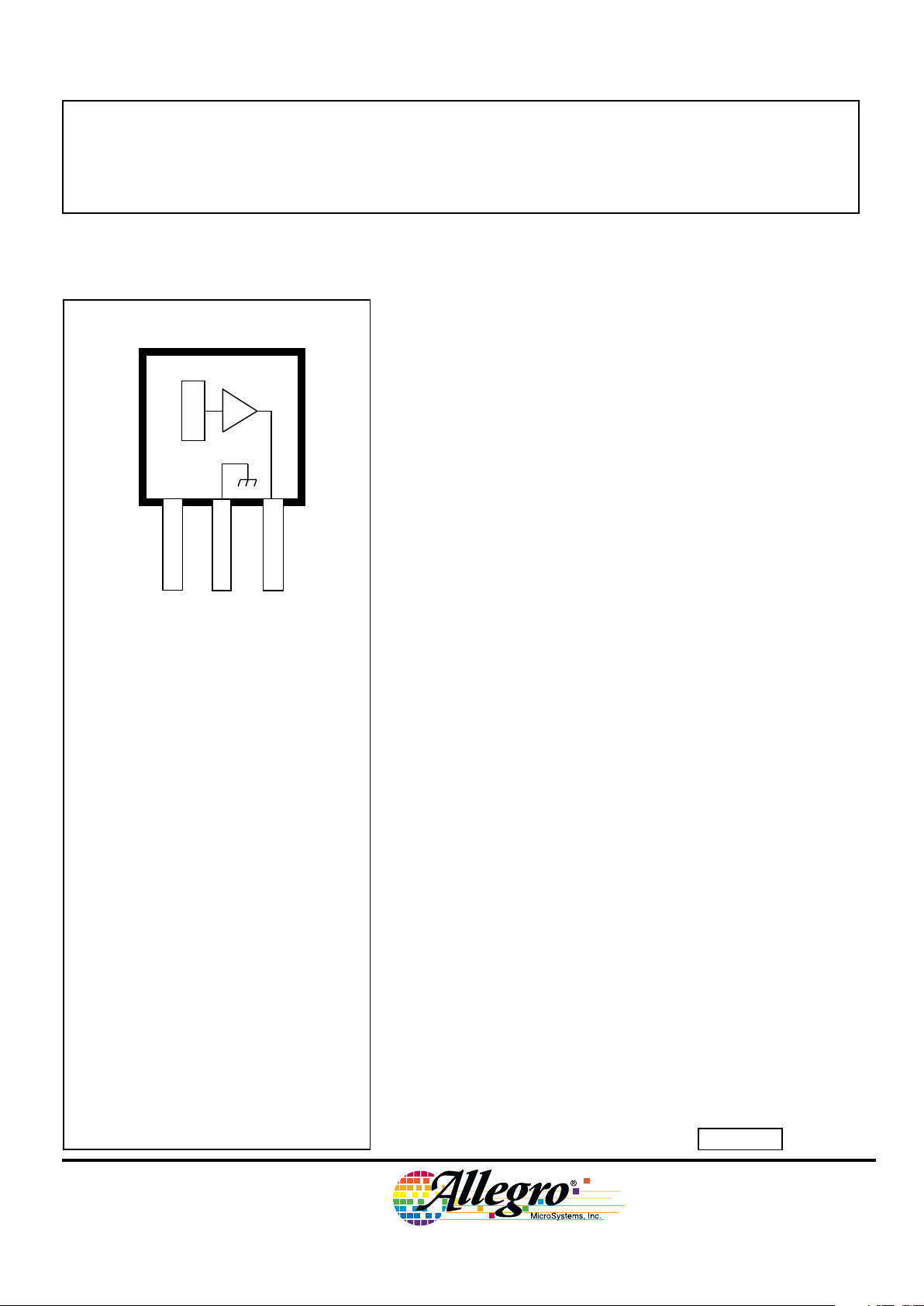
RATIOMETRIC, LINEAR HALL-EFFECT SENSORS
FOR HIGH-TEMPERATURE OPERATION
Dwg. PH-006
1
SUPPLY
V
CC
GROUND
32
OUTPUT
X
Data Sheet
27501.11§
Pinning is shown viewed from branded side.
ABSOLUTE MAXIMUM RATINGS
Supply Voltage, VCC......................... 8.0 V
Output Voltage, VO........................... 8.0 V
Output Sink Current, IO.................. 10 mA
Magnetic Flux Density, B ......... Unlimited
Package Power Dissipation,
PD.................................... See Graph
Operating Temperature Range*, T
A
Suffix S– .................... -20°C to +85°C
Suffix L–....................-40°C to +150°C
Storage Temperature Range,
TS............................. -65°C to +170°C
* Infrequent excursions permitted; see
Applications Information.
3517
AND
3518
Page 2
3517
AND
3518
RATIOMETRIC,
LINEAR HALL-EFFECT SENSORS
FOR HIGH-TEMP. OPERATION
115 Northeast Cutoff, Box 15036
Worcester, Massachusetts 01615-0036 (508) 853-5000
2
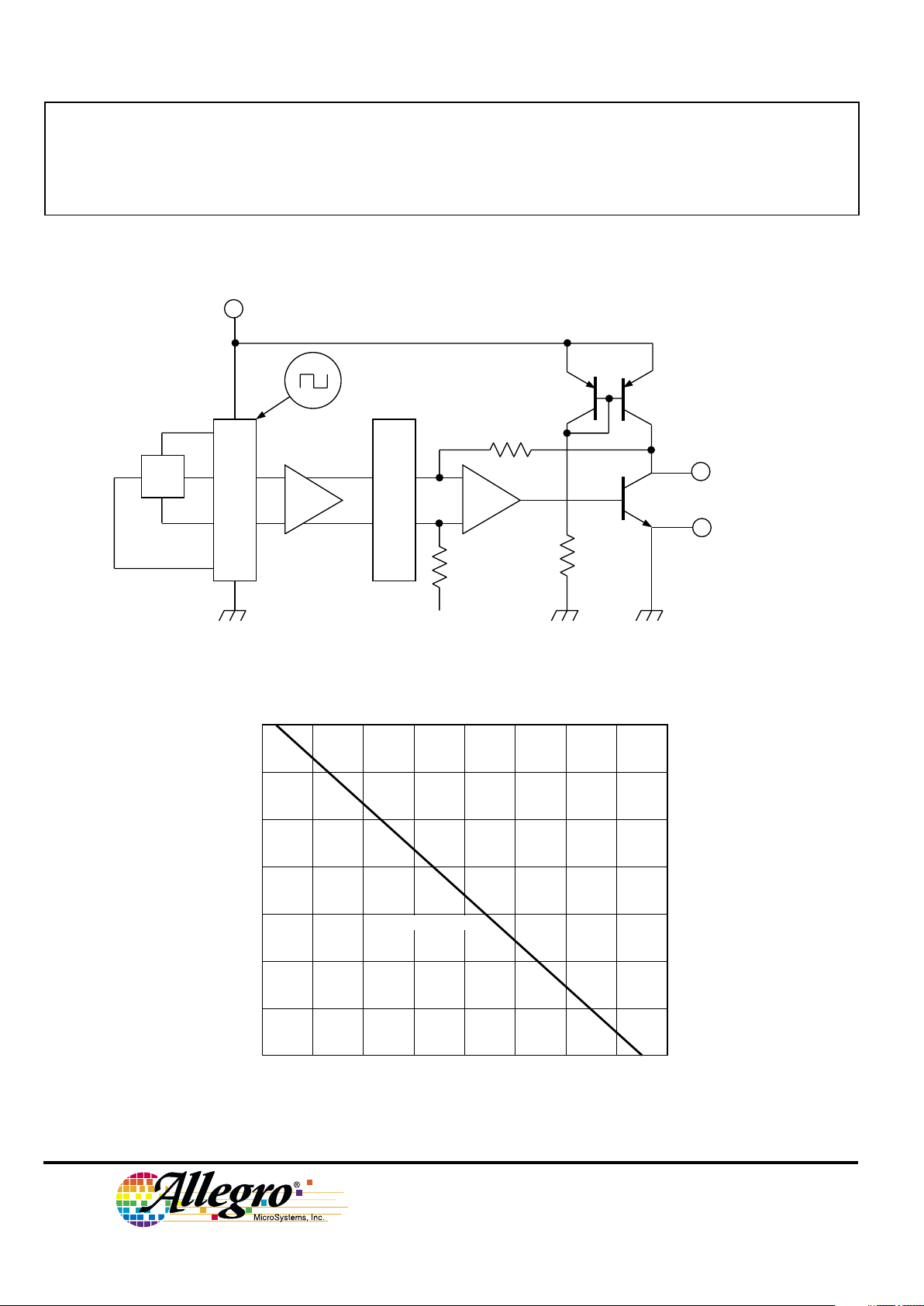
FUNCTIONAL BLOCK DIAGRAM
Dwg. FH-016A
GROUND
2
OUTPUT
3
1
X
DYNAMIC
OFFSET CANCELLATION
LOW-PASS
FILTER
–
+
–
+
SUPPLY
Vcc
Vcc/2
600
400
200
20 60 100
140
0
AMBIENT TEMPERATURE in °C
ALLOWABLE PACKAGE POWER DISSIPATION in MILLIWATTS
Dwg. GH-046-1
R
θJA
= 206°C/W
40 80 120 180
700
500
300
100
160
Copyright © 1997, 2000 Allegro MicroSystems, Inc.
Page 3
3517
AND
3518
RATIOMETRIC,
LINEAR HALL-EFFECT SENSORS
FOR HIGH-TEMP. OPERATION
www.allegromicro.com
3
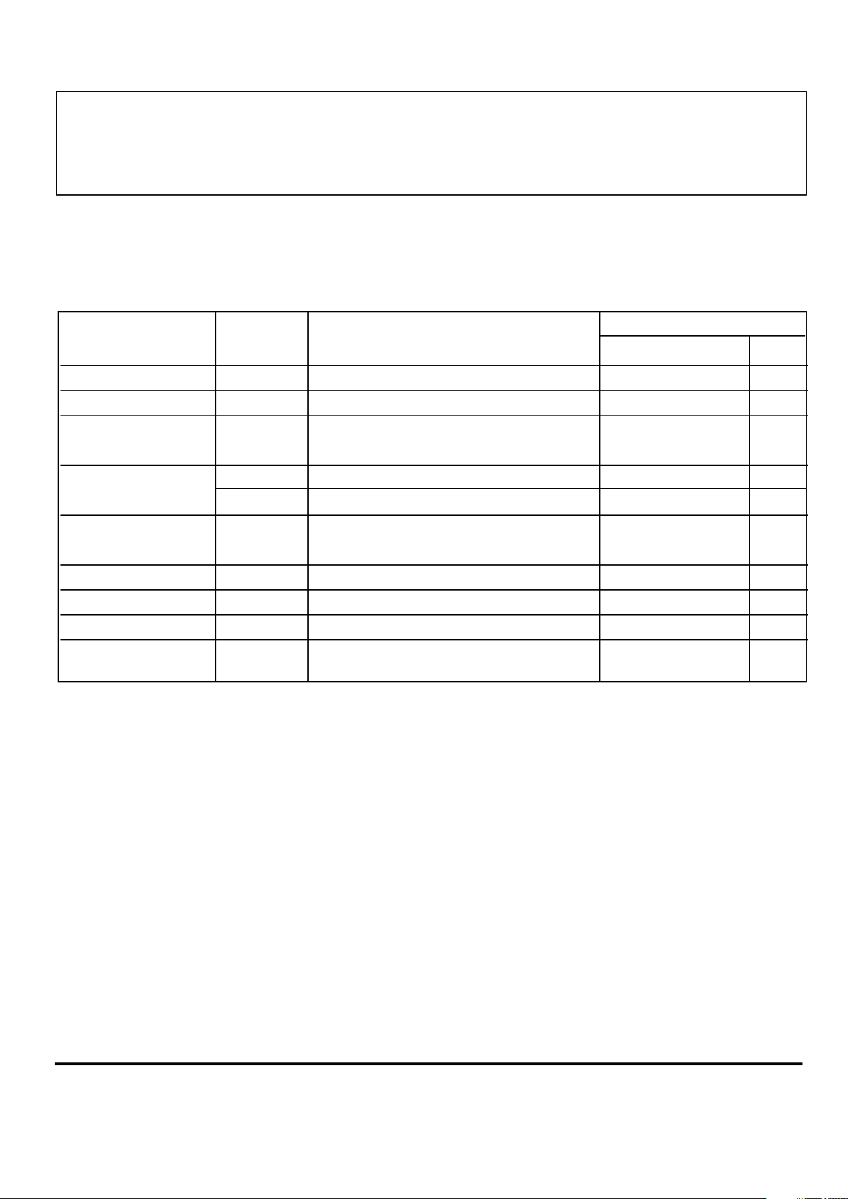
ELECTRICAL CHARACTERISTICS over operating temperature range, at VCC = 5 V (unless
otherwise noted).
Limits
Characteristic Symbol Test Conditions Min. Typ. Max. Units
Supply Voltage V
CC
Operating 4.5 5.0 5.5 V
Supply Current I
CC
B = 0, VCC = 6 V, IO = 0 – 7.2 12 mA
Quiescent V
OQ
B = 0, IO = 1 mA, TA = 25°C 2.2 2.5 2.8 V
Voltage Output
Output Voltage V
OH
B = +X*, IO = 1 mA – 4.7 – V
V
OL
B = -X*, IO = -1 mA – 0.2 – V
Output I
OLM
B = -X*, VO = 0 -1.0 -1.5 – mA
Source Current Limit
Bandwidth (-3 dB) BW – 30 – kHz
Clock Frequency f
C
– 170 – kHz
Output Resistance r
O
IO ≤ -2 mA – 1.0 – Ω
Wide-Band e
o
B = 0, BW = 10 Hz to 10 kHz, – 400 – µV
Output Noise (rms) IO ≤ -1 mA, CO = 100 pF
NOTE 1 – Typical data is at TA = 25°C and is for design information only.
NOTE 2 – Negative current is defined as coming out of (sourcing) the output.
* This test requires positive and negative fields sufficient to swing the output driver between fully OFF and saturated (ON),
respectively. It is NOT intended to indicate a range of linear operation.
Page 4
3517
AND
3518
RATIOMETRIC,
LINEAR HALL-EFFECT SENSORS
FOR HIGH-TEMP. OPERATION
115 Northeast Cutoff, Box 15036
Worcester, Massachusetts 01615-0036 (508) 853-5000
4
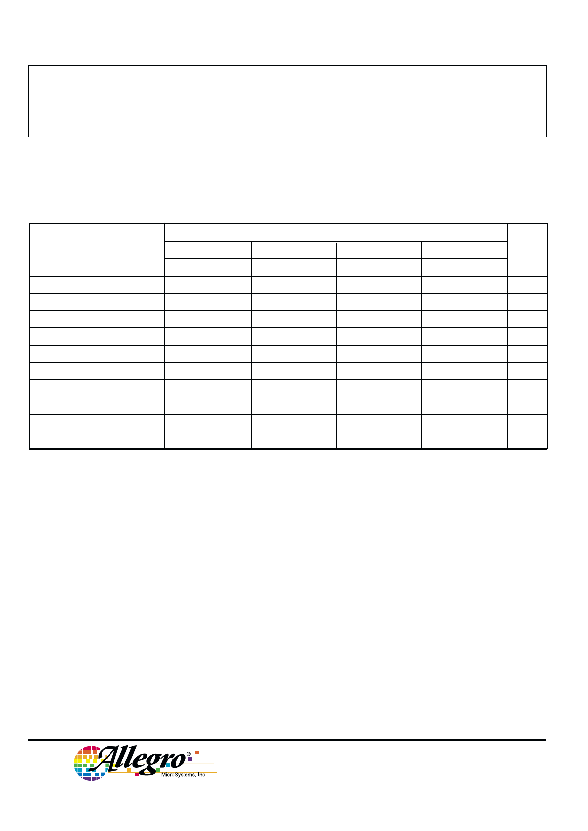
MAGNETIC CHARACTERISTICS over operating temperature range, at VCC = 5 V, IO = -1 mA
(unless otherwise noted).
Part Numbers
A3517SUA A3517LUA A3518SUA A3518LUA
Characteristic* Min. Typ. Max. Min. Typ. Max. Min. Typ. Max. Min. Typ. Max. Units
Operating Temp. Range, T
A
-20 – +85 -40 – +150 -20 – +85 -40 – +150 °C
Sensitivity at TA = 25°C 4.0 5.0 6.0 4.0 5.0 6.0 2.0 2.5 3.0 2.0 2.5 3.0 mV/G
∆Sens
(∆T)
at TA = Max. -5.0 2.5 10 -5.0 2.5 10 -5.0 2.5 10 -5.0 2.5 10 %
∆Sens
(∆T)
at TA = Min. -9.0 -1.3 6.0 -9.0 -1.3 6.0 -9.0 -1.3 6.0 -9.0 -1.3 6.0 %
∆V
OQ(∆T)
†
––±20 ––±20 ––±20 ––±20 G
Ratiometry, ∆V
OQ(∆V)
– 100 ––100 ––100 ––100 – %
Ratiometry, ∆Sens
(∆V)
– 100 ––100 ––100 ––100 – %
Positive Linearity, Lin+ – 100 ––100 ––100 ––100 – %
Negative Linearity, Lin––100 ––100 ––100 ––100 – %
Symmetry – 100 ––100 ––100 ––100 – %
NOTE 1 – Magnetic flux density is measured at most sensitive area of device located 0.018" (0.46 mm) below the
branded face of the package.
NOTE 2 – 10 G = 1 mT, exactly.
NOTE 3 – Except for ∆Sens
(∆T)
, typical data is at TA = 25°C and is for design information only.
* See Characteristics Definitions for test conditions.
† This calculation (formula 1, next page) yields the device’s equivalent accuracy, over the operating temperature range, in
gauss.
Page 5

3517
AND
3518
RATIOMETRIC,
LINEAR HALL-EFFECT SENSORS
FOR HIGH-TEMP. OPERATION
www.allegromicro.com
5
CHARACTERISTICS DEFINITIONS
Ratiometry. The A3517xUA and A3518xUA feature a
ratiometric output. The quiescent voltage output and
sensitivity are proportional to the supply voltage
(ratiometric).
The per cent ratiometric change in the quiescent
voltage output is defined as
∆V
OQ(∆V)
=
V
OQ(VCC)
/ V
OQ(5V)
x 100% (4)
VCC / 5 V
and the per cent ratiometric change in sensitivity is defined
as
∆Sens
(∆V)
=
Sens
(VCC)
/ Sens
(5V)
x 100% (5)
VCC / 5 V
Linearity and Symmetry. The on-chip output stage is
designed to provide a linear output to within 500 mV of
either rail with a supply voltage of 5 V. This is equivalent
to approximately ±800 gauss of ambient field. Although
application of stronger magnetic fields will not damage
these devices, it will force the output into a non-linear
region. Linearity in per cent is measured and defined as
Lin+ =
V
O(500G)
– VOQ
x 100% (6)
2 (V
O(250G)
– VOQ)
Lin– =
V
O(-500G)
– VOQ
x 100% (7)
2 (V
O(-250G)
– VOQ)
and output symmetry as
Sym =
V
O(500G)
– VOQ
x 100% (8)
VOQ – V
O(-500G)
Quiescent Voltage Output. In the quiescent state (no
magnetic field), the output is ideally equal to one-half of
the supply voltage over the operating voltage and temperature range (VOQ ≈ VCC/2). Due to internal component
tolerances and thermal considerations, there is a tolerance
on the quiescent voltage output and on the quiescent
voltage output as a function of supply voltage and ambient
temperature. For purposes of specification, the quiescent
voltage output as a function of temperature is defined as
∆V
OQ(∆T)
=
V
OQ(TA)
– V
OQ(25°C)
(1)
Sens
(25°C)
This calculation yields the device’s equivalent
accuracy, over the operating temperature range, in gauss.
Sensitivity. The presence of a south-pole magnetic field
perpendicular to the package face (the branded surface)
will increase the output voltage from its quiescent value
toward the supply voltage rail by an amount proportional to
the magnetic field applied. Conversely, the application of
a north pole will decrease the output voltage from its
quiescent value. This proportionality is specified as the
sensitivity of the device and is defined as
Sens =
V
O(500G)
– V
O(-500G)
(2)
1000 G
The stability of sensitivity as a function of tempera-
ture is defined as
∆Sens
(∆T)
=
Sens
(TA)
– Sens
(25°C)
x 100% (3)
Sens
(25°C)
Page 6

3517
AND
3518
RATIOMETRIC,
LINEAR HALL-EFFECT SENSORS
FOR HIGH-TEMP. OPERATION
115 Northeast Cutoff, Box 15036
Worcester, Massachusetts 01615-0036 (508) 853-5000
6
TYPICAL CHARACTERISTICS
0 25 50 75
100
AMBIENT TEMPERATURE IN °C
-50
Dwg. GH-039-2
125
-25
SUPPLY CURRENT IN mA
9.0
8.0
7.0
6.0
150
Vcc = 5.5 V
0 25 50 75
100
1.4
0.4
AMBIENT TEMPERATURE IN °C
1.2
0.8
-50
Dwg. GH-060-1
OUTPUT RESISTANCE IN Ω
150
-25
125
1.0
0.6
Vcc = 5 V
I
O
=
-1
m
A
I
O
=
1
m
A
I
O
= 5 mA
I
O
= 10 m
A
0 25 50 75
100
AMBIENT TEMPERATURE IN °C
2.55
2.45
-50
Dwg. GH-067-1
QUIESCENT OUTPUT VOLTAGE IN VOLTS
150
-25
125
2.50
Vcc = 5 V
Io = -1 mA
A3518–
A3517–
2.46
2.47
2.48
2.49
2.51
2.52
2.53
2.54
0 25 50 75
100
6.0
1.0
AMBIENT TEMPERATURE IN °C
5.0
3.0
-50
Dwg. GH-066-1
SENSITIVITY IN mV/G
150
-25
125
4.0
2.0
A3518–
A3517–
Vcc = 5 V
Io = -1 mA
0
Page 7

3517
AND
3518
RATIOMETRIC,
LINEAR HALL-EFFECT SENSORS
FOR HIGH-TEMP. OPERATION
www.allegromicro.com
7
Qualification Test Test Method and Test Conditions Test Length Samples Comments
Temperature Humidity JESD22-A101 1000 hrs 77 Device biased for
Bias Life TA = 85°C, RH = 85% minimum power
Bias Life JESD22-A108 1000 hrs 77
TA = 150°C, TJ = 165°C
(Surge Operating Life) JESD22-A108 168 hrs 77
TA = 175°C, TJ = 190°C
Autoclave, Unbiased JESD22-A102 96 hrs 77
TA = 121°C, 15 psig
High-Temperature JESD22-A103 1000 hrs 77
(Bake) Storage Life TA = 170°C
Temperature Cycle JESD22-A104 1000 cycles 77
ESD, CDF-AEC-Q100-002 Pre/Post 3 per Test to failure
Human Body Model Reading test All leads > 3 kV
All Allegro sensors are subjected to stringent qualification requirements prior to being released to production.
To become qualified, except for the destructive ESD tests, no failures are permitted.
CRITERIA FOR DEVICE QUALIFICATION
Page 8

3517
AND
3518
RATIOMETRIC,
LINEAR HALL-EFFECT SENSORS
FOR HIGH-TEMP. OPERATION
115 Northeast Cutoff, Box 15036
Worcester, Massachusetts 01615-0036 (508) 853-5000
8
APPLICATIONS INFORMATION
Calibrated linear Hall devices, which can be used to
determine the actual flux density presented to the sensor in a
particular application, are available.
For safe, reliable operation, the output should not be pulled
above the supply voltage or pulled below the device ground.
For optimum performance, a 0.1 µF capacitor between the
supply and ground, and a 100 pF capacitor between the output
and ground, should be added.
The ratiometric feature is especially valuable when these
devices are used with an analog-to-digital converter. A/D
converters typically derive their LSB step size by ratioing off a
reference voltage line. If the reference voltage varies, the LSB
will vary proportionally. This is a major error source in many
sensing systems. The A3517xUA and A3518xUA can eliminate
this source of error by their ratiometric operation. Because their
gain and offsets are proportional to the supply voltage, if they
are powered from the A/D reference voltage, the sensor output
voltage will track changes in the LSB value.
These devices can withstand infrequent temperature
excursions, beyond the Absolute Maximum Ratings, to
T
A
= 170°C provided the junction temperature, TJ, does not
exceed 200°C.
Extensive applications information on Hall-effect sensors
and magnets is also available in the “Hall-Effect IC Applications
Guide”, which can be found in the latest issue of the Allegro
MicroSystems Electronic Data Book, AMS-702 or Application
Note 27701, or at
www.allegromicro.com
TYPICAL CURRENT-SENSING APPLICATION
B ≈ N x 6.9 G/A
Dwg. AH-005A
1 32
Dwg. MH-011-7
0.018"
0.46 mm
NOM
BRANDED
SURFACE
ACTIVE AREA DEPTH
0.081"
2.06 mm
0.056"
1.42 mm
A
Allegro
SENSOR LOCATION
Page 9

3517
AND
3518
RATIOMETRIC,
LINEAR HALL-EFFECT SENSORS
FOR HIGH-TEMP. OPERATION
www.allegromicro.com
9
0
0
RELATIVE DISTANCE
RELATIVE MAGNETIC FLUX DENSITY
Dwg. GH-048
RELATIVE OUTPUT VOLTAGE
V
CC
V
OQ
-0.4 -0.2 0.2 0.4
+
GND
-
N S
D
0.19
0
0
RELATIVE DISTANCE (TOTAL EFFECTIVE AIR GAP)
RELATIVE MAGNETIC FLUX DENSITY
Dwg. GH-047
RELATIVE OUTPUT VOLTAGE
V
CC
V
OQ
N S
D
SENSOR DEPTH
BELOW PACKAGE FACE
0.1 0.2 0.3 0.4 0.5
+
0
0
RELATIVE DISTANCE
RELATIVE MAGNETIC FLUX DENSITY
Dwg. GH-050
RELATIVE OUTPUT VOLTAGE
V
CC
V
OQ
N S
0.05 0.10 0.15 0.20 0.25
+
D
EFFECTIVE
AIR GAP
0.21
EFFECTIVE AIR GAP = 0.050
EFFECTIVE AIR GAP = 0.075
EFFECTIVE AIR GAP = 0.095
0
0
RELATIVE DISTANCE
RELATIVE MAGNETIC FLUX DENSITY
Dwg. GH-049
RELATIVE OUTPUT VOLTAGE
V
CC
V
OQ
-0.06 -0.04 0.04 0.06 0.08
+
GND
-
-0.08
0.10
-0.10
N S
S N
N S
S N
D
0.21
D
0.19
S N
N S
TYPICAL POSITION-SENSING APPLICATIONS
(Alnico 8, dimensions in inches)
Page 10

3517
AND
3518
RATIOMETRIC,
LINEAR HALL-EFFECT SENSORS
FOR HIGH-TEMP. OPERATION
115 Northeast Cutoff, Box 15036
Worcester, Massachusetts 01615-0036 (508) 853-5000
10
Dwg. MH-014E in
0.164
0.159
0.062
0.058
0.0173
0.0138
0.050
BSC
45°
0.640
0.600
0.0189
0.0142
0.085
MAX
45°
0.031
123
0.122
0.117
SEE NOTE
Dwg. MH-014E mm
4.17
4.04
1.57
1.47
0.44
0.35
1.27
BSC
45°
16.26
15.24
0.48
0.36
2.16
MAX
45°
0.79
123
3.10
2.97
SEE NOTE
NOTES: 1. Tolerances on package height and width represent allowable mold offsets. Dimensions given are measured at the widest
point (parting line).
2. Exact body and lead configuration at vendor’s option within limits shown.
3. Height does not include mold gate flash.
4. Recommended minimum PWB hole diameter to clear transition area is 0.035” (0.89 mm).
5. Where no tolerance is specified, dimension is nominal.
6. Supplied in bulk pack (500 devices per bag).
Dimensions in Inches
(controlling dimensions)
Dimensions in Millimeters
(for reference only)
PACKAGE DESIGNATOR ‘UA’
Page 11

3517
AND
3518
RATIOMETRIC,
LINEAR HALL-EFFECT SENSORS
FOR HIGH-TEMP. OPERATION
www.allegromicro.com
11
The products described herein are manufactured under one or more
of the following U.S. patents: 5,045,920; 5,264,783; 5,442,283;
5,389,889; 5,581,179; 5,517,112; 5,619,137; 5,621,319; 5,650,719;
5,686,894; 5,694,038; 5,729,130; 5,917,320; and other patents
pending.
Allegro MicroSystems, Inc. reserves the right to make, from time to
time, such departures from the detail specifications as may be required
to permit improvements in the performance, reliability, or
manufacturability of its products. Before placing an order, the user is
cautioned to verify that the information being relied upon is current.
Allegro products are not authorized for use as critical components
in life-support appliances, devices, or systems without express written
approval.
The information included herein is believed to be accurate and
reliable. However, Allegro MicroSystems, Inc. assumes no responsibility for its use; nor for any infringements of patents or other rights of
third parties that may result from its use.
0.095
±0.005
0.020
MIN
FLAT
Dwg. MH-015 in
0.004
MAX
0.002
MAX
0°–8°
2.41
±0.13
0.51
MIN
FLAT
Dwg. MH-015 mm
0.10
MAX
0.051
MAX
0°–8°
Surface-Mount Lead Form (add ‘-TL’ to part number)
Dimensions in Inches
(controlling dimensions)
Dimensions in Millimeters
(for reference only)
NOTE: Supplied in bulk pack (500 devices per bag).
Page 12

3517
AND
3518
RATIOMETRIC,
LINEAR HALL-EFFECT SENSORS
FOR HIGH-TEMP. OPERATION
115 Northeast Cutoff, Box 15036
Worcester, Massachusetts 01615-0036 (508) 853-5000
12
HALL-EFFECT SENSORS
Partial Part Avail. Oper. Characteristics at TA = +25°C
Number Temp. B
OP
max B
RP
min B
hys
typ Features Notes
RATIOMETRIC, LINEAR HALL-EFFECT SENSORS
3503 S typ. 1.3 mV/G
3507 E/L typ. 2.5 mV/G
3508 S typ. 2.5 mV/G
3515 E/L typ. 5.0 mV/G chopper stabilized
3516 E/L typ. 2.5 mV/G chopper stabilized
3517 L/S typ. 5.0 mV/G chopper stabilized
3518 L/S typ. 2.5 mV/G chopper stabilized
GEARTOOTH/RING MAGNET (DUAL ELEMENT) HALL-EFFECT SENSORS in order of B
OP
3060 K/S +35 -35 30 ac coupled
3422 E/L +75 -75 46 direction detection
3059 K/S +100 -100 130 ac coupled
3056 E/L +150 -150 50 zero-speed
3058 E/L +250 -250 200 zero-speed
3421 E/L +280 -280 335 direction detection
SPECIAL-PURPOSE HALL-EFFECT SENSORS
3054 K/S +300 +5.0 50 unipolar switch, multiplexed 4
3209 E ±60 ±5.0 7.7 400 µW, chopper stabilized
3210 E ±60 ±5.0 7.7 25 µW, chopper stabilized
3421 E/L +280 -280 335 direction detection
3422 E/L +85 -85 46 direction detection
3425 L +24 -24 19 dual, chopper stabilized 1
Operating Temperature Ranges:
S = -20°C to +85°C, E = -40°C to +85°C, J = -40°C to +115°C, K = -40°C to +125°C, L = -40°C to +150°C
Notes 1. Protected.
4. Multiplexed two-wire sensor; after proper address, power/signal bus current indicates magnetic field condition.
 Loading...