

Page 1
The A3421xKA and A3422xKA Hall-effect, direction-detection
sensors are a new generation of special-function integrated sensors that
are capable of sensing the direction of rotation of a ring magnet. These
transducers provide separate digital outputs that provide information on
magnet rotation speed, direction, and magnet pole count. These devices
eliminate the major manufacturing hurdles encountered in fine-pitch
direction-detection applications, namely maintaining accurate mechanical location between the two active Hall elements. Here, the two Hall
elements are photolithographically aligned to better than 1 µm, as
contrasted with 100 µm or worse mechanical location tolerance when
manufactured discretely. These highly sensitive, temperature-stable,
magnetic transducers are ideal for use in digital-encoder systems in the
harsh environments of automotive or industrial applications. The
A3421xKA is a high-hysteresis device designed for low-resolution
pulse counting while the A3422xKA is a high-sensitivity device
optimized for use with high-density magnets.
The A3421xKA and A3422xKA monolithic integrated circuits
contain two independent Hall-effect latches whose digital outputs are
internally coupled to CMOS logic circuitry that decodes signal speed
and direction. Extremely low-drift BiCMOS circuitry is used for the
amplifiers to ensure symmetry between the two latches so that signal
quadrature can be maintained. An on-chip voltage regulator allows the
use of these devices from a 4.5 V to 18 V supply. Both devices have
standard open-collector outputs; the logic operation of both devices is
the same.
Two operating temperature ranges are provided; suffix ‘E–’ is for
the automotive and industrial temperature range of -40°C to +85°C,
suffix ‘L–’ is for the automotive and military temperature range of
-40°C to +150°C. The 5-pin ‘KA’ SIP package provides a cost-competitive solution to linear magnetic sensing in harsh environments.
FEATURES
■ Internal Direction-Decoding Circuitry
■ Two Matched Hall Latches On A Single Substrate
■ Superior Temperature Stability
■ 4.5 V to 18 V Operation
Electrically Defined Power-On State
Under-Voltage Lockout
HALL-EFFECT,
DIRECTION-DETECTION SENSORS
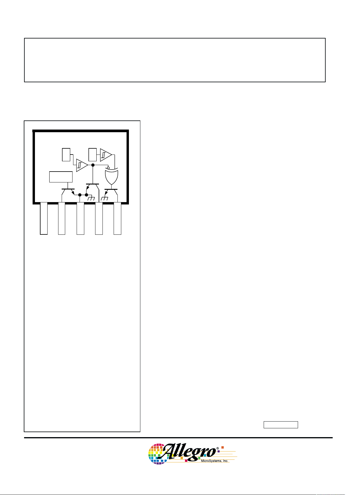
Always order by complete part number, e.g., A3421EKA .
X
V
CC
1 432 5
Dwg. PH-015
SUPPLY
DIRECTION
GROUND
E1 OUTPUT
SPEED
LOGIC
X
E1 E2
Pinning is shown viewed from branded side.
ABSOLUTE MAXIMUM RATINGS
Supply Voltage, VCC. . . . . . . . . . . . . 18 V
Magnetic Flux Density, B . . . . Unlimited
Output OFF Voltage, V
OUT
. . . . . . . . V
CC
Output Sink Current, I
OUT
. . . . . . . 30 mA
Package Power Dissipation,
PD. . . . . . . . . . . . . . . . . . . . . . 500 mW
Operating Temperature Range, T
A
Suffix ‘EKA’ . . . . . . . -40˚C to +85˚C
Suffix ‘LKA’ . . . . . . -40˚C to +150˚C
Storage Temperature Range,
TS. . . . . . . . . . . . . . . -65˚C to +170˚C
3421
AND
3422
PRELIMINARY INFORMATION
(subject to change without notice)
September 6, 2000
Data Sheet
27650.1
Page 2
3421
AND
3422
HALL-EFFECT,
DIRECTION-DETECTION
SENSORS
115 Northeast Cutoff, Box 15036
Worcester, Massachusetts 01615-0036 (508) 853-5000
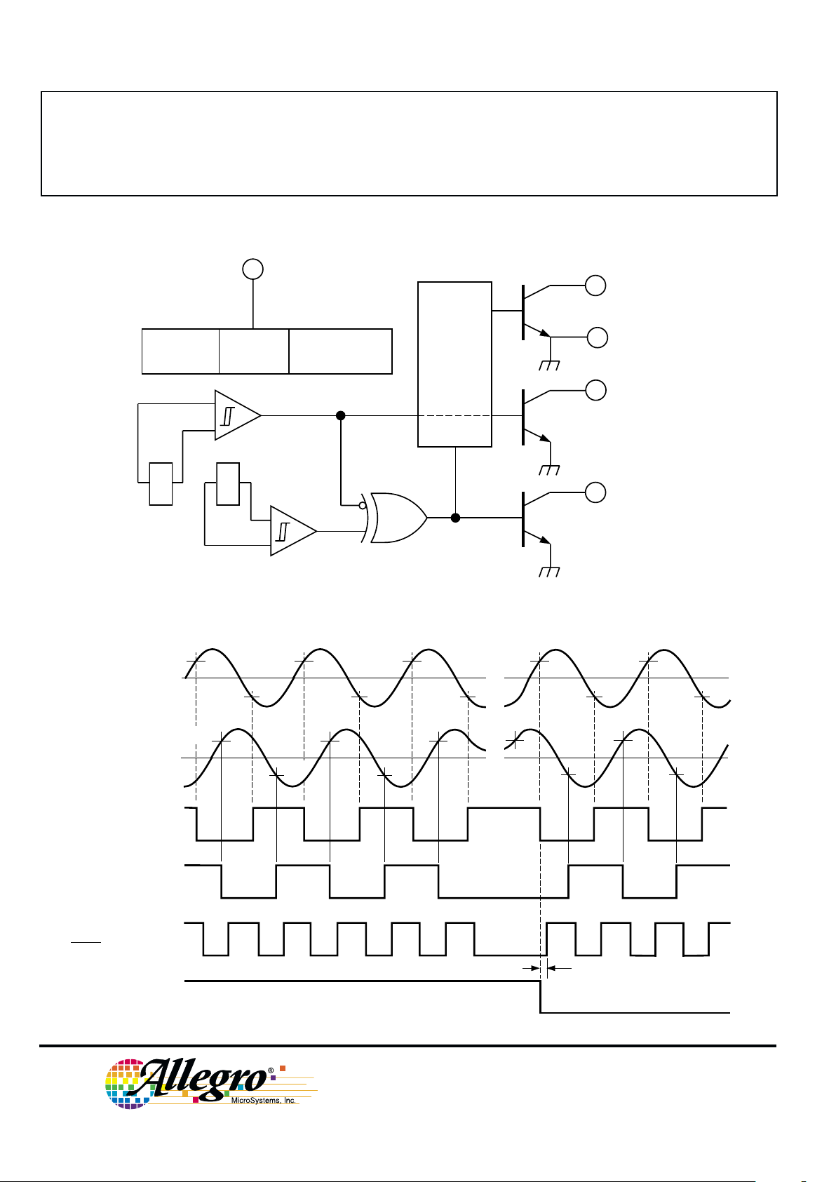
FUNCTIONAL BLOCK DIAGRAM
TIMING DIAGRAM
B
OP1
B
RP1
Dwg. WH-012A
0
+B
-B
0
+B
-B
B
RP2
OUT
E1
OUT
E2
(INTERNAL)
SPEED
(OUT
E1
XOR OUTE2)
B
OP2
DIRECTION
CHANGE IN DIRECTION
t
d
SPEED
4
DIRECTION2
E1 OUTPUT
1
X X
Dwg. FH-018
GROUND
5
3
LOGIC
E1
E2
SUPPLY
POWER-ON
LOGIC
REG
UVLO
Copyright © 1999 Allegro MicroSystems, Inc.
Page 3
3421
AND
3422
HALL-EFFECT,
DIRECTION-DETECTION
SENSORS
www.allegromicro.com
Limits
Characteristic Symbol Test Conditions Min. Typ. Max. Units
Supply Voltage Range V
CC
Operating, TJ < 165°C
1
4.5 — 18 V
Output Leakage Current I
OFF
V
OUT
= VCC = 18 V — <1.0 10 µA
Output Saturation Voltage V
OUT(SAT)IOUT
= 20 mA — 0.21 0.50 V
Power-On State POS VCC = 0 → 5 V, OFF OFF OFF —
B
RP1
< B < B
OP1
, B
RP2
< B < B
OP2
Under-Voltage Lockout V
CC(UV)IOUT
= 20 mA, VCC = 0 → 5 V — 3.5 — V
Under-Voltage Hysteresis V
CC(hys)
Lockout (V
CC(UV)
) - Shutdown — 0.5 — V
Power-On Time t
po
VCC > 4.5 V — — 50 µs
Output Rise Time t
r
CL = 20 pF, RL = 820 Ω — 200 — ns
Output Fall Time t
f
CL = 20 pF, RL = 820 Ω — 200 — ns
Direction Change Delay t
d
CL = 20 pF, RL = 820 Ω 0.5 1.0 5.0 µs
Supply Current I
CC
VCC = 8 V, All outputs OFF 5.0 9.0 18 mA
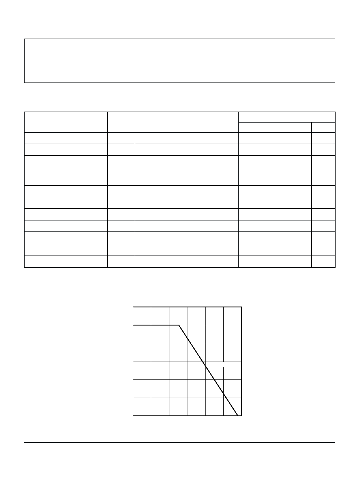
ELECTRICAL CHARACTERISTICS over operating temperature range.
50 75 100 125 175
0.5
0.1
0
ALLOWABLE PACKAGE POWER DISSIPATION IN WATTS
TEMPERATURE IN °C
0.4
0.3
0.2
25
Dwg. GH-069
R
θJA
= 164°C/W
0.6
150
NOTES:1. Maximum supply voltage must be adjusted for power dissipation and ambient temperature.
2. Typical Data is at VCC = 12 V and TA = +25°C and is for design information only.
Page 4

3421
AND
3422
HALL-EFFECT,
DIRECTION-DETECTION
SENSORS
115 Northeast Cutoff, Box 15036
Worcester, Massachusetts 01615-0036 (508) 853-5000
A3421xKA A3422xKA
Characteristic Symbol Test Conditions Min. Typ. Max. Min. Typ. Max. Units
Operate Point B
OP
TA = -40°C 140 185 300 — 29 85 G
TA = +25°C 130 160 280 — 29 75 G
TA = Maximum 120 — 260 — — 75 G
Release Point
3
B
RP
TA = -40°C -300 -190 -140 -85 -19 — G
TA = +25°C -280 -175 -130 -75 -18 — G
TA = Maximum -260 — -120 -75 -16 — G
Hysteresis B
hys
TA = -40°C 280 375 — 10 48 — G
TA = +25°C 260 335 — 10 46 — G
TA = Maximum 240 — — 10 — — G
Operate Differential B
OP1
- B
OP2
——±80 — — ±60 G
Release Differential B
RP1
- B
RP2
——±80 — — ±60 G
MAGNETIC CHARACTERISTICS over operating voltage range.
NOTES:1. Magnetic flux density is measured at most sensitive area of device,
nominally located 0.014” (0.37 mm) below the branded face of the package.
2. Typical Data is at VCC = 12 V and TA = +25°C and is for design information only.
3. As used here, negative flux densities are defined as less than zero (algebraic convention).
Page 5

3421
AND
3422
HALL-EFFECT,
DIRECTION-DETECTION
SENSORS
www.allegromicro.com
TYPICAL A3421xKA CHARACTERISTICS
TYPICAL A3422xKA CHARACTERISTICS
0 50 100
AMBIENT TEMPERATURE IN °C
-50
Dwg. GH-026-1
SWITCH POINTS IN GAUSS
0
10
OPERATE POINT
RELEASE POINT
150-25 25 75 125
20
30
40
50
-50
-40
-30
-20
-10
V = 8 V
CC
0 25 50 75
100
AMBIENT TEMPERATURE IN °C
-50
Dwg. GH-051-1
125-25
HYSTERESIS IN GAUSS
20
0
150
80
100
60
40
V = 8 V
CC
0 50 100
AMBIENT TEMPERATURE IN °C
-50
Dwg. GH-026-2
SWITCH POINTS IN GAUSS
0
50
OPERATE POINT
RELEASE POINT
150-25 25 75 125
100
150
200
250
-250
-200
-150
-100
-50
V = 8 V
CC
0 25 50 75
100
AMBIENT TEMPERATURE IN °C
-50
Dwg. GH-051-2
125-25
HYSTERESIS IN GAUSS
100
0
150
400
500
300
200
V = 8 V
CC
Page 6

3421
AND
3422
HALL-EFFECT,
DIRECTION-DETECTION
SENSORS
115 Northeast Cutoff, Box 15036
Worcester, Massachusetts 01615-0036 (508) 853-5000
TYPICAL ELECTRICAL CHARACTERISTICS
0 25 50 75
100
AMBIENT TEMPERATURE IN °C
-50
Dwg. GH-053-1
125-25
SUPPLY CURRENT IN mA
10
9.0
8.0
7.0
6.0
150
V = 8 V
CC
ALL OUTPUTS ON
ALL OUTPUTS OFF
0 25 50 75
100
300
0
AMBIENT TEMPERATURE IN °C
200
100
-50
Dwg. GH-029-2
SATURATION VOLTAGE IN mV
150
-25
125
I = 20 mA
OUT
250
150
50
12
SUPPLY VOLTAGE IN VOLTS
10
8.0
6.0
Dwg. GH-058-3
SUPPLY CURRENT IN mA
11
9.0
7.0
13
5.0
ALL OUTPUTS ON
ALL OUTPUTS OFF
2.0 6.0 10 14 18
T = 25°C
A
Page 7

3421
AND
3422
HALL-EFFECT,
DIRECTION-DETECTION
SENSORS
www.allegromicro.com
Outputs. The device provides three saturated outputs:
DIRECTION, E1 OUTPUT, and SPEED. DIRECTION
provides the direction output of the sensor and is defined
as OFF (high) for the direction E1 to E2 and ON (low) for
the direction E2 to E1. SPEED provides an XOR’d output
of the two sensors. Because of internal delays, DIRECTION will always be updated before SPEED and is
updated at every transition of E1 OUTPUT and E2 OUTPUT (internal) allowing the use of up-down counters
without the loss of pulses.
Power-On State. At power on, the logic circutry is reset
to provide an OFF (high) at DIRECTION and an OFF
(high) for E1 and E2 (internal) for magnetic fields less
than B
OP
. This eliminates ambiguity when the device is
powered up and either sensor detects a field between B
OP
and BRP. If either sensor is subjected to a field greater than
B
OP
, the internal logic will set accordingly.
The integrated circuit contains an internal voltage regulator that powers the Hall sensors and both the analog and
digital circuitry. This regulator allows operation over a
wide supply voltage range and provides some immunity to
supply noise. The device also contains CMOS logic
circuitry that decodes the direction of rotation of the ring
magnet.
Quadrature/Direction Detection. Internal logic
circuitry provides outputs representing speed and direction
of the magnetic field across the face of the package. For
the direction signal to be appropriately updated, a quadrature relationship must be maintained between the ring
magnet pole width*, the sensor-to-sensor spacing, and, to a
lesser extent, the magnetic switch points. For optimal
design, the sensor should be actuated with a ring magnet
pole width* two times the sensor-to-sensor spacing. This
will produce a sinusoidal magnetic field whose period
(denoted as
Τ
) is then four times the sensor-to-sensor
spacing. A quadrature relationship can also be maintained
for a ring magnet that has a period that satisfies the relationship n
Τ
/4 = 1.5 mm, where n is any odd integer.
Therefore, ring magnets with pole-pair spacings equal to 6
mm (n = 1), 2 mm (n = 3), 1.2 mm (n = 5), etc. are permitted.
The response of the device to the magnetic field
produced by a rotating ring magnet is shown on page 2.
Note the phase shift between the two integrated sensors.
* “Pole” refers to a single pole (North or South) unless
stated as “pole pair” (North
and South).
FUNCTIONAL DESCRIPTION
Page 8

3421
AND
3422
HALL-EFFECT,
DIRECTION-DETECTION
SENSORS
115 Northeast Cutoff, Box 15036
Worcester, Massachusetts 01615-0036 (508) 853-5000
APPLICATIONS INFORMATION
Operation with Fine-Pitch Ring Magnets. For
targets with a circular pitch of less than 4 mm, a performance improvement can be observed by rotating the front
face of the sensor subassembly (see below). This sensor
rotation decreases the effective sensor-to-sensor spacing,
provided that the Hall elements are not rotated beyond the
width of the target.
Applications. It is strongly recommended that an
external 0.01 µF bypass capacitor be connected (in close
proximity to the Hall sensor) between the supply and
ground of the device to reduce both external noise and
noise generated by the internal logic.
The simplest form of magnet that will operate these
devices is a ring magnet. Other methods of operation,
such as linear magnets, are possible. Extensive applications information on magnets and Hall-effect sensors is
also available in the “Hsall-Effect IC Applications Guide”
which can be found in the latest issue of the Allegro
MicroSystems Electronic Data Book, AMS-702 or Application Note 27701, or at
www.allegromicro.com
Dwg. MH-024
α
TARGET FACE WIDTH, F
>1.50 SIN
α
(mm)
>0.059 SIN
α
(inch)
1.50 COS
α
(mm)
0.059 COS
α
(inch)
A
0.059"
1.50 mm
12 4 53
A
1
2
4
5
3
Rotated sensor for
fine-pitch ring
magnets
Page 9

3421
AND
3422
HALL-EFFECT,
DIRECTION-DETECTION
SENSORS
www.allegromicro.com
CRITERIA FOR DEVICE QUALIFICATION
All Allegro sensors are subjected to stringent qualification requirements prior to being released to production. To
become qualified, except for the destructive ESD tests, no failures are permitted.
Test Method and Samples
Qualification Test Test Conditions Test Length Per Lot Comments
Temperature Humidity JESD22-A101, 1000 hrs 77 Device biased for
Bias Life TA = 85°C, RH = 85% minimum power
Bias Life JESD22-A108, 1000 hrs 77
TA = 150°C, TJ = 165°C
(Surge Operating Life) JESD22-A108, 1000 hrs 77
TA = 175°C, TJ = 190°C
Autoclave, Unbiased JESD22-A102, 96 hrs 77
TA = 121°C, 15 psig
High-Temperature JESD22-A103, 1000 hrs 77
(Bake) Storage Life TA = 170°C
Temperature Cycle JESD22-A104 1000 cycles 77 -55°C to +150°C
ESD, CDF-AEC-Q100-002 Pre/Post 3 per Test to failure
Human Body Model Reading test All leads > 8 kV
SENSOR LOCATIONS
(±0.005” [0.13 mm] die placement)
A
E1 E2
Dwg. MH-007-1
0.014"
0.37 mm
NOM
BRANDED
SURFACE
ACTIVE AREA DEPTH
0.059"
1.50 mm
12 4 53
0.096"
2.44 mm
0.072"
1.83 mm
Page 10

3421
AND
3422
HALL-EFFECT,
DIRECTION-DETECTION
SENSORS
115 Northeast Cutoff, Box 15036
Worcester, Massachusetts 01615-0036 (508) 853-5000
PACKAGE DESIGNATOR 'KA'
Dimensions in Inches
(controlling dimensions)
Dimensions in Millimeters
(for reference only)
Dwg. MH-010H in
0.018
0.0173
0.0138
0.0189
0.0142
0.050
BSC
13452
0.063
0.059
45°
0.600
0.560
0.083
MAX
0.252
0.247
0.181
0.176
SEE NOTE
SURFACE-MOUNT LEAD FORM (add ‘-TL’ to part number)
2.41
±0.13
0.51
MIN
FLAT
Dwg. MH-015 mm
0.10
MAX
0.051
MAX
0°–8°
0.095
±0.005
0.020
MIN
FLAT
Dwg. MH-015 in
0.004
MAX
0.002
MAX
0°–8°
NOTES: 1. Tolerances on package height and width represent allowable mold offsets. Dimensions given are measured at the widest point (parting line).
2. Exact body and lead configuration at vendor’s option within limits shown.
3. Height does not include mold gate flash.
4. Recommended minimum PWB hole diameter to clear transition area is 0.035” (0.89 mm).
5. Where no tolerance is specified, dimension is nominal.
Dwg. MH-010H mm
0.46
0.44
0.35
0.48
0.36
1.27
BSC
13452
1.60
1.50
45°
15.24
14.23
2.11
MAX
6.40
6.27
4.60
4.47
SEE NOTE
Page 11

3421
AND
3422
HALL-EFFECT,
DIRECTION-DETECTION
SENSORS
www.allegromicro.com
HALL-EFFECT SENSORS
Partial Part Avail. Oper. Characteristics at TA = +25°C
Number Temp. BOP max BRP min B
hys
typ Features Notes
RATIOMETRIC, LINEAR HALL-EFFECT SENSORS
3503 S typ. 1.3 mV/G
3507 E/L typ. 2.5 mV/G
3508 S typ. 2.5 mV/G
3515 E/L typ. 5.0 mV/G chopper stabilized
3516 E/L typ. 2.5 mV/G chopper stabilized
3517 L/S typ. 5.0 mV/G chopper stabilized
3518 L/S typ. 2.5 mV/G chopper stabilized
GEARTOOTH/RING MAGNET (DUAL ELEMENT) HALL-EFFECT SENSORS in order of B
OP
3060 K/S +35 -35 30 ac coupled
3422 E/L +75 -75 46 direction detection
3059 K/S +100 -100 130 ac coupled
3056 E/L +150 -150 50 zero-speed
3058 E/L +250 -250 200 zero-speed
3421 E/L +280 -280 335 direction detection
SPECIAL-PURPOSE HALL-EFFECT SENSORS
3054 K/S +300 +5.0 50 unipolar switch, multiplexed 4
3209 E ±60 ±5.0 7.7 400 µW, chopper stabilized
3210 E ±60 ±5.0 7.7 25 µW, chopper stabilized
3421 E/L +280 -280 335 direction detection
3422 E/L +85 -85 46 direction detection
3425 L +24 -24 19 dual, chopper stabilized 1
Operating Temperature Ranges:
S = -20°C to +85°C, E = -40°C to +85°C, J = -40°C to +115°C, K = -40°C to +125°C, L = -40°C to +150°C
Notes 1. Protected.
4. Multiplexed two-wire sensor; after proper address, power/signal bus current indicates magnetic field condition.
Page 12

3421
AND
3422
HALL-EFFECT,
DIRECTION-DETECTION
SENSORS
115 Northeast Cutoff, Box 15036
Worcester, Massachusetts 01615-0036 (508) 853-5000
The products described herein are manufactured under one or more
of the following U.S. patents: 5,045,920; 5,264,783; 5,442,283;
5,389,889; 5,581,179; 5,517,112; 5,619,137; 5,621,319; 5,650,719;
5,686,894; 5,694,038; 5,729,130; 5,917,320; and other patents
pending.
Allegro MicroSystems, Inc. reserves the right to make, from time to
time, such departures from the detail specifications as may be required
to permit improvements in the performance, reliability, or
manufacturability of its products. Before placing an order, the user is
cautioned to verify that the information being relied upon is current.
Allegro products are not authorized for use as critical components
in life-support appliances, devices, or systems without express written
approval.
The information included herein is believed to be accurate and
reliable. However, Allegro MicroSystems, Inc. assumes no responsibility for its use; nor for any infringements of patents or other rights of
third parties that may result from its use.
 Loading...