

Page 1
LEADTEK GPS MODULE
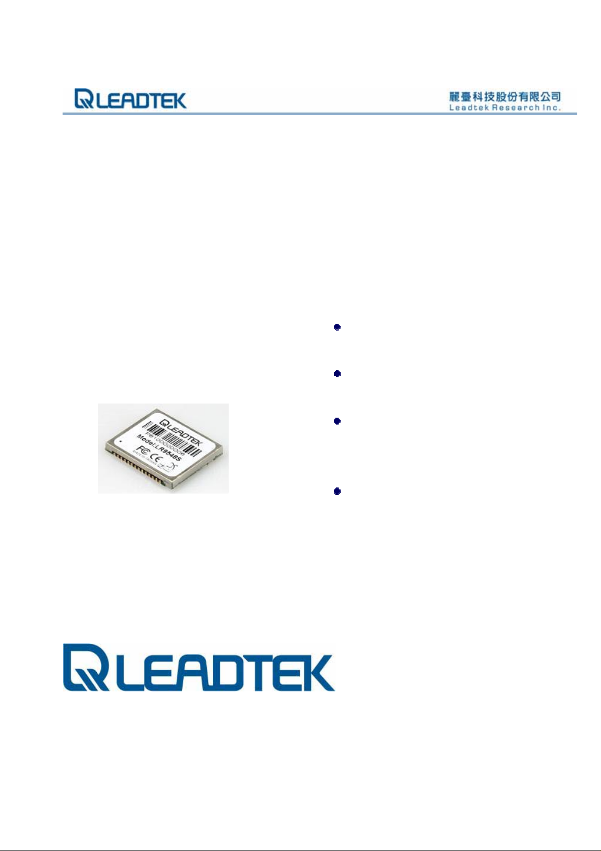
GPS 9548SLP
Specifications Sheet
Features:
SiRF StarIII low power
chipset
Compact module size for easy
integration : 24 x 20 x 2.9 mm
Multiple I/O pins reserved for
customizing special user
applications
RoHS compliance (lead-free)
ALL INFORMATION CONTAINED HEREIN IS THE SOLE PROPERTY OF LEADTEK RESEARCH AND CANNOT BE
DISSEMINATED WITHOUT THE EXPRESS WRITTEN CONSENT OF LEADTEK RESEARCH.
i
Page 2

LR9548SLP Specifications Sheet Rev. 0.1
Introduction
The Leadtek LR9548SLP GPS module is a high sensitivity, low power, Surface Mount Device (SMD).
This 20-channel global positioning system (GPS) receiver is designed for a wide range of OEM
applications and is based on the GPS signal search capabilities of the SiRFstarIII™ low power single
chipset, SiRF’s newest chipset technology. The LR9548SLP is also pin-to-pin compatible with the
LR9805-III (LR9548) for easier and faster transition.
The LR9548SLP is designed to allow quick and easy integration into GPS-related applications such
k
as:
e
t
t
e
PDA, Pocket PC, and other computing devices
d
Car and Marine Navigation
a
Fleet Management /Asset Tracking
AVL and Location-Based Services
Hand-Held Device for Personal Positioning and Navi gation
L
e
L
e
a
d
k
n
i
i
a
n
r
a
y
r
y
m
Features
l
l
e
Hardware and Software
Based on the high performance features of the SiRFstarIII low power single chipset
Compact module size for easy integration: 24x20x2.9 mm (0.94x0.79x0.11 in)
Fully automatic assembly: reflow solder assembly re ady
Hardware compatible with SiRF GSW3 v3.2.2 software
Multiple I/O pins reserved for customizing special user applications
RoHS compliance
Performance
Cold/Warm/Hot Start Time: 42/38/1 sec. at open sky and stationary environments.
Reacquisition Time: 0.1 second
RF Metal Shield for best performance in noisy environments
P
P
r
r
e
m
i
i
Multi-path Mitigation Hardware
© 2006 Leadtek Research Inc. All rights reserved. Page 1/11
Preliminary Confidential - Information is subject to change without prior notice.
Page 3

LR9548SLP Specifications Sheet Rev. 0.1
Interface
TTL level serial port for GPS communications interface
Protocol: NMEA-0183/SiRF Binary (default NMEA)
Baud Rate: 4800, 9600, 19200, 38400 or 57600 bps (default 4800)
Advantages
Ideal for high volume mass production(Taping reel package)
Cost saving through elimination of RF and board to board digital connectors
Flexible and cost effective hardware design for different application needs
e
Secure SMD PCB mounting method
d
a
L
P
P
e
L
e
r
r
a
e
e
l
l
d
t
t
m
m
i
i
k
e
i
i
k
n
n
a
a
r
r
y
y
© 2006 Leadtek Research Inc. All rights reserved. Page 2/11
Preliminary Confidential - Information is subject to change without prior notice.
Page 4
LR9548SLP Specifications Sheet Rev. 0.1
Specifications
Technical Specifications
Feature Item Description
Chipset
General
Accuracy
Datum
Time to First Fix
(TTFF)
(Open Sky &
Stationary
Requirements)
Dynamic
Conditions
Power
Serial Port
Time-1PPS
Pulse
L
L
P
P
GSC3f SiRFstarIII low power single chipset
Frequency L1, 1575.42 MHz
C/A code 1.023 MHz chip rate
Channels 20
Position
Velocity 0.1 meters/second
Time 1 microsecond synchronized to GPS time
Default WGS-84
Other selectable for other Datum
Reacquisition 0.1 sec., average
Snap start 1 sec., average
a
Hot start 1 sec., average typical TTFF
e
e
Warm start 38 sec., average typical TTFF
Cold start 42 sec., average typical TTFF
Altitude 18,000 meters (60,000 feet) max.
Velocity 515 meters/second (1000 knots) max.
Acceleration 4g, max.
Jerk 20 meters/second3, max.
Main power input 3.3 ~ 5.0 VDC input
Power consumption
r
r
Supply Current
Backup Power 1.65 ~ 5.0 VDC input.
Electrical interface Two full duplex serial TTL interface.
Protocol messages NMEA-0183@4800 bps (Default)
Level TTL
Pulse duration The 1PPS pulse width is 1 µs, this 1PPS is
Time reference At the pulse positive edge.
Measurement
a
e
e
d
d
l
l
10 meters, 2D RMS
5 meters 2D RMS, WAAS corrected
<5meters(50%)
e
t
t
m
m
i
i
≈165 mW (continuous mode)
≈49 mA
NOT suited to steer various oscillators
(timing receivers, telecommunications
system, etc).
Aligned to GPS second, ±1 microsecond
k
e
i
i
k
n
n
a
a
r
r
y
y
© 2006 Leadtek Research Inc. All rights reserved. Page 3/11
Preliminary Confidential - Information is subject to change without prior notice.
Page 5

LR9548SLP Specifications Sheet Rev. 0.1
Environmental Characteristics
Items Description
Operating temperature range -40 deg. C to +85 deg. C
Storage temperature range -55 deg. C to +100 deg. C
Physical Characteristics
Items Description
e
Length
Width
Height
Weight 2.5g
e
L
L
Interface Specifications
e
24 mm ± 0.1mm (0.94in)
20 mm ± 0.1mm (0.79 in)
d
d
2.9 mm ± 0.1mm (0.11 in)
a
a
m
Items Description
e
r
r
e
I/O 28 pin SMD micro package
P
P
l
l
i
i
e
t
t
m
k
k
n
n
i
i
a
a
r
r
y
y
© 2006 Leadtek Research Inc. All rights reserved. Page 4/11
Preliminary Confidential - Information is subject to change without prior notice.
Page 6

LR9548SLP Specifications Sheet Rev. 0.1
Reference Design
k
k
e
e
t
t
d
d
a
a
e
e
L
L
m
l
l
z All ground pads attach directly to ground plane by way of via.
z All components are reference only.
r
r
e
e
m
i
i
n
i
i
n
a
a
r
r
y
y
P
P
© 2006 Leadtek Research Inc. All rights reserved. Page 5/11
Preliminary Confidential - Information is subject to change without prior notice.
Page 7

LR9548SLP Specifications Sheet Rev. 0.1
Software
The Leadtek LR9548SLP module includes GSW3.2.2, the SiRF standard GPS software for
SiRFstarIII low power single chipset receivers. Features include:
Excellent sensitivity
High configurability
I Hz position update rate
Supports use of satellite-based augmentation systems like the US WAAS or European EGNOS
system (Option)
Real-time Operating System (RTOS) friendly
Capable of outputting either NMEA(default) or SiRF proprietary binary prot ocols
d
Designed to accept custom user tasks executed on the integrated ARM7TDM1
processor(Option)
Runs in full power operation (default) or optional power saving modes
Default configuration is as follows:
Item Description
Core of firmware
Baud rate
Code type
Datum
L
P
P
e
L
r
a
a
e
SiRF GSW3.2.2
e
e
4800, 9600, 19200, 38400 or 57600 bps (default 4800)
r
NMEA-0183 ASCII
WGS-84
d
i
i
l
l
e
t
t
m
m
k
e
i
i
k
n
n
a
a
r
r
y
y
Protocol message
Output frequency
© 2006 Leadtek Research Inc. All rights reserved. Page 6/11
Preliminary Confidential - Information is subject to change without prior notice.
GGA(1sec), GSA(5sec), GSV(5sec), RMC(1sec),VTG(1sec)
1 Hz
Page 8

LR9548SLP Specifications Sheet Rev. 0.1
Electrical Specifications
Block Diagram
9548SLP Block Diagram
9548S Block Diagram
Antenna
bandpass
LNA
L
L
Interface Specification
P
P
Photos and Pin Positions
filter
e
e
e
e
r
r
a
a
l
l
d
d
RFIN
t
t
antenna
m
m
power
i
i
Pin 28
16.369MHz
TCXO
SiRF GSC3f/LP
k
k
e
e
2.85 VD C
regulator
n
n
i
i
+ power in + backup battery
Pin 15
SiRF GSC3f
voltage
a
a
detector
r
r
32.768KHz
Crystal
y
y
1.50 VDC
regulator
serial
IO
© 2006 Leadtek Research Inc. All rights reserved. Page 7/11
Preliminary Confidential - Information is subject to change without prior notice.
Model Number
Model: LR9548SLP
Pin 1
Pin 14
Serial Number
Page 9

LR9548SLP Specifications Sheet Rev. 0.1
Pin Settings
PIN Name Type Description
1 NC I Not connected, keep floating
2 NC I/O Not connected, keep floating
3 NC I/O Not connected, keep floating
4 RXDB I TTL UART Port B input. If not used, keep floating
5 RXDA I TTL UART Port A input
6 TXDA O TTL UART Port A output
7 GPIO5 I/O Reserved, keep floating
8 TIMEMARK I/O 1 PPS timemark output
9 NC I/O Not connected
10 GPIO13 I/O Reserved, keep floating
11 GPIO0 I/O Reserved, keep floating
12 GPIO1 I/O Reserved, keep float i ng
13 GPIO14 I/O Reserved, keep floating
14 GND PWR Ground
15 VCC_IN PWR 3.2~5.0V DC supply input
a
16 VSTBY PWR Apply 1.65~5.0V DC for backup RTC & SRAM.
e
17 BOOTSEL I Pull high for programming mode. If not used, keep floating
18 RESETN I Reset pin, active low, If not used, keep floating
19 GPIO15 I/O Reserved, keep floating
20 GND PWR Ground
21 NC I/O Not connected
22 NC I/O Not connected
23 TXDB O TTL UART Port B output. If not used, keep floating
24 NC O Not connected
25 ANTPWR PWR Antenna power input
26 GND PWR Ground
27 RFIN I RF Signal input
28 GND PWR Ground
L
L
P
P
e
r
r
a
e
e
d
d
i
i
l
l
e
t
t
m
m
k
e
i
i
k
n
n
a
a
r
r
y
y
© 2006 Leadtek Research Inc. All rights reserved. Page 8/11
Preliminary Confidential - Information is subject to change without prior notice.
Page 10

LR9548SLP Specifications Sheet Rev. 0.1
Mechanical Dimensions
Outline Drawing Tolerance:
e
e
t
t
d
d
a
a
e
e
L
L
m
m
i
i
l
l
Length 24.0 ± 0.4 mm
Width 20.0 ± 0.1 mm
Height 2.90 ± 0.1 mm
k
k
y
y
r
r
a
a
n
n
i
i
e
e
r
r
P
P
© 2006 Leadtek Research Inc. All rights reserved. Page 9/11
Preliminary Confidential - Information is subject to change without prior notice.
Page 11

LR9548SLP Specifications Sheet Rev. 0.1
(Bottom view)
k
k
i
i
a
a
e
e
L
L
d
d
t
t
e
e
n
n
a
a
r
r
y
y
P
P
r
r
e
e
l
l
m
m
i
i
© 2006 Leadtek Research Inc. All rights reserved. Page 10/11
Preliminary Confidential - Information is subject to change without prior notice.
Page 12

LR9548SLP Specifications Sheet Rev. 0.1
Recommended Footprint
(Unit : mm)
k
e
e
t
d
d
L
e
L
r
P
P
a
e
e
e
r
a
l
l
t
m
m
i
i
k
i
i
n
n
a
a
r
r
y
y
© 2006 Leadtek Research Inc. All rights reserved. Page 11/11
Preliminary Confidential - Information is subject to change without prior notice.
 Loading...