

Page 1
QUICK START GUIDE FOR DEMONSTRATION CIRCUIT 909
LED
0 0 0
0 1 25mA
1 0 75mA
1 1 100mA
MULTI-LED CAMERA LIGHT CHARGE PUMP
LTC3217
WARNING: The LEDs on this demo board produce very bright light. Do not look directly at LEDs when power is
applied. Serious eye damage may occur.
DESCRIPTION
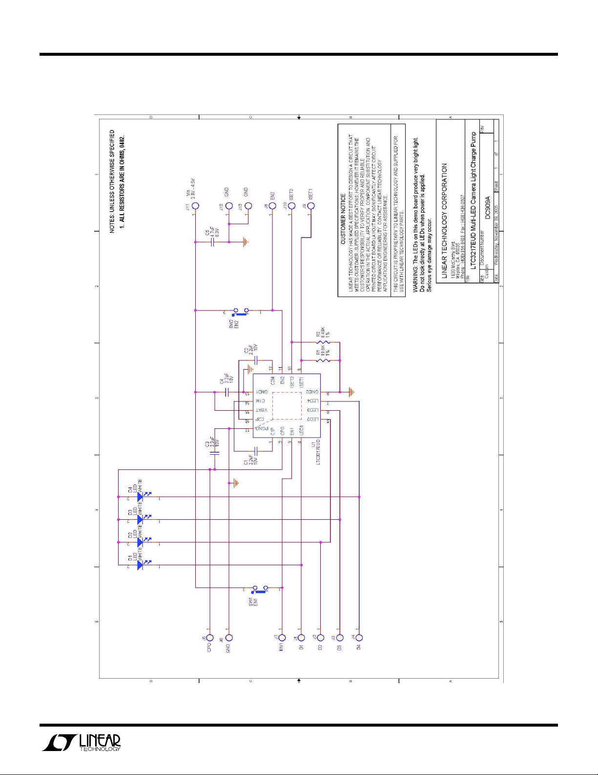
Demonstration Circuit 909 is a Multi-LED Camera
Light Charge Pump featuring the LTC3217.
The LTC3217 is a low noise charge pump designed to
power four high current LEDs. The LTC3217 requires
only four small ceramic capacitors plus two resistors
to form a complete LED power supply and a current
controller.
Built-in soft-start circuitry prevents excessive inrush
current during start-up and mode changes. High
switching frequency enables the use of small external
capacitors. Independent high and low current settings are programmed by two external resistors.
Shutdown mode and current output levels are selected via two logic inputs. The intensity of the dis-
QUICK START PROCEDURE
The DC909 is only intended for continuous operation at a current level of 300mA or less. As a result, the higher
current settings should only be used for periods less than 10 seconds.
play may be adjusted by pressing the EN1, EN2, or
both buttons. The intensity may be further controlled
by pulse width modulating EN2.
An ultra-low dropout current source maintains accurate LED current at very low I
mode switching optimizes efficiency by monitoring
the voltage across the LED current source and
switching modes only when ILED dropout is detected.
Design files for this circuit board are available. Call
the LTC factory.
, LTC and LT are registered trademarks of Linear Technology Corporation.
voltages. Automatic
LED
The use of the Demo Circuit 909 requires a DC
power supply capable of supplying at least 1A of
current.
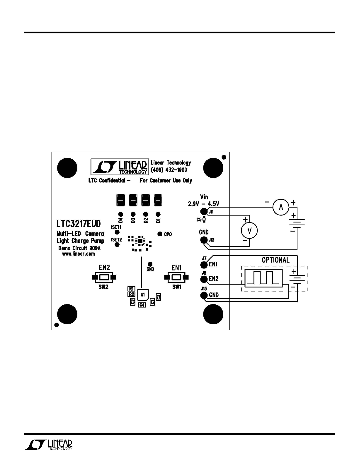
1. Connect the DC power supply across the Vin
and GND terminals of the board as shown in
Figure 1. For best stability and noise performance, use the shortest leads possible between
the board and the supply. Capacitor C5 has
been placed on the board to assist in offsetting
the effects of long power supply leads.
2. Set the output of the supply to a voltage between 2.9V and 4.5V.
3. Pressing either EN1, EN2, or both of the enable
buttons will enable the part and illuminate the
LED. The individual LED current settings for the
set enable pins are shown in the table 1.
TABLE 1. Enable Pin Truth Table
EN2 EN1 I
The ISET resistors (R1 and R2) may be replaced with different values to achieve other
current levels. The resistance required
(RSET [Ω]) to achieve a desired LED current
(I
[A]) may be approximately determined by
LED
the following equation:
RSET=488/I
Pulse width modulation may be performed on
demo circuit 909 by connecting a pulse genera-
LED
1
Page 2
QUICK START GUIDE FOR DEMONSTRATION CIRCUIT 909
MULTI-LED CAMERA LIGHT CHARGE PUMP
LTC3217
WARNING: The LEDs on this demo board produce very bright light. Do not look directly at LEDs when power is
applied. Serious eye damage may occur.
tor between the
the high pulse voltage to no greater than
VIN+0.3V and the low pulse voltage to 0V. The
pulse may be varied from a minimum pulse
width of 50us and a maximum off time of 1ms to
a 100% duty cycle. See the LTC3217 data sheet
for more information on this.
EN2
and
GND
terminals. Set
Figure 1. Proper Measurement Equipment Setup for DC909
2
Page 3
QUICK START GUIDE FOR DEMONSTRATION CIRCUIT 909
MULTI-LED CAMERA LIGHT CHARGE PUMP
LTC3217
WARNING: The LEDs on this demo board produce very bright light. Do not look directly at LEDs when power is
applied. Serious eye damage may occur.
3
Page 4

Mouser Electronics
Authorized Distributor
Click to View Pricing, Inventory, Delivery & Lifecycle Information:
Analog Devices Inc.:
DC909A
 Loading...