

Page 1
83CE654
CMOS single-chip 8-bit microcontroller
with Electromagnetic Compatibility
improvements
Preliminary specification 1996 Aug 15
INTEGRATED CIRCUITS
IC20 Data Handbook
Page 2
Philips Semiconductors Preliminary specification
83CE654
CMOS single-chip 8-bit microcontroller with
Electromagnetic Compatibility improvements
2
1996 Aug 15
DESCRIPTION
The 83CE654 Single-Chip 8-Bit
Microcontroller is manufactured in an
advanced CMOS process and is a derivative
of the 80C51 microcontroller family. The
83CE654 has the same instruction set as the
80C51. The 83CE654 has 16k bytes mask
programmable ROM and 256 bytes RAM.
This device provides architectural
enhancements that make it applicable in a
variety of applications for general control
systems. The 83CE654 contains a
non-volatile 16k × 8 read-only program
memory, a volatile 256 × 8 read/write data
memory, four 8-bit I/O ports, two 16-bit
timer/event counters (identical to the timers of
the 80C51), a multi-source, two-priority-level,
nested interrupt structure, an I
2
C interface,
UART and on-chip oscillator and timing
circuits. For systems that require extra
capability, the 83CE654 can be expanded
using standard TTL compatible memories
and logic.
The device also functions as an arithmetic
processor having facilities for both binary and
BCD arithmetic plus bit-handling capabilities.
The instruction set consists of over 100
instructions: 49 one-byte, 45 two-byte and
17 three-byte. With a 16MHz crystal, 58% of
the instructions are executed in 0.75µs and
40% in 1.5µs. Multiply and divide instructions
require 3µs.
FEATURES
•80C51 central processing unit
•16k × 8 ROM expandable externally to
64k bytes
•256 × 8 RAM, expandable externally to
64k bytes
•Two standard 16-bit timer/counters
•Four 8-bit I/O ports
•I
2
C-bus serial I/O port with byte oriented
master and slave functions
•Full-duplex UART facilities
•ROM code protection
•XTAL frequency range: 1.2MHz to 16MHz
•Software enable/disable of ALE output
pulse
•Electromagnetic compatibility (EMC)
improvements
•Operating ambient temperature range:
– P83CE654 FBB T
amb
0°C to +70°C
– P83CE654 FFB T
amb
–40°C to +85°C
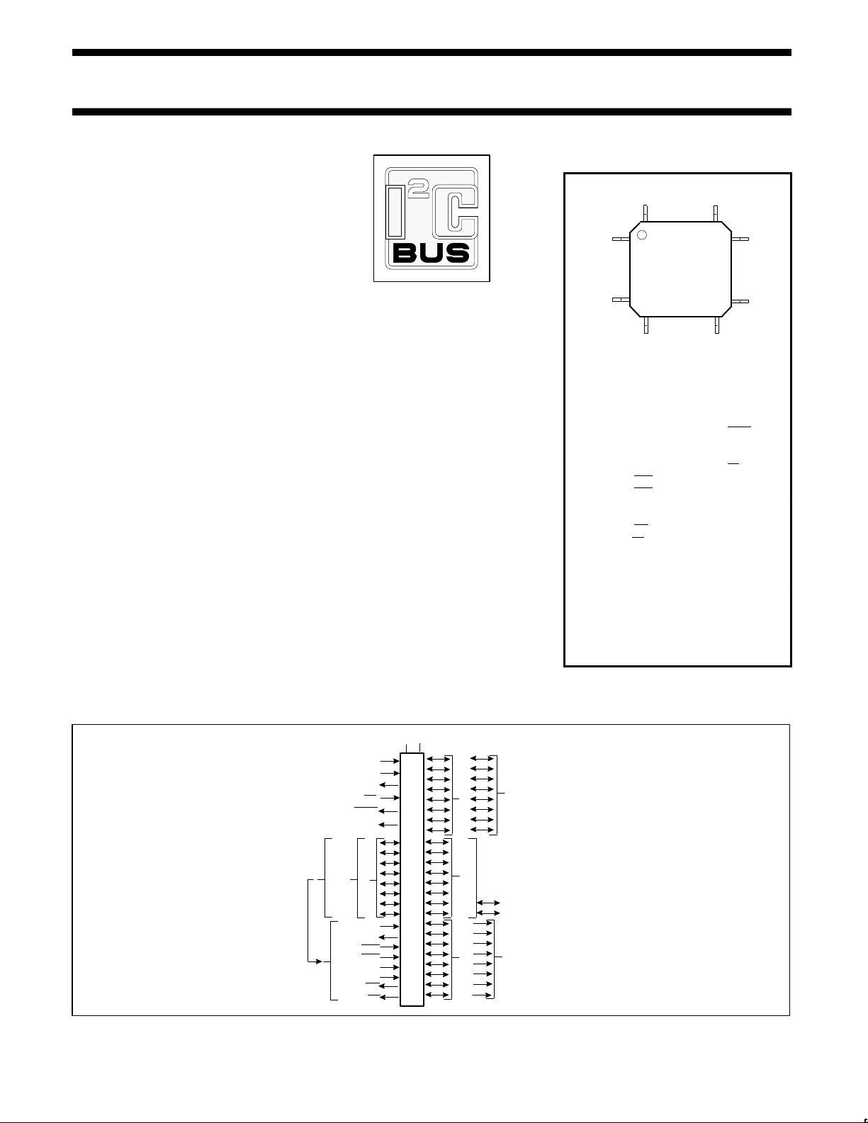
PIN CONFIGURATION
PLASTIC
QUAD
FLAT
PACK
44 34
1
11
33
23
12 22
Pin Function Pin Function
1 P1.5 23 P2.5/A13
2 P1.6/SCL 24 P2.6/A14
3 P1.7/SDA 25 P2.7/A15
4 RST 26 PSEN
5 P3.0/RxD 27 ALE
6 V
SS4
28 V
SS2
7 P3.1/TxD 29 EA
8 P3.2/INT0 30 P0.7/AD7
9 P3.3/INT1 31 P0.6/AD6
10 P3.4/T0 32 P0.5/AD5
11 P3.5/T1 33 P0.4/AD4
12 P3.6/WR 34 P0.3/AD3
13 P3.7RD 35 P0.2/AD2
14 XTAL2 36 P0.1/AD1
15 XTAL1 37 P0.0/AD0
16 V
SS1
38 V
DD2
17 V
DD1
39 V
SS3
18 P2.0/A8 40 P1.0
19 P2.1/A9 41 P1.1
20 P2.2/A10 42 P1.2
21 P2.3/A11 43 P1.3
22 P2.4/A12 44 P1.4
LOGIC SYMBOL
PORT 0PORT 1PORT 2
PORT 3
ADDRESS AND
DATA BUS
ADDRESS BUS
VSSV
DD
ALTERNATE
FUNCTIONS
RST
XTAL1
XTAL2
EA
ALE
PSEN
RxD
TxD
INT0
INT1
T0
T1
WR
RD
SCL
SDA
Page 3
Philips Semiconductors Preliminary specification
83CE654
CMOS single-chip 8-bit microcontroller with
Electromagnetic Compatibility improvements
1996 Aug 15
3
ORDERING INFORMATION
ROM
TEMPERATURE RANGE oC
AND PACKAGE
FREQUENCY
MHz
DRAWING NUMBER
P83CE654FBB 0 to +70, Plastic Quad Flat Pack 1.2 to 16 SOT307-2
1
P83CE654FFB –40 to +85, Plastic Quad Flat Pack 1.2 to 16 SOT307-2
1
NOTE:
1. SOT311 replaced by SOT307-2.
ELECTROMAGNETIC
COMPATIBILITY (EMC)
IMPROVEMENTS
Primary attention is paid on the reduction of
electromagnetic emission of the
microcontroller P83CE654.
The following features effect in reducing the
electromagnetic emission and additionally
improve the electromagnetic susceptibility:
•Two supply voltage pins (V
DD1
, V
DD2
) and
four ground pins (V
SS1
to V
SS4
)
•Separate V
DD
pins for the internal logic and
the port buffers
•Internal decoupling capacitance improves
the EMC radiation behavior and the EMC
immunity
•External capacitors are to be located as
close as possible between pins V
DD2
and
V
SS3
as well as V
DD1
and V
SS1
; ceramic
chip capacitors are recommended (100nF).
•The ALE output signal (pulses at a
frequency of f
OSC
/6) can be disabled under
software control (bit 5 in the SFR PCON:
“RFI”); if disabled, no ALE pulse will occur.
ALE pin will be pulled down internally,
switching an external address latch to a
quiet state. The MOVX instruction will still
toggle ALE as a normal MOVX. ALE will
retain its normal high value during Idle
mode and a low value during Power-down
mode while in the “RFI” reduction mode.
Additionally during internal access (EA
= 1)
ALE will toggle normally when the address
exceeds the internal program memory size.
During external access (EA
= 0) ALE will
always toggle normally, whether the flag
“RFI” is set or not.
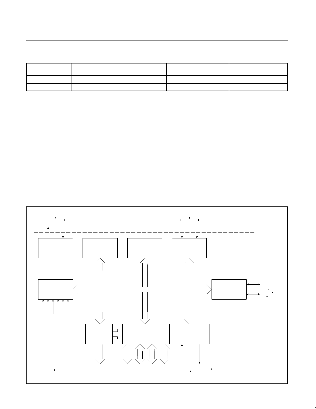
BLOCK DIAGRAM
64K BYTE BUS
EXPANSION
CONTRTOL
PROG SERIAL PORT
FULL DUPLEX UART
SYNCHRONOUS SHIFT
PROGRAMMABLE I/O
CPU
OSCILLATOR
AND
TIMING
PROGRAM
MEMORY
DATA
MEMORY
(256 x 8 RAM)
TWO 16-BIT
TIMER/EVENT
COUNTERS
I
2
C SERIAL I/O
SDA
SCL
SHARED
WITH
PORT 1
T0 T1
COUNTER INPUTS SHARED WITH PORT 3
XTAL2 XTAL1
FREQUENCY
REFERENCE
INTERNAL
INTERRUPTS
INT0
INT1
EXTERNAL INTERRUPTS
SHARED WITH PORT 3
CONTROL
PARALLEL PORTS,
ADDRESS/DATA BUS
AND I/O PINS
SERIAL IN SERIAL OUT
SHARED WITH
PORT 3
(16K x 8 ROM)
Page 4
Philips Semiconductors Preliminary specification
83CE654
CMOS single-chip 8-bit microcontroller with
Electromagnetic Compatibility improvements
1996 Aug 15
4
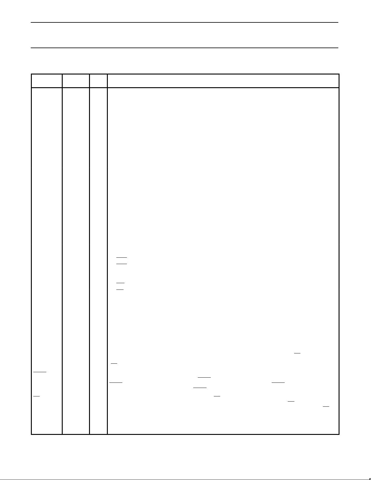
PIN DESCRIPTIONS
MNEMONIC
PIN
NUMBER
TYPE NAME AND FUNCTION
V
SS1
, V
SS2
,
V
SS3
, V
SS4
16, 28,
39, 6
I Ground: 0V reference. All pins must be connected.
V
DD1
, V
DD2
17, 38 I Power Supply: This is the power supply voltage for normal, idle, and power-down operation. Both pins
must be connected.
P0.0–0.7 37–30 I/O Port 0: Port 0 is an open-drain, bidirectional I/O port. Port 0 pins that have 1s written to them float and can
be used as high-impedance inputs. Port 0 is also the multiplexed low-order address and data bus during
accesses to external program and data memory. In this application, it uses strong internal pull-ups when
emitting 1s. Port 0 can sink/source 8 LSTTL inputs.
P1.0–P1.7 40–44,
1–3
I/O Port 1: Port 1 is an 8-bit bidirectional I/O port with internal pull-ups, except P1.6 and P1.7 which are open
drain. Port 1 pins that have 1s written to them are pulled high by the internal pull-ups and can be used as
inputs. As inputs, port 1 pins that are externally pulled low will source current because of the internal
pull-ups. (See DC Electrical Characteristics: I
IL
). Port 1 also receives the low-order address byte during
program memory verification. Alternate functions include:
P1.6 2 I/O SCL: I2C-bus serial port clock line.
P1.7 3 I/O SDA: I2C-bus serial port data line.
P2.0–P2.7 18–25 I/O Port 2: Port 2 is an 8-bit bidirectional I/O port with internal pull-ups. Port 2 pins that have 1s written to
them are pulled high by the internal pull-ups and can be used as inputs. As inputs, port 2 pins that are
externally being pulled low will source current because of the internal pull-ups. (See DC Electrical
Characteristics: I
IL
). Port 2 emits the high-order address byte during fetches from external program
memory and during accesses to external data memory that use 16-bit addresses (MOVX @DPTR). In this
application, it uses strong internal pull-ups when emitting 1s. During accesses to external data memory
that use 8-bit addresses (MOV @Ri), port 2 emits the contents of the P2 special function register.
P3.0–P3.7 5,
7–13
I/O Port 3: Port 3 is an 8-bit bidirectional I/O port with internal pull-ups. Port 3 pins that have 1s written to
them are pulled high by the internal pull-ups and can be used as inputs. As inputs, port 3 pins that are
externally being pulled low will source current because of the pull-ups. (See DC Electrical Characteristics:
I
IL
). Port 3 also serves the special features of the 80C51 family, as listed below:
5 I RxD (P3.0): Serial input port
7 O TxD (P3.1): Serial output port
8 I INT0 (P3.2): External interrupt 0 or gate control input for timer/event counter 0
9 I INT1 (P3.3): External interrupt 1 or gate control input for timer/event counter 1
10 I T0 (P3.4): Timer 0 external input
11 I T1 (P3.5): Timer 1 external input
12 O WR (P3.6): External data memory write strobe
13 O RD (P3.7): External data memory read strobe
RST 4 I Reset: A high on this pin for two machine cycles while the oscillator is running, resets the device. An
internal pull-down resistor to V
SS
permits a power-on reset using only an external capacitor to VDD.
ALE 27 I/O Address Latch Enable: Output pulse for latching the low byte of the address during an access to external
memory. In normal operation, ALE is emitted at a constant rate of 1/6 the oscillator frequency, and can be
used for external timing or clocking. Note that one ALE pulse is skipped during each access to external
data memory. ALE can sink/source 8 LSTTL inputs. It can drive CMOS inputs without an external pull-up.
To prohibit the toggling of ALE pin (RFI noise reduction) the bit RFI in the PCON Register (PCON.5) must
be set by software. This bit is cleared on RESET and can be cleared by software. When set, ALE pin will
be pulled down internally, switching an external address latch to a quiet state. The MOVX instruction will
still toggle ALE as a normal MOVX. ALE will retain its normal high value during Idle mode and a low value
during Power-down mode while in the “RFI” mode. Additionally during internal access (EA
= 1) ALE will
toggle normally when the address exceeds the internal program memory size. During external access
(EA
= 0) ALE will always toggle normally, whether the flag “RFI” is set or not.
PSEN 26 O Program Store Enable: The read strobe to external program memory. When the 83CE654 is executing
code from the external program memory, PSEN
is activated twice each machine cycle, except that two
PSEN
activations are skipped during each access to external data memory. PSEN is not activated during
fetches from internal program memory. PSEN
can sink/source 8 LSTTL inputs.
EA 29 I External Access Enable: when, during RESET, EA is held at a TTL HIGH level the CPU executes out of
the internal program ROM, provided the program counter is less than 16384. When EA
is held at a TTL
LOW level during RESET, the CPU executes out of external program memory via Port 0 and Port 2. EA
is
not allowed to float.
XTAL1 15 I Crystal 1: Input to the inverting oscillator amplifier and input to the internal clock generator circuits.
XTAL2 14 O Crystal 2: Output from the inverting oscillator amplifier.
NOTE:
To avoid “latch-up” effect at power-on, the voltage on any pin at any time must not be higher or lower than V
DD
+ 0.5V or VSS – 0.5V,
respectively.
Page 5
Philips Semiconductors Preliminary specification
83CE654
CMOS single-chip 8-bit microcontroller with
Electromagnetic Compatibility improvements
1996 Aug 15
5
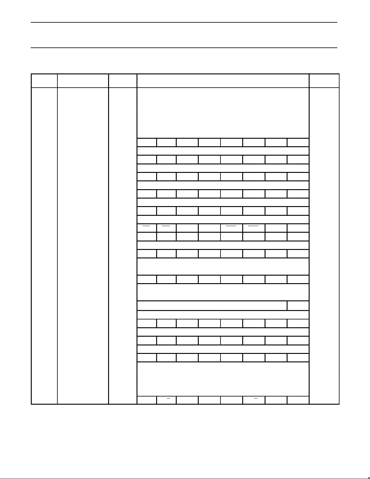
Table 1. 83CE654 Special Function Registers
SYMBOL DESCRIPTION
DIRECT
ADDRESS
BIT ADDRESS, SYMBOL, OR ALTERNATIVE PORT FUNCTION
MSB LSB
RESET
VALUE
ACC* Accumulator E0H E7 E6 E5 E4 E3 E2 E1 E0 00H
B* B register F0H F7 F6 F5 F4 F3 F2 F1 F0 00H
DPTR:
DPH
DPL
Data pointer
(2 bytes)
Data pointer high
Data pointer low
83H
82H
00H
00H
AF AE AD AC AB AA A9 A8
IE*# Interrupt enable A8H EA ES1 ES0 ET1 EX1 ET0 EX0 0x000000B
BF BE BD BC BB BA B9 B8
IP*# Interrupt priority B8H – PS1 PS0 PT1 PX1 PT0 PX0 xx000000B
87 86 85 84 83 82 81 80
P0* Port 0 80H AD7 AD6 AD5 AD4 AD3 AD2 AD1 AD0 FFH
97 96 95 94 93 92 91 90
P1*# Port 1 90H SDA SCL FFH
A7 A6 A5 A4 A3 A2 A1 A0
P2* Port 2 A0H A15 A14 A13 A12 A11 A10 A9 A8 FFH
B7 B6 B5 B4 B3 B2 B1 B0
P3* Port 3 B0H RD WR T1 T0 INT1 INT0 TXD RXD FFH
PCON# Power control 87H SMOD – RFI – GF1 GF0 PD IDL 0xxx0000B
9F 9E 9D 9C 9B 9A 99 98
S0CON*# Serial 0 port control 98H SM0 SM1 SM2 REN TB8 RB8 TI RI 00H
S0BUF# Serial 0 data buffer 99H xxxxxxxxB
D7 D6 D5 D4 D3 D2 D1 D0
PSW* Program status word D0H CY AC F0 RS1 RS0 OV F1 P 00H
S1DAT# Serial 1 data DAH 00H
SP Stack pointer 81H 07H
S1ADR# Serial 1 address DBH
SLAVE ADDRESS
GC 00H
S1STA# Serial 1 status D9H SC4 SC3 SC2 SC1 SC0 0 0 0 F8H
DF DE DD DC DB DA D9 D8
S1CON*# Serial 1 control D8H CR2 ENS1 STA STO SI AA CR1 CR0 00000000B
8F 8E 8D 8C 8B 8A 89 88
TCON* Timer control 88H TF1 TR1 TF0 TR0 IE1 IT1 IE0 IT0 00H
TH1 Timer high 1 8DH 00H
TH0 Timer high 0 8CH 00H
TL1 Timer low 1 8BH 00H
TL0 Timer low 0 8AH 00H
TMOD Timer mode 89H GATE C/T M1 M0 GATE C/T M1 M0 00H
* SFRs are bit addressable.
# SFRs are modified from or added to the 80C51 SFRs.
Page 6
Philips Semiconductors Preliminary specification
83CE654
CMOS single-chip 8-bit microcontroller with
Electromagnetic Compatibility improvements
1996 Aug 15
6
ROM CODE PROTECTION
The 83CE654 has an additional security
feature. ROM code protection may be
selected by setting a mask-programmable
security bit (i.e., user dependent). This
feature may be requested during ROM code
submission. When selected, the ROM code is
protected and cannot be read out at any time
by any test mode or by any instruction in the
external program memory space.
The MOVC instructions are the only
instructions that have access to program
code in the internal or external program
memory. The EA
input is latched during
RESET and is “don’t care” after RESET (also
if the security bit is not set). This
implementation prevents reading internal
program code by switching from external
program memory to internal program memory
during a MOVC instruction or any other
instruction that uses immediate data.
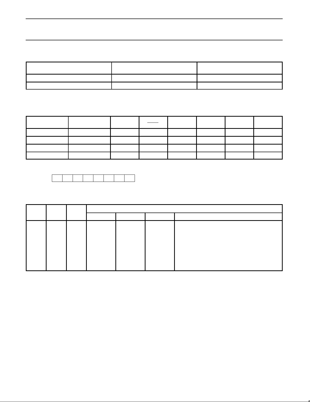
Table 2 lists the access to the internal and
external program memory by the MOVC
instructions when the security bit has been
set to a logical “1”:
OSCILLATOR
CHARACTERISTICS
XTAL1 and XTAL2 are the input and output,
respectively, of an inverting amplifier. The
pins can be configured for use as an on-chip
oscillator, as shown in the Logic Symbol,
page 2.
To drive the device from an external clock
source, XTAL1 should be driven while XTAL2
is left unconnected. There are no
requirements on the duty cycle of the
external clock signal, because the input to
the internal clock circuitry is through a
divide-by-two flip-flop. However, minimum
and maximum high and low times specified in
the data sheet must be observed.
Reset
A reset is accomplished by holding the RST
pin high for at least two machine cycles
(24 oscillator periods), while the oscillator is
running. To insure a good power-on reset, the
RST pin must be high long enough to allow
the oscillator time to start up (normally a few
milliseconds) plus two machine cycles. At
power-on, the voltage on V
DD
and RST must
come up at the same time for a proper
start-up.
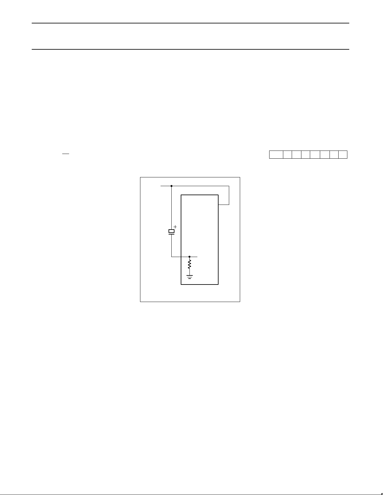
Power-on Reset (See Figure 1.)
When V
DD
is turned on, and provided its
rise-time does not exceed 10ms, an
automatic reset can be obtained by
connecting the RST pin to V
DD
via a 2.2µF
capacitor. When the power is switched on,
the voltage on the RST pin is equal to V
DD
minus the capacitor voltage, and decreases
from V
DD
as the capacitor charges through
the internal resistor (R
RST
) to ground. The
larger the capacitor, the more slowly V
RST
decreases. V
RST
must remain above the
lower threshold of the Schmitt trigger long
enough to effect a complete reset. The time
required is the oscillator start-up time, plus 2
machine cycles.
83CE654
V
DD
RST
R
RST
2.2µF
V
DD
Figure 1. Power-on Reset
Idle Mode
In the idle mode, the CPU puts itself to sleep
while all of the on-chip peripherals stay
active. The instruction to invoke the idle
mode is the last instruction executed in the
normal operating mode before the idle mode
is activated. The CPU contents, the on-chip
RAM, and all of the special function registers
remain intact during this mode. The idle
mode can be terminated either by any
enabled interrupt (at which time the process
is picked up at the interrupt service routine
and continued), or by a hardware reset which
starts the processor in the same manner as a
power-on reset.
Power-Down Mode
In the power-down mode, the oscillator is
stopped and the instruction to invoke
power-down is the last instruction executed.
Only the contents of the on-chip RAM are
preserved. A hardware reset is the only way
to terminate the power-down mode. the
control bits for the reduced power modes are
in the special function register PCON. Table 3
shows the state of the I/O ports during low
current operating modes.
Power Control Register PCON
These special modes are activated by
software via the Special Function Register
PCON. Its hardware address is 87H. PCON
is not bit addressable. The reset value of
PCON is (0x0x0000).
PCON
(87H)
SMOD – RFI – GF1 GF0 PD IDL
7 6 5 4 3 2 1 0
Bit Symbol Function
PCON.7 SMOD Double Baud rate bit.
When set to logic 1 the
baud rate is doubled when
Timer 1 is used to
generate baud rate, and
the Serial Port is used in
modes 1, 2 or 3.
PCON.6 – (reserved for future use*)
PCON.5 RFI When set to logic 1 the
toggling of ALE pin is
prohibited. This bit is
cleared on RESET.
PCON.4 – (reserved for future use*)
PCON.3 GF1 General purpose flag bit.
PCON.2 GF0 General purpose flag bit.
PCON.1 PD Power-down bit. Setting
this bit activates
Power-down mode.
PCON.0 IDL Idle mode bit. Setting this
bit activates the Idle
mode. If 1s are written to
PD and IDL at the same
time, PD takes
precedence.
NOTE:
* User software should not write 1s to
reserved bits. These bits may be used in
future 80C51 family products to invoke
new features. In that case, the reset or
inactive value of the new bit will be 0, and
its active value will be 1. The value read
from a reserved bit is indeterminate.
I2C Serial Communication—SIO1
The I2C serial port is identical to the I2C
serial port on the 8XC552. The operation of
this subsystem is described in detail in the
8XC552 section of this manual.
Note that in both the 83CE654 and the
8XC552 the I
2
C pins are alternate functions
to port pins P1.6 and P1.7. Because of this,
P1.6 and P1.7 on these parts do not have a
pull-up structure as found on the 80C51.
Therefore P1.6 and P1.7 have open drain
outputs on the 83CE654.
Page 7
Philips Semiconductors Preliminary specification
83CE654
CMOS single-chip 8-bit microcontroller with
Electromagnetic Compatibility improvements
1996 Aug 15
7
Table 2.
ACCESS TO INTERNAL
PROGRAM MEMORY
ACCESS TO EXTERNAL
PROGRAM MEMORY
MOVC in internal program memory YES YES
MOVC in external program memory NO YES
NOTE:
If the security bit has been set to a logical 0, there are no restrictions for the MOVC instructions.
Table 3. External Pin Status During Idle and Power-Down Mode
MODE
PROGRAM
MEMORY
ALE PSEN PORT 0 PORT 1 PORT 2 PORT 3
Idle Internal 1 1 Data Data Data Data
Idle External 1 1 Float Data Address Data
Power-down Internal 0 0 Data Data Data Data
Power-down External 0 0 Float Data Data Data
Serial Control Register (S1CON) – See Table 4
CR2 ENS1 STA STO SI AA CR1 CR0
S1CON (D8H)
Bits CR0, CR1 and CR2 determine the serial clock frequency that is generated in the master mode of operation.
Table 4. Serial Clock Rates
BIT FREQUENCY (kHz) AT f
OSC
CR2 CR1 CR0 6MHz 12MHz 16MHz f
OSC
DIVIDED BY
0 0 0 23 47 63 256
0 0 1 27 54 71 224
0 1 0 31 63 83 192
0 1 1 37 75 100 160
1 0 0 6.25 12.5 17 960
1 0 1 50 100 133
1
120
1 1 0 100 200
1
267
1
60
1 1 1 0.24 < 62.5 0.49 < 62.5 0.65 < 55.6 96 × (256 – (reload value Timer 1))
0 < 255 0 < 254 0 < 253 reload value range Timer 1 (in mode 2)
NOTES:
1. These frequencies exceed the upper limit of 100kHz of the I
2
C-bus specification and cannot be used in an I2C-bus application.
Page 8
Philips Semiconductors Preliminary specification
83CE654
CMOS single-chip 8-bit microcontroller with
Electromagnetic Compatibility improvements
1996 Aug 15
8
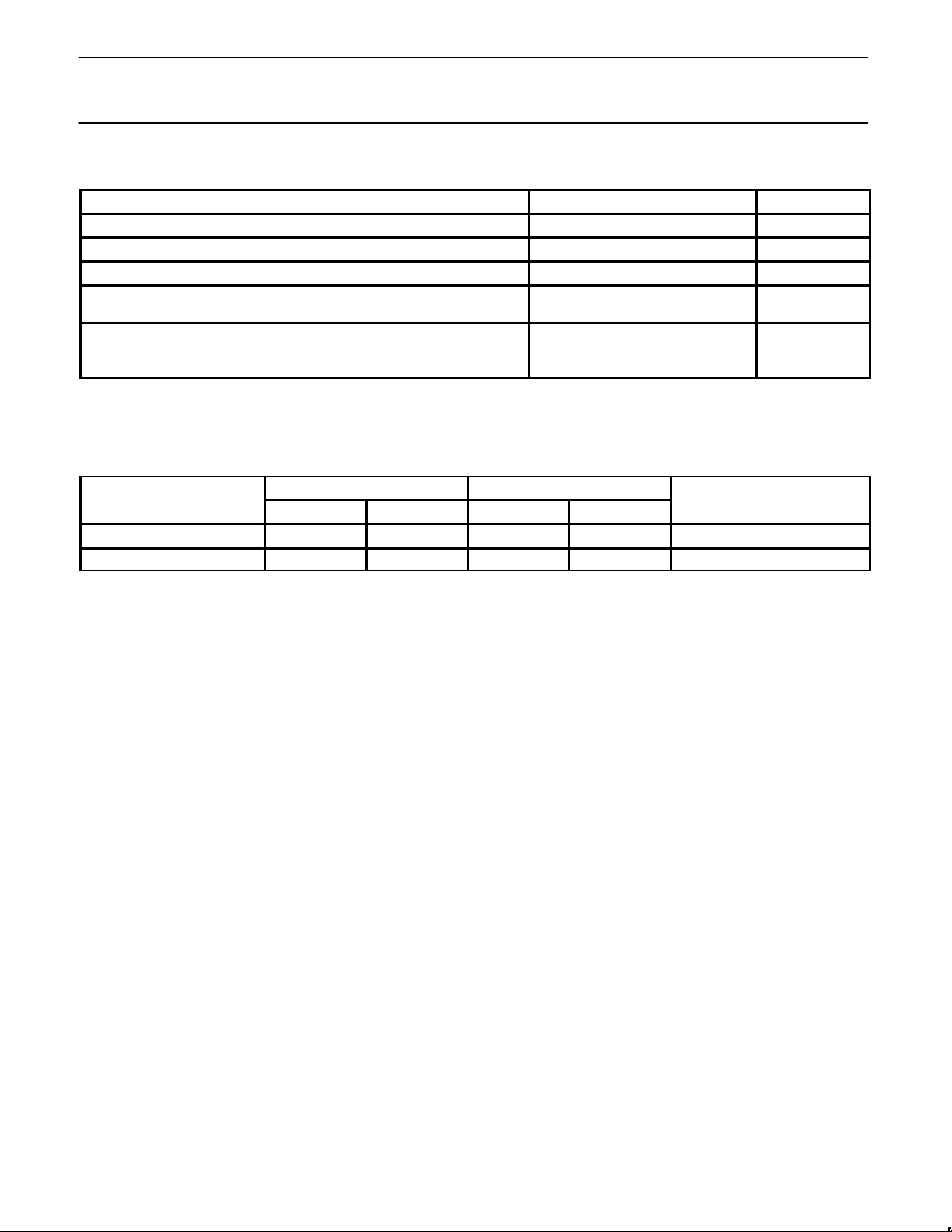
ABSOLUTE MAXIMUM RATINGS
PARAMETER RATING UNIT
Voltage on VDD to V
SS
–0.5 to +6.5 V
Voltage on any pin to V
SS
–0.5 to VDD+0.5 V
Storage temperature range –65 to +150 °C
Power dissipation (based on package heat transfer limitations, not device
power consumption)
1
1 W
Operating ambient temperature range
FBB 0 to +70 °C
FFB –40 to +85 °C
NOTE:
1. Stresses above those listed under Absolute Maximum Ratings may cause permanent damage to the device. this is a stress rating only and
functional operation of the device at these or any conditions other than those described in the AC and DC Electrical Characteristics section
of this specification is not implied. Exposure to Absolute Maximum Rating conditions for extended periods may affect device reliability.
DEVICE SPECIFICATIONS
SUPPLY VOLTAGE (V) FREQUENCY (MHz)
TEMPERATURE RANGE
TYPE
MIN. MAX. MIN. MAX.
TEMPERATURE RANGE
(°C)
P83CE654FBB 4.5 5.5 1.2 16 0 to +70
P83CE654FFB 4.5 5.5 1.2 16 –40 to +85
Page 9
Philips Semiconductors Preliminary specification
83CE654
CMOS single-chip 8-bit microcontroller with
Electromagnetic Compatibility improvements
1996 Aug 15
9
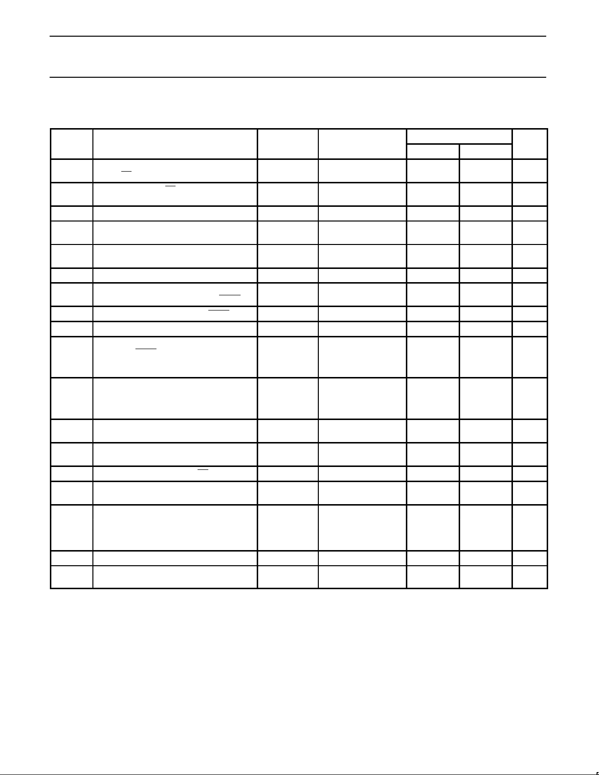
DC ELECTRICAL CHARACTERISTICS
VDD = 5V (±10%), VSS = 0V, T
amb
= 0°C to +70°C or –40°C to +85°C
TEST LIMITS
SYMBOL PARAMETER PART TYPE CONDITIONS MIN. MAX. UNIT
V
IL
Input low voltage,
except EA
, P1.6/SCL, P1.7/SDA
0 to +70°C
–40 to +85°C
–0.5
–0.5
0.2VDD–0.1
0.2V
DD
–0.15
V
V
V
IL1
Input low voltage to EA 0 to +70°C
–40 to +85°C
–0.5
–0.5
0.2VDD–0.3
0.2V
DD
–0.35
V
V
V
IL2
Input low voltage to P1.6/SCL, P1.7/SDA
6
–0.5 0.3V
DD
V
V
IH
Input high voltage, except XTAL1, RST,
P1.6/SCL, P1.7/SDA
0 to +70°C
–40 to +85°C
0.2VDD+0.9
0.2V
DD
+1.0
VDD+0.5
V
DD
+0.5
V
V
V
IH1
Input high voltage, XTAL1, RST 0 to +70°C
–40 to +85°C
0.7V
DD
0.7VDD+0.1
VDD+0.5
V
DD
+0.5
V
V
V
IH2
Input high voltage, P1.6/SCL, P1.7/SDA
6
0.7V
DD
6.0 V
V
OL
Output low voltage, ports 1, 2, 3,
except P1.6/SCL, P1.7/SDA
4,
ALE, PSEN
IOL = 1.6mA
7
0.45 V
V
OL1
Output low voltage, port 0, ALE, PSEN
4
IOL = 3.2mA
7
0.45 V
V
OL2
Output low voltage, P1.6/SCL, P1.7/SDA
4
IOL = 3.0mA
7
0.4 V
V
OH
Output high voltage, ports 1, 2, 3, except P1.6,
P1.7, ALE, PSEN
IOH = –60µA;
V
DD
= 5V (± 10%)
I
OH
= –25µA
I
OH
= –10µA
2.4
0.75V
DD
0.9V
DD
V
V
V
V
OH1
Output high voltage;
port 0 in external bus mode
5
IOH = –800µA;
V
DD
= 5V (± 10%)
I
OH
= –300µA
I
OH
= –80µA
2.4
0.75V
DD
0.9V
DD
V
V
V
I
IL
Logical 0 input current, ports 1, 2, 3,
except P1.6/SCL, P1.7/SDA
0 to +70°C
–40 to +85°C
Vi = 0.45V
V
i
= 0.45V
–50
–75
µA
µA
I
TL
Logical 1-to-0 transition current, ports 1, 2, 3,
except P1.6/SCL, P1.7/SDA
0 to +70°C
–40 to +85°C
Vi = 2.0V
V
i
= 2.0V
–650
–750
µA
µA
I
LI1
Input leakage current, port 0, EA 0.45V < V
i
< V
DD
±10 µA
I
LI2
Input leakage current, P1.6/SCL, P1.7/SDA 0V < V
i
< 5.5V
0V < V
DD
< 5.5V
±10 µA
I
DD
Power supply current:
Active mode @ 16MHz
1, 8
VDD = 5.5V 22 mA
Idle mode @ 16MHz
2, 8
VDD = 5V ± 10% 6 mA
Power down mode
3
@2V < VPD < V
DDMAX
50 µA
R
RST
Internal reset pull-down resistor 50 150 kΩ
C
IO
Pin capacitance of I/O buffer Freq.=1MHz;
T
amb
= 25°C
10 pF
NOTES: See Next Page.
Page 10
Philips Semiconductors Preliminary specification
83CE654
CMOS single-chip 8-bit microcontroller with
Electromagnetic Compatibility improvements
1996 Aug 15
10
NOTES FOR DC ELECTRICAL CHARACTERISTICS:
1. The operating supply current is measured with all output pins disconnected; XTAL1 driven with t
r
= tf = 5ns; VIL = VSS + 0.5V;
V
IH
= V
DD
–0.5V; XTAL2 not connected; EA = RST = Port 0 = P1.6 = P1.7 = VDD.
2. The idle mode supply current is measured with all output pins disconnected; XTAL1 driven with t
r
= tf = 5ns; VIL = VSS + 0.5V;
V
IH
= V
DD
–0.5V; XTAL2 not connected; Port 0 = P1.6 = P1.7 = VDD; EA = RST = VSS.
3. The power-down current is measured with all output pins disconnected; XTAL2 not connected; Port 0 = P1.6 = P1.7 = V
DD
;
EA
= XTAL1 = RST = VSS.
4. Capacitive loading on ports 0 and 2 may cause spurious noise to be superimposed on the V
OL
s of ALE and ports 1 and 3. The noise is due
to external bus capacitance discharging into the port 0 and port 2 pins when these pins make 1-to-0 transitions during bus operations. In the
worst cases (capacitive loading > 100pF), the noise pulse on the ALE pin may exceed 0.8V . In such cases, it may be desirable to qualify
ALE with a Schmitt Trigger, or use an address latch with a Schmitt Trigger STROBE input.
5. Capacitive loading on ports 0 and 2 may cause the V
OH
on ALE and PSEN to momentarily fall below the 0.9VDD specification when the
address bits are stabilizing.
6. The input threshold voltage of P1.6 and P1.7 (SIO1) meets the I
2
C specification, so an input voltage below 0.3VDD will be recognized as a
logic 0 while an input voltage above 0.7V
DD
will be recognized as a logic 1.
7. Under steady state (non-transient) conditions, I
OL
must be externally limited as follows: Maximum IOL = 10mA per port pin; Maximum
I
OL
= 26mA total for Port 0; Maximum IOL = 15mA total for Ports 1, 2, and 3; Maximum IOL = 71mA total for all output pins. If IOL exceeds the
test conditions, V
OL
may exceed the related specification. Pins are not guaranteed to sink current greater than the listed test conditions.
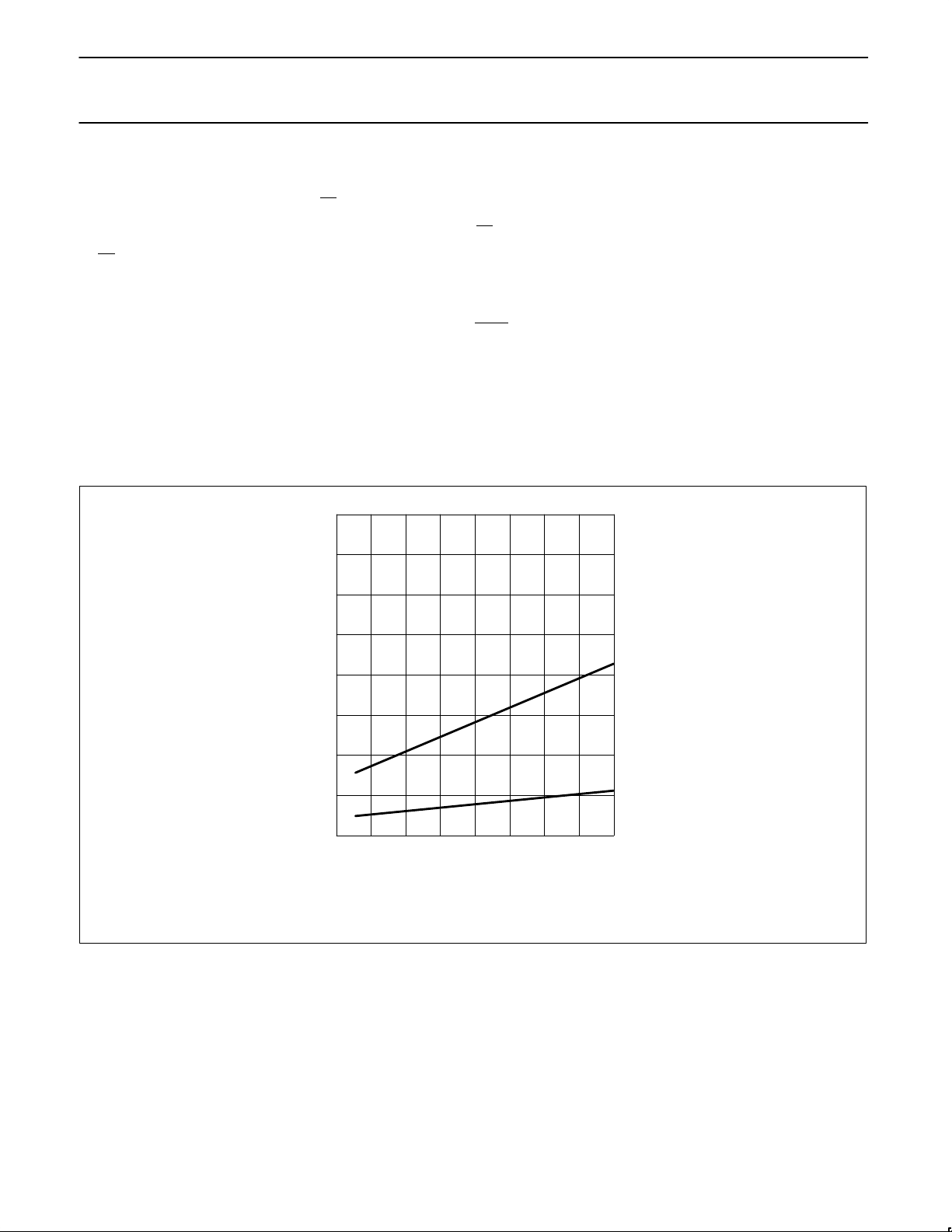
8. I
DDMAX
for the 80/83CE654 at the other frequencies can be derived from Figure 2, where FREQ is the external oscillator frequency in MHz.
I
DDMAX
is given in mA.
40
30
20
10
0
0 4 8 12 16
MAXIMUM OPERATING MODE:
V
DD
= MAX
MAXIMUM IDLE MODE:
V
DD
= MAX
f
XTAL1
(MHz)
I
DD
(mA)
VALID ONLY WITHIN FREQUENCY SPECIFICATIONS OF DEVICE UNDER TEST.
Figure 2. IDD vs. Frequency
Page 11
Philips Semiconductors Preliminary specification
83CE654
CMOS single-chip 8-bit microcontroller with
Electromagnetic Compatibility improvements
1996 Aug 15
11
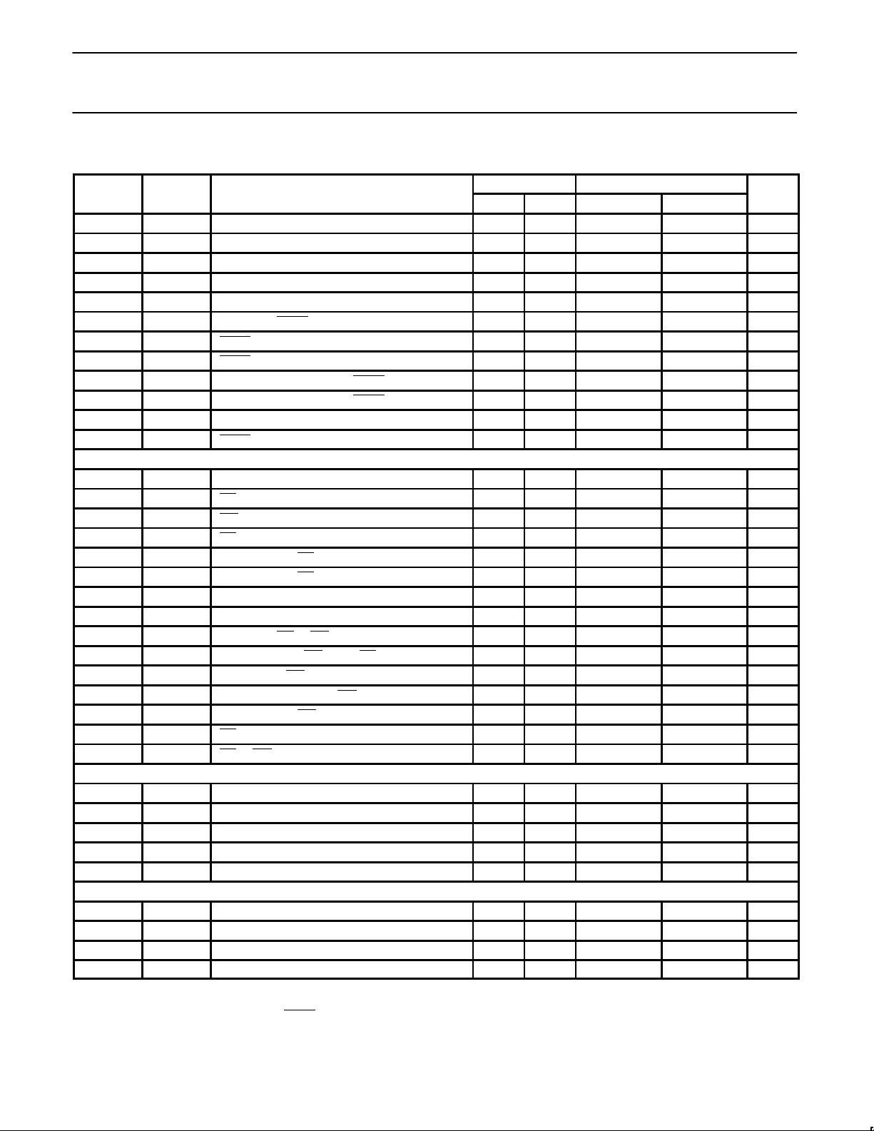
AC ELECTRICAL CHARACTERISTICS
1, 2
16MHz CLOCK VARIABLE CLOCK
SYMBOL FIGURE PARAMETER MIN MAX MIN MAX UNIT
1/t
CLCL
3 Oscillator frequency 1.2 16 MHz
t
LHLL
3 ALE pulse width 85 2t
CLCL
–40 ns
t
AVLL
3 Address valid to ALE low 8 t
CLCL
–55 ns
t
LLAX
3 Address hold after ALE low 28 t
CLCL
–35 ns
t
LLIV
3 ALE low to valid instruction in 150 4t
CLCL
–100 ns
t
LLPL
3 ALE low to PSEN low 23 t
CLCL
–40 ns
t
PLPH
3 PSEN pulse width 143 3t
CLCL
–45 ns
t
PLIV
3 PSEN low to valid instruction in 83 3t
CLCL
–105 ns
t
PXIX
3 Input instruction hold after PSEN 0 0 ns
t
PXIZ
3 Input instruction float after PSEN 38 t
CLCL
–25 ns
t
AVIV
3 Address to valid instruction in 208 5t
CLCL
–105 ns
t
PLAZ
3 PSEN low to address float 10 10 ns
Data Memory
t
AVLL
4, 5 Address valid to ALE low 8 t
CLCL
–55 ns
t
RLRH
4, 5 RD pulse width 275 6t
CLCL
–100 ns
t
WLWH
4, 5 WR pulse width 275 6t
CLCL
–100 ns
t
RLDV
4, 5 RD low to valid data in 148 5t
CLCL
–165 ns
t
RHDX
4, 5 Data hold after RD 0 0 ns
t
RHDZ
4, 5 Data float after RD 55 2t
CLCL
–70 ns
t
LLDV
4, 5 ALE low to valid data in 350 8t
CLCL
–150 ns
t
AVDV
4, 5 Address to valid data in 398 9t
CLCL
–165 ns
t
LLWL
4, 5 ALE low to RD or WR low 138 238 3t
CLCL
–50 3t
CLCL
+50 ns
t
AVWL
4, 5 Address valid to WR low or RD low 120 4t
CLCL
–130 ns
t
QVWX
4, 5 Data valid to WR transition 3 t
CLCL
–60 ns
t
DW
4, 5 Data setup time before WR 288 7t
CLCL
–150 ns
t
WHQX
4, 5 Data hold after WR 13 t
CLCL
–50 ns
t
RLAZ
4, 5 RD low to address float 0 0 ns
t
WHLH
4, 5 RD or WR high to ALE high 23 103 t
CLCL
–40 t
CLCL
+40 ns
Shift Register
3
t
XLXL
6 Serial port clock cycle time 0.75 12t
CLCL
µs
t
QVXH
6 Output data setup to clock rising edge 492 10t
CLCL
–133 ns
t
XHQX
6 Output data hold after clock rising edge 80 2t
CLCL
–117 ns
t
XHDX
6 Input data hold after clock rising edge 0 0 ns
t
XHDV
6 Clock rising edge to input data valid 492 10t
CLCL
–133 ns
External Clock
t
CHCX
7 High time 20 20 t
CLCL –
t
LOW
ns
t
CLCX
7 Low time 20 20 t
CLCL –
t
HIGH
ns
t
CLCH
7 Rise time 20 20 ns
t
CHCL
7 Fall time 20 20 ns
NOTES:
1. Parameters are valid over operating temperature range unless otherwise specified.
2. Load capacitance for port 0, ALE, and PSEN
= 100pF, load capacitance for all other outputs = 80pF.
3. Test condition: T
amb
= 0°C to +70C; VDD = 5V + 10%; VSS = 0V; load capacitance = 80pF.
Page 12
Philips Semiconductors Preliminary specification
83CE654
CMOS single-chip 8-bit microcontroller with
Electromagnetic Compatibility improvements
1996 Aug 15
12
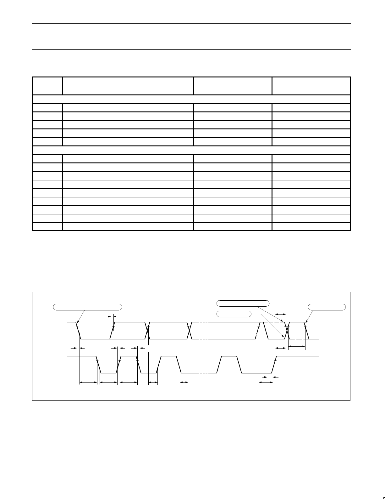
AC ELECTRICAL CHARACTERISTICS – I2C INTERFACE
SYMBOL PARAMETER INPUT OUTPUT
SCL TIMING CHARACTERISTICS
t
HD;STA
START condition hold time ≥ 14 t
CLCL
> 4.0µs
1
t
LOW
SCL LOW time ≥ 16 t
CLCL
> 4.7µs
1
t
HIGH
SCL HIGH time ≥ 14 t
CLCL
> 4.0µs
1
t
RC
SCL rise time ≤ 1µs –
2
t
FC
SCL fall time ≤ 0.3µs < 0.3µs
3
SDA TIMING CHARACTERISTICS
t
SU;DAT1
Data set-up time ≥ 250ns > 20 t
CLCL
– t
RD
t
SU;DAT2
SDA set-up time (before rep. START cond.) ≥ 250ns > 1µs
1
t
SU;DAT3
SDA set-up time (before STOP cond.) ≥ 250ns > 8 t
CLCL
t
HD;DAT
Data hold time ≥ 0ns > 8 t
CLCL
– t
FC
t
SU;STA
Repeated START set-up time ≥ 14 t
CLCL
> 4.7µs
1
t
SU;STO
STOP condition set-up time ≥ 14 t
CLCL
> 4.0µs
1
t
BUF
Bus free time ≥ 14 t
CLCL
> 4.7µs
1
t
RD
SDA rise time ≤ 1µs –
2
t
FD
SDA fall time ≤ 0.3µs < 0.3µs
3
NOTES:
1. At 100 kbit/s. At other bit rates this value is inversely proportional to the bit-rate of 100 kbit/s.
2. Determined by the external bus-line capacitance and the external bus-line pull-resistor, this must be < 1µs.
3. Spikes on the SDA and SCL lines with a duration of less than 3 t
CLCL
will be filtered out. Maximum capacitance on bus-lines SDA and
SCL = 400pF.
4. t
CLCL
= 1/f
OSC
= one oscillator clock period at pin XTAL1. For 62ns < t
CLCL
< 285ns (16MHz > f
OSC
> 3.5MHz) the SIO1 interface meets the
I
2
C-bus specification for bit-rates up to 100 kbit/s.
TIMING SIO1 (I2C) INTERFACE
t
RD
t
SU;STA
t
BUF
t
SU; STO
0.7 V
DD
0.3 V
DD
0.7 V
DD
0.3 V
DD
t
FDtRC
t
FC
t
HIGH
t
LOW
t
HD;STA
t
SU;DAT1
t
HD;DAT
t
SU;DAT2
t
SU;DAT3
START condition
repeated START condition
SDA
(INPUT/OUTPUT)
SCL
(INPUT/OUTPUT)
STOP condition
START or repeated START condition
Oscillator Circuitry
The capacitors connected to the crystal
should be: C1 = C2 = 20pF.
Page 13
Philips Semiconductors Preliminary specification
83CE654
CMOS single-chip 8-bit microcontroller with
Electromagnetic Compatibility improvements
1996 Aug 15
13
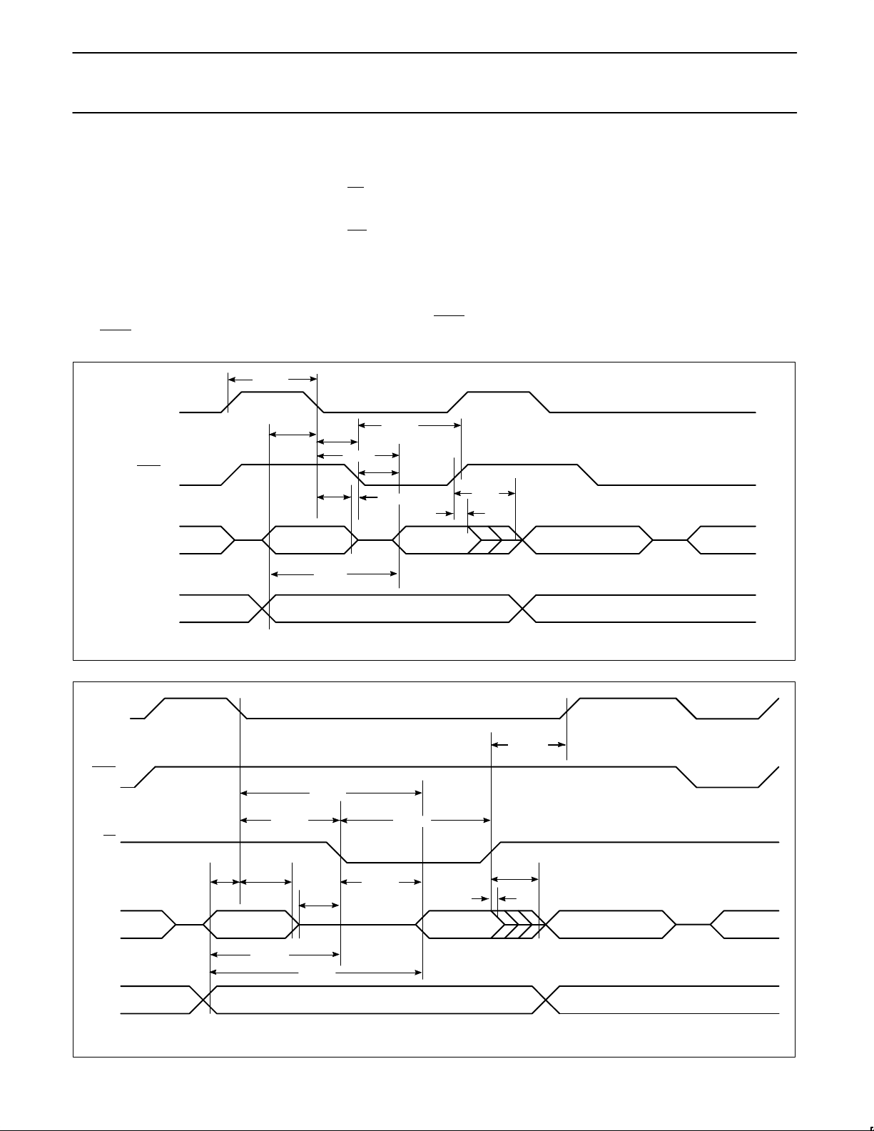
EXPLANATION OF THE AC SYMBOLS
Each timing symbol has five characters. The
first character is always ‘t’ (= time). The other
characters, depending on their positions,
indicate the name of a signal or the logical
status of that signal. The designations are:
A – Address
C – Clock
D – Input data
H – Logic level high
I – Instruction (program memory contents)
L – Logic level low, or ALE
P – PSEN
Q – Output data
R – RD
signal
t – Time
V – Valid
W – WR
signal
X – No longer a valid logic level
Z – Float
Examples: t
AVLL
= Time for address valid
to ALE low.
t
LLPL
= Time for ALE low
to PSEN
low.
t
PXIZ
Figure 3. External Program Memory Read Cycle
ALE
PSEN
PORT 0
PORT 2
A8–A15 A8–A15
A0–A7 A0–A7
t
AVLL
t
PXIX
t
LLAX
INSTR IN
t
PLIV
t
LHLL
t
PLPH
t
LLIV
t
PLAZ
t
LLPL
t
AVIV
ALE
PSEN
PORT 0
PORT 2
Figure 4. External Data Memory Read Cycle
RD
A0–A7
FROM RI OR DPL
DATA IN A0–A7 FROM PCL INSTR IN
P2.0–P2.7 OR A8–A15 FROM DPH A8–A15 FROM PCH
t
WHLH
t
LLDV
t
LLWL
t
RLRH
t
LLAX
t
RLAZ
t
AVLL
t
RHDX
t
RHDZ
t
AVWL
t
AVDV
t
RLDV
Page 14
Philips Semiconductors Preliminary specification
83CE654
CMOS single-chip 8-bit microcontroller with
Electromagnetic Compatibility improvements
1996 Aug 15
14
t
LLAX
ALE
PSEN
PORT 0
PORT 2
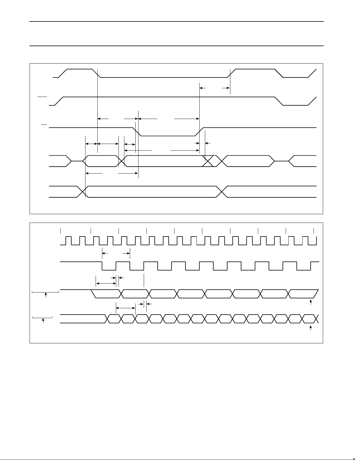
Figure 5. External Data Memory Write Cycle
WR
A0–A7
FROM RI OR DPL
DATA OUT A0–A7 FROM PCL INSTR IN
P2.0–P2.7 OR A8–A15 FROM DPH A8–A15 FROM PCH
t
WHLH
t
LLWL
t
WLWH
t
AVLL
t
AVWL
t
QVWX
t
WHQX
t
DW
0 1 2 3 4 5 6 7 8
INSTRUCTION
ALE
CLOCK
OUTPUT DATA
WRITE TO SBUF
INPUT DATA
CLEAR RI
VALID VALID VALID VALID VALID VALID VALID VALID
SET TI
SET RI
t
XLXL
t
QVXH
t
XHQX
t
XHDX
t
XHDV
Figure 6. Shift Register Mode Timing
Page 15
Philips Semiconductors Preliminary specification
83CE654
CMOS single-chip 8-bit microcontroller with
Electromagnetic Compatibility improvements
1996 Aug 15
15
VDD–0.5
0.45V
0.7V
DD
0.2VDD–0.1
t
CHCL
t
CLCL
t
CLCH
t
CLCX
t
CHCX
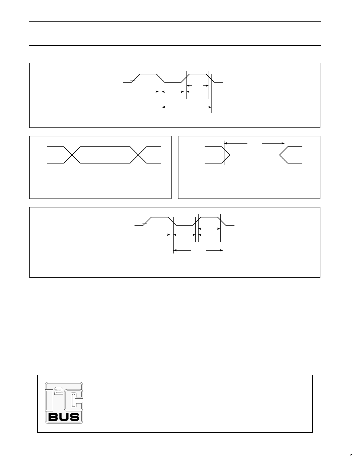
Figure 7. External Clock Drive
2.4V
0.45V
2.0V
0.8V
NOTE:
AC INPUTS DURING TESTING ARE DRIVEN AT 2.4V FOR A LOGIC ‘1’ AND 0.45V
FOR A LOGIC ‘0’. TIMING MEASUREMENTS ARE MADE AT 2.0V FOR A LOGIC ‘1’
AND 0.8V FOR A LOGIC ‘0’.
Figure 8. AC Testing Input/Output
NOTE:
THE FLOAT STATE IS DEFINED AS THE POINT AT WHICH A PORT 0 PIN SINKS
3.2MA OR SOURCES 400µS AT THE VOLTAGE TEST LEVELS.
Figure 9. Float Waveform
2.4V
0.45V
2.0V
0.8V
FLOAT
2.0V
0.8V
VDD–0.5
0.45V
0.7V
DD
0.2VDD–0.1
t
CHCL
t
CLCL
t
CLCH
t
CLCX
t
CHCX
Figure 10. Clock Signal Waveform for IDD Tests in Active and Idle Modes
t
CLCH
= t
CHCL
= 5ns
Purchase of Philips I2C components conveys a license under the Philips’ I2C patent
to use the components in the I
2
C system provided the system conforms to the
I
2
C specifications defined by Philips. This specification can be ordered using the
code 9398 393 40011.
Page 16
Philips Semiconductors Preliminary specification
83CE654
CMOS single-chip 8-bit microcontroller with
Electromagnetic Compatibility improvements
1996 Aug 15
16
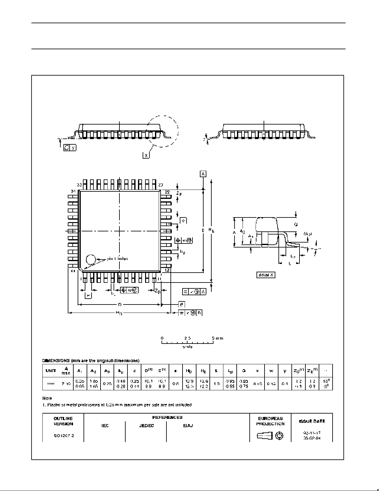
QFP44: plastic quad flat package; 44 leads (lead length 1.3 mm); body 10 x 10 x 1.75 mm SOT307-2
Page 17

Philips Semiconductors Preliminary specification
83CE654
CMOS single-chip 8-bit microcontroller with
Electromagnetic Compatibility improvements
1996 Aug 15
18
Philips Semiconductors and Philips Electronics North America Corporation reserve the right to make changes, without notice, in the products,
including circuits, standard cells, and/or software, described or contained herein in order to improve design and/or performance. Philips
Semiconductors assumes no responsibility or liability for the use of any of these products, conveys no license or title under any patent, copyright,
or mask work right to these products, and makes no representations or warranties that these products are free from patent, copyright, or mask
work right infringement, unless otherwise specified. Applications that are described herein for any of these products are for illustrative purposes
only. Philips Semiconductors makes no representation or warranty that such applications will be suitable for the specified use without further testing
or modification.
LIFE SUPPORT APPLICATIONS
Philips Semiconductors and Philips Electronics North America Corporation Products are not designed for use in life support appliances, devices,
or systems where malfunction of a Philips Semiconductors and Philips Electronics North America Corporation Product can reasonably be expected
to result in a personal injury. Philips Semiconductors and Philips Electronics North America Corporation customers using or selling Philips
Semiconductors and Philips Electronics North America Corporation Products for use in such applications do so at their own risk and agree to fully
indemnify Philips Semiconductors and Philips Electronics North America Corporation for any damages resulting from such improper use or sale.
This data sheet contains preliminary data, and supplementary data will be published at a later date. Philips
Semiconductors reserves the right to make changes at any time without notice in order to improve design
and supply the best possible product.
Philips Semiconductors
811 East Arques Avenue
P.O. Box 3409
Sunnyvale, California 94088–3409
Telephone 800-234-7381
DEFINITIONS
Data Sheet Identification Product Status Definition
Objective Specification
Preliminary Specification
Product Specification
Formative or in Design
Preproduction Product
Full Production
This data sheet contains the design target or goal specifications for product development. Specifications
may change in any manner without notice.
This data sheet contains Final Specifications. Philips Semiconductors reserves the right to make changes
at any time without notice, in order to improve design and supply the best possible product.
Philips Semiconductors and Philips Electronics North America Corporation
register eligible circuits under the Semiconductor Chip Protection Act.
Copyright Philips Electronics North America Corporation 1996
All rights reserved. Printed in U.S.A.
 Loading...