

Page 1
LM137HV/LM337HV
3-Terminal Adjustable Negative Regulators
(High Voltage)
General Description
The LM137HV/LM337HV are adjustable 3-terminal negative
voltage regulators capable of supplying in excess of −1.5A
over an output voltage range of −1.2V to −47V. These regulators are exceptionally easy to apply, requiring only 2 external resistors to set the output voltage and 1 output capacitor
for frequencycompensation.The circuitdesign has been optimized for excellent regulation and low thermal transients.
Further, the LM137HV series features internal current limiting, thermal shutdown and safe-area compensation, making
them virtually blowout-proof against overloads.
The LM137HV/LM337HV serve a wide variety of applications including local on-card regulation,
programmable-output voltage regulation or precision current
regulation. The LM137HV/LM337HV are ideal complements
to the LM117HV/LM317HV adjustable positive regulators.
Features
n Output voltage adjustable from −1.2V to −47V
n 1.5A output current guaranteed, −55˚C to +150˚C
n Line regulation typically 0.01%/V
n Load regulation typically 0.3
%
n Excellent thermal regulation, 0.002%/W
n 77 dB ripple rejection
n Excellent rejection of thermal transients
n 50 ppm/˚C temperature coefficient
n Temperature-independent current limit
n Internal thermal overload protection
n P
+
Product Enhancement tested
n Standard 3-lead transistor package
n Output short circuit protected
Typical Applications
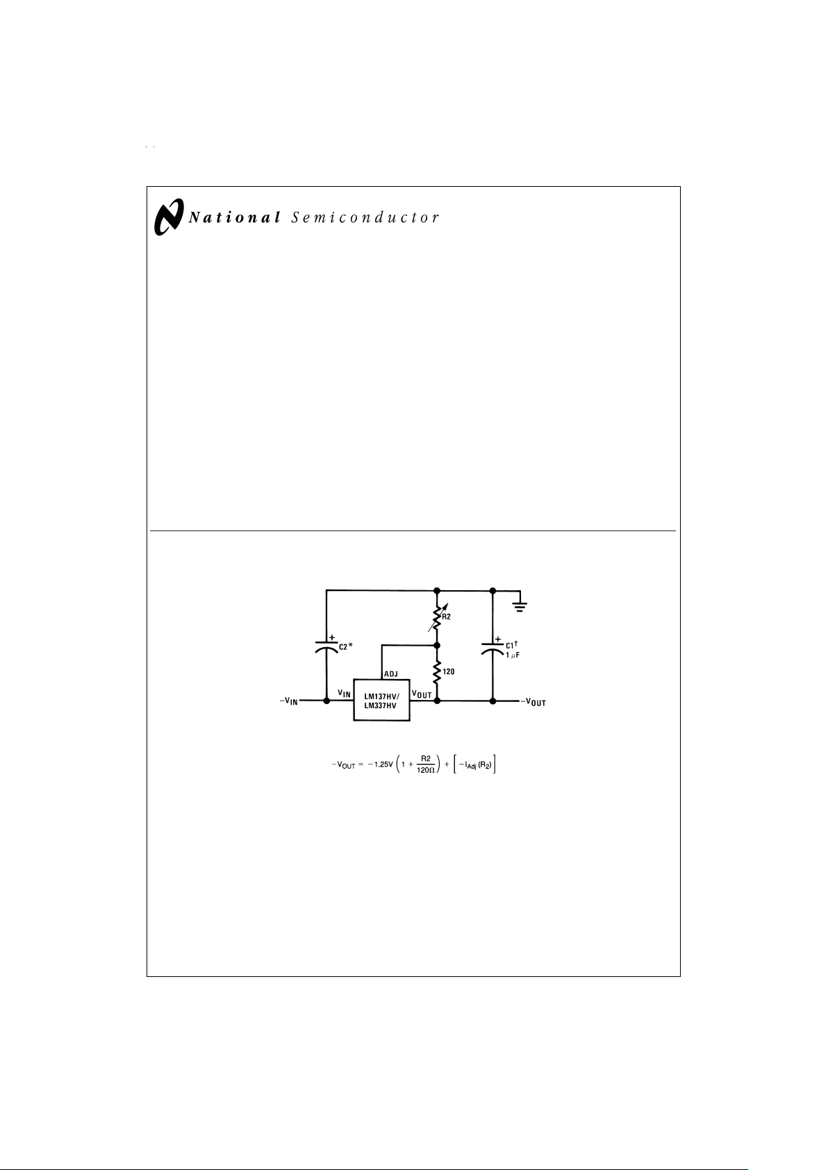
Adjustable Negative Voltage Regulator
DS009066-1
DS009066-25
†
C1=1 µF solid tantalum or 10 µF aluminum electrolytic required for stability.Output capacitors in the range of 1 µF to 1000 µF of aluminum or tantalum
electrolytic are commonly used to provide improved output impedance and rejection of transients.
*
C2=1 µF solid tantalum is required only if regulator is more than 4" from power-supply filter capacitor.
May 1999
LM137HV/LM337HV 3-Terminal Adjustable Negative Regulators (High Voltage)
© 1999 National Semiconductor Corporation DS009066 www.national.com
Page 2
Absolute Maximum Ratings (Note 1)
If Military/Aerospace specified devices are required,
please contactthe National Semiconductor Sales Office/
Distributors for availability and specifications.
(Note 4)
Power Dissipation Internally limited
Input— Output Voltage Differential 50V
Operating Junction Temperature Range
LM137HV −55˚C to +150˚C
LM337HV 0˚C to +125˚C
Storage Temperature −65˚C to +150˚C
Lead Temperature
(Soldering, 10 sec.) 300˚
ESD rating is to be determined.
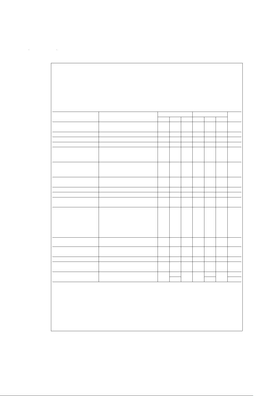
Electrical Characteristics (Note 2)
Parameter Conditions LM137HV LM337HV Units
Min Typ Max Min Typ Max
Line Regulation T
J
=
25˚C, 3V ≤ |V
IN−VOUT
| ≤ 50V, 0.01 0.02 0.01 0.04
%
/V
(Note 3) I
L
=
10 mA
Load Regulation T
J
=
25˚C, 10 mA ≤ I
OUT
≤ I
MAX
0.3 0.5 0.3 1.0
%
Thermal Regulation T
J
=
25˚C, 10 ms Pulse 0.002 0.02 0.003 0.04
%
/W
Adjustment Pin Current 65 100 65 100 µA
Adjustment Pin Current
Change
10 mA ≤ I
L
≤ I
MAX
25 25µA
3.0V ≤ |V
IN−VOUT
| ≤ 50V, 4 6 3 6 µA
T
J
=
25˚
Reference Voltage T
J
=
25˚C, (Note 4) −1.225 −1.250 −1.275 −1.213 −1.250 −1.287 V
3V ≤ |V
IN−VOUT
| ≤ 50V, (Note 4) −1.200 −1.250 −1.300 −1.200 −1.250 −1.300 V
10 mA ≤ I
OUT
≤ I
MAX
,P≤P
MAX
Line Regulation 3V ≤ |VIN−V
OUT
| ≤ 50V, (Note 3) 0.02 0.05 0.02 0.07
%
/V
I
L
=
10 mA
Load Regulation 10 mA ≤ I
OUT
≤ I
MAX
, (Note 3) 0.3 1 0.3 1.5
%
Temperature Stability T
MIN
≤ Tj≤ T
MAX
0.6 0.6
%
Minimum Load Current |V
IN−VOUT
| ≤ 50V 2.5 5 2.5 10 mA
|V
IN−VOUT
| ≤ 10V 1.2 3 1.5 6 mA
Current Limit |V
IN−VOUT
| ≤ 13V
K Package 1.5 2.2 3.2 1.5 2.2 3.5 A
H Package 0.5 0.8 1.6 0.5 0.8 1.8 A
|V
IN−VOUT
|=50V
K Package 0.2 0.4 0.8 0.1 0.4 0.8 A
H Package 0.1 0.17 0.5 0.050 0.17 0.5 A
RMS Output Noise,%of
V
OUT
T
J
=
25˚C, 10 Hz ≤ f ≤ 10 kHz 0.003 0.003
%
Ripple Rejection Ratio V
OUT
=
−10V, f=120 Hz 60 60 dB
C
ADJ
=
10 µF 66 77 66 77 dB
Long-Term Stability T
A
=
125˚C, 1000 Hours 0.3 1 0.3 1
%
Thermal Resistance, Junction H Package 12 15 12 15 ˚C/W
to Case K Package 2.3 3 2.3 3 ˚C/W
Thermal Resistance, Junction
to Ambient
H Package 140 140 ˚C/W
K Package 35 35 ˚C/W
Note 1: “Absolute Maximum Ratings” indicate limits beyond which damage to the device may occur. Operating Ratings indicate conditions for which the device is
functional, but do not guarantee specific performance limits.
Note 2: Unless otherwise specified, these specifications apply: −55˚C ≤ T
j
≤ +150˚C for the LM137HV, 0˚C ≤ Tj≤ +125˚C for the LM337HV; VIN−V
OUT
=
5V; and
I
OUT
=
0.1A for the TO-39 package and I
OUT
=
0.5A for the TO-3 package. Although power dissipation is internally limited, these specifications are applicable for
power dissipations of 2W for the TO-39 and 20W for the TO-3. I
MAX
is 1.5A for the TO-3 package and 0.2A for the TO-39 package.
Note 3: Regulation ismeasured at constantjunction temperature, usingpulse testing with a low duty cycle. Changes in output voltagedue to heatingeffects are covered under the specification for thermal regulations. Load regulation is measured on the output pin at a point
1
⁄8" below the base of the TO-3 and TO-39 packages.
Note 4: Refer to RETS137HVH drawing for LM137HVH or RETS137HVK for LM137HVK military specifications.
www.national.com 2
Page 3
Electrical Characteristics (Note 2) (Continued)
DS009066-2
www.national.com3
Page 4

Thermal Regulation
When power is dissipated in an IC, a temperature gradient
occurs across the IC chip affecting the individual IC circuit
components. Withan IC regulator, this gradientcan be especially severe since power dissipation is large. Thermal regulation is the effect of these temperature gradients on output
voltage (in percentage output change) per Watt of power
change in a specified time. Thermal regulation error is independent of electrical regulation or temperature coefficient,
and occurs within 5 ms to 50 ms after achange in power dissipation. Thermal regulation depends on IC layout as well as
electrical design. The thermal regulation of a voltage regulator is defined as the percentage change of V
OUT
, per Watt,
within the first 10 ms after a step of power is applied. The
LM137HV’s specification is 0.02%/W, max.
In
Figure 1
, a typical LM137HV’s output drifts only 3 mV (or
0.03%of V
OUT
=
−10V) when a 10W pulse is applied for
10 ms. This performance is thus well inside the specification
limit of 0.02%/W x 10W=0.2%max. When the 10W pulse is
ended, the thermal regulation again showsa3mVstep as
the LM137HV chip cools off. Note that the load regulation error of about 8 mV (0.08%) is additional to the thermal regulation error. In
Figure 2
, when the 10W pulse is applied for
100 ms, the output drifts only slightly beyond the drift in the
first 10 ms, and the thermal error stays well within 0.1
%
(10 mV).
Connection Diagram See Physical Dimensions section for further information)
DS009066-3
LM137HV, V
OUT
=
−10V
V
IN−VOUT
=
−40V
I
L
=
0A→0.25A→0A
Vertical sensitivity, 5 mV/div
FIGURE 1.
DS009066-4
LM137HV, V
OUT
=
−10V
V
IN−VOUT
=
−40V
I
L
=
0A→0.25A→0A
Horizontal sensitivity, 20 ms/div
FIGURE 2.
TO-3
Metal Can Package
DS009066-5
Bottom View
Order Number LM137HVK/883, LM137HVK-QMLV, or
SMD
#
7703404
See NS Package Number K02C
Order Number LM337HVK STEEL
See NS Package Number K02A
TO-39
Metal Can Package
DS009066-6
Bottom View
Order Number LM137HVH/883, LM137HVH-QMLV, SMD
#
7703404
or LML337HVH
See NS Package Number H03A
www.national.com 4
Page 5

Typical Applications
Adjustable High Voltage Regulator
DS009066-7
Full output current not available at high input-output voltages
*
The 10 µF capacitors are optional to improve ripple rejection
Current Regulator
DS009066-8
Adjustable Current Regulator
DS009066-9
Negative Regulator with Protection Diodes
DS009066-10
*
When CLis larger than 20 µF, D1 protects the LM137HV in case the input
supply is shorted
**
When C2 is larger than 10 µF and −V
OUT
is larger than −25V, D2
protects the LM137HV is case the output is shorted
High Stability −40V Regulator
DS009066-11
*
Use resistors with good tracking TC<25 ppm/˚C
www.national.com5
Page 6

Typical Performance Characteristics (H and K-STEEL Package)
Load Regulation
DS009066-13
Current Limit
DS009066-14
Adjustment Current
DS009066-15
Dropout Voltage
DS009066-16
Temperature Stability
DS009066-17
Minimum Operating Current
DS009066-18
Ripple Rejection
DS009066-19
Ripple Rejection
DS009066-20
Ripple Rejection
DS009066-21
www.national.com 6
Page 7

Typical Performance Characteristics (H and K-STEEL Package) (Continued)
Output Impedance
DS009066-22
Line Transient Response
DS009066-23
Load Transient Response
DS009066-24
www.national.com7
Page 8

Physical Dimensions inches (millimeters) unless otherwise noted
Metal Can Package (H)
Order Number LM137HVH/883, LM137HVH-QMLV, or LM337HVH
NS Package Number H03A
www.national.com 8
Page 9

Physical Dimensions inches (millimeters) unless otherwise noted (Continued)
Metal Can Package (K)
Order Number LM337HVK STEEL
NS Package Number K02A
Metal Can Package (K)
Mil-Aero Products
Order Number LM137HVK/883, LM137HVK-QMLV, or SMD
#
7703404
NS Package Number K02C
www.national.com9
Page 10

Notes
LIFE SUPPORT POLICY
NATIONAL’S PRODUCTS ARE NOT AUTHORIZED FOR USE AS CRITICAL COMPONENTS IN LIFE SUPPORT
DEVICES OR SYSTEMS WITHOUT THE EXPRESS WRITTEN APPROVAL OF THE PRESIDENT AND GENERAL
COUNSEL OF NATIONAL SEMICONDUCTOR CORPORATION. As used herein:
1. Life support devices or systems are devices or
systems which, (a) are intended for surgical implant
into the body, or (b) support or sustain life, and
whose failure to perform when properly used in
accordance with instructions for use provided in the
labeling, can be reasonably expected to result in a
significant injury to the user.
2. A critical component is any component of a life
support device or system whose failure to perform
can be reasonably expected to cause the failure of
the life support device or system, or to affect its
safety or effectiveness.
National Semiconductor
Corporation
Americas
Tel: 1-800-272-9959
Fax: 1-800-737-7018
Email: support@nsc.com
National Semiconductor
Europe
Fax: +49 (0) 1 80-530 85 86
Email: europe.support@nsc.com
Deutsch Tel: +49 (0) 1 80-530 85 85
English Tel: +49 (0) 1 80-532 78 32
Français Tel: +49 (0) 1 80-532 93 58
Italiano Tel: +49 (0) 1 80-534 16 80
National Semiconductor
Asia Pacific Customer
Response Group
Tel: 65-2544466
Fax: 65-2504466
Email: sea.support@nsc.com
National Semiconductor
Japan Ltd.
Tel: 81-3-5639-7560
Fax: 81-3-5639-7507
www.national.com
LM137HV/LM337HV 3-Terminal Adjustable Negative Regulators (High Voltage)
National does not assume any responsibility for use of any circuitry described, no circuit patent licenses are implied and National reserves the right at any time without notice to change said circuitry and specifications.
 Loading...