

Page 1
DATA SH EET
Product specification
File under Integrated Circuits, IC06
September 1993
INTEGRATED CIRCUITS
74HC/HCT245
Octal bus transceiver; 3-state
For a complete data sheet, please also download:
•The IC06 74HC/HCT/HCU/HCMOS Logic Family Specifications
•The IC06 74HC/HCT/HCU/HCMOS Logic Package Information
•The IC06 74HC/HCT/HCU/HCMOS Logic Package Outlines
Page 2
September 1993 2
Philips Semiconductors Product specification
Octal bus transceiver; 3-state 74HC/HCT245
FEATURES
• Octal bidirectional bus interface
• Non-inverting 3-state outputs
• Output capability: bus driver
• ICC category: MSI
GENERAL DESCRIPTIONS
The 74HC/HCT245 are high-speed Si-gate CMOS devices
and are pin compatible with low power Schottky TTL
(LSTTL). They are specified in compliance with JEDEC
standard no. 7A.
The 74HC/HCT245 are octal transceivers featuring
non-inverting 3-state bus compatible outputs in both send
and receive directions. The “245” features an output
enable (OE) input for easy cascading and a send/receive
(DIR) for direction control. OE controls the outputs so that
the buses are effectively isolated. The “245” is similar to
the “640” but has true (non-inverting) outputs.
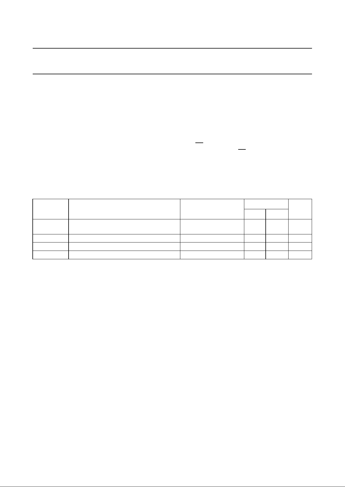
QUICK REFERENCE DATA
GND = 0 V; T
amb
=25°C; tr=tf= 6 ns
Notes
1. C
PD
is used to determine the dynamic power dissipation (PD in µW):
PD=CPD× V
CC
2
× fi+∑ (CL× V
CC
2
× fo) where:
fi= input frequency in MHz
fo= output frequency in MHz
∑ (CL× V
CC
2
× fo) = sum of outputs
CL= output load capacitance in pF
VCC= supply voltage in V
2. For HC the condition is VI= GND to V
CC
For HCT the condition is VI= GND to VCC− 1.5 V
ORDERING INFORMATION
See
“74HC/HCT/HCU/HCMOS Logic Package Information”
.
SYMBOL PARAMETER CONDITIONS
TYPICAL
UNIT
HC HCT
t
PHL
/ t
PLH
propagation delay
An to Bn;Bn to A
n
CL= 15 pF; VCC=5V 7 10 ns
C
I
input capacitance 3.5 3.5 pF
C
I/O
input/output capacitance 10 10 pF
C
PD
power dissipation capacitance per transceiver notes 1 and 2 30 30 pF
Page 3
September 1993 3
Philips Semiconductors Product specification
Octal bus transceiver; 3-state 74HC/HCT245
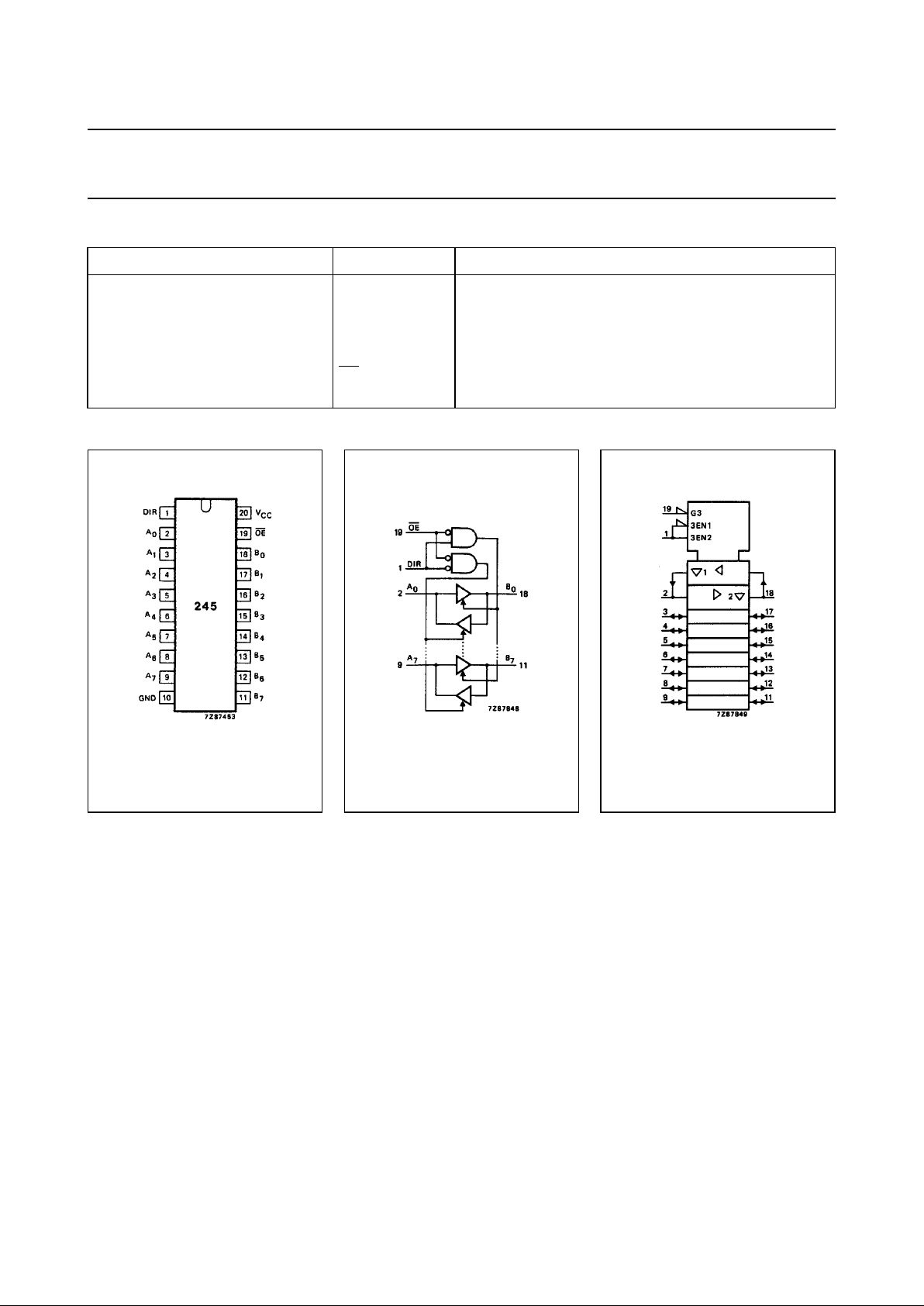
PIN DESCRIPTION
PIN NO. SYMBOL NAME AND FUNCTION
1 DIR direction control
2, 3, 4, 5, 6, 7, 8, 9 A
0
to A
7
data inputs/outputs
10 GND ground (0 V)
18, 17, 16, 15, 14, 13, 12, 11 B
0
to B
7
data inputs/outputs
19
OE output enable input (active LOW)
20 V
CC
positive supply voltage
Fig.1 Pin configuration. Fig.2 Logic symbol. Fig.3 IEC logic symbol.
Page 4
September 1993 4
Philips Semiconductors Product specification
Octal bus transceiver; 3-state 74HC/HCT245
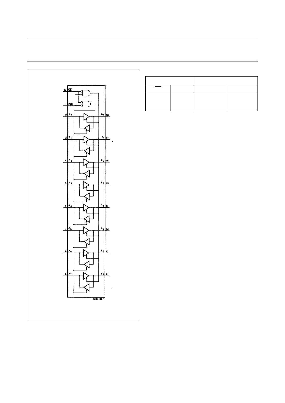
Fig.4 Functional diagram.
FUNCTION TABLE
Notes
1. H = HIGH voltage level
L = LOW voltage level
X = don’t care
Z = high impedance OFF-state
INPUTS INPUTS/OUTPUTS
OE DIR A
n
B
n
L
L
H
L
H
X
A=B
inputs
Z
inputs
B=A
Z
Page 5
September 1993 5
Philips Semiconductors Product specification
Octal bus transceiver; 3-state 74HC/HCT245
DC CHARACTERISTICS FOR 74HC
For the DC characteristics see
“74HC/HCT/HCU/HCMOS Logic Family Specifications”
.
Output capability: bus driver
ICC category: MSI
AC CHARACTERISTICS FOR 74HC
GND = 0 V; t
r=tf
= 6 ns; CL=50pF
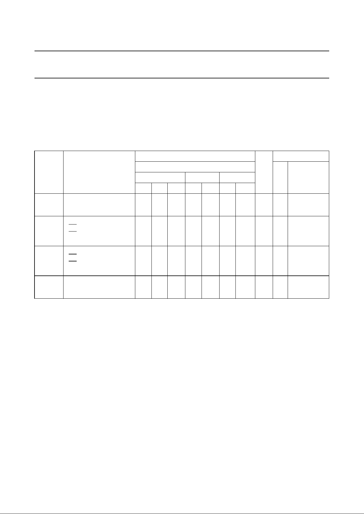
SYMBOL PARAMETER
T
amb
(°C)
UNIT
TEST CONDITIONS
74HC
V
CC
(V)
WAVEFORMS
+25 −40 to +85 −40 to +125
min. typ. max. min. max. min. max.
t
PHL
/ t
PLH
propagation delay
An to B
n;
Bn to A
n
25
9
7
90
18
15
115
23
20
135
27
23
ns 2.0
4.5
6.0
Fig.5
t
PZH
/ t
PZL
3-state output enable time
OE to A
n;
OE to B
n
signalname DIR
30
11
9
150
30
26
190
38
33
225
45
38
ns
2.0
4.5
6.0
Fig.6
t
PHZ
/ t
PLZ
3-state output disable time
OE to A
n;
OE to B
n
signalname DIR
41
15
12
150
30
26
190
38
33
225
45
38
ns 2.0
4.5
6.0
Fig.6
t
THL
/ t
TLH
output transition time 14
5
4
60
12
10
75
15
13
90
18
15
ns 2.0
4.5
6.0
Fig.5
Page 6
September 1993 6
Philips Semiconductors Product specification
Octal bus transceiver; 3-state 74HC/HCT245
DC CHARACTERISTICS FOR 74HCT
For the DC characteristics see
“74HC/HCT/HCU/HCMOS Logic Family Specifications”
.
Output capability: bus driver
ICC category: MSI
Note to HCT types
The value of additional quiescent supply current (∆I
CC
) for a unit load of 1 is given in the family specifications.
To determine ∆ICC per input, multiply this value by the unit load coefficient shown in the table below.
AC CHARACTERISTICS FOR 74HCT
GND = 0 V; tr=tf= 6 ns; CL=50pF
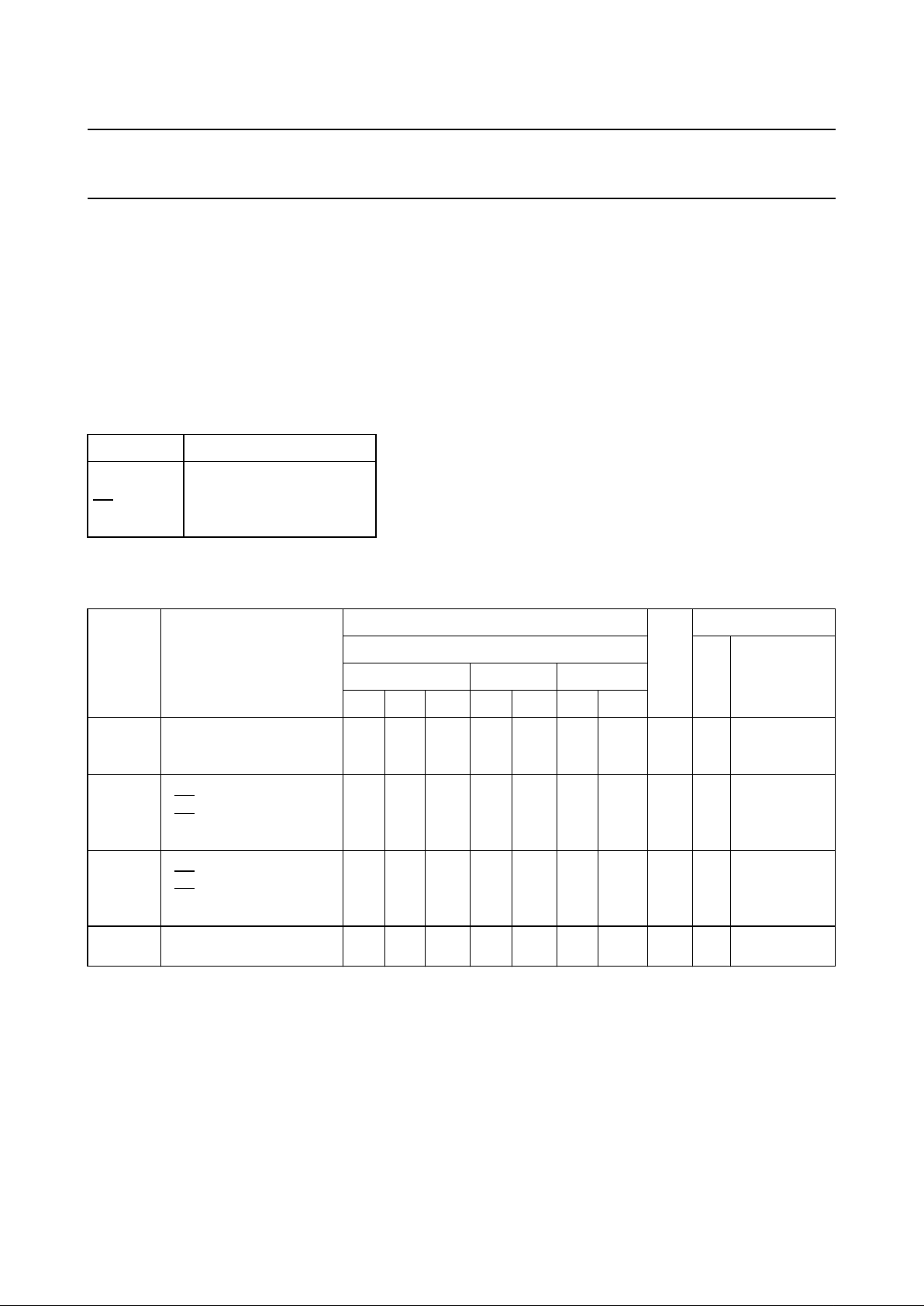
INPUT UNIT LOAD COEFFICIENT
A
n
B
n
OE
DIR
0.40
0.40
1.50
0.90
SYMBOL PARAMETER
T
amb
(°C)
UNIT
TEST CONDITIONS
74HCT
V
CC
(V)
WAVEFORMS
+25 −40 to +85 −40 to +125
min. typ. max. min. max. min. max.
t
PHL
/ t
PLH
propagation delay
An to B
n;
Bn to A
n
12 22 28 33 ns 4.5 Fig.5
t
PZH
/ t
PZL
3-state output enable time
OE to A
n;
OE to B
n
signalname DIR
16 30 38 45 ns 4.5 Fig.6
t
PHZ
/ t
PLZ
3-state output disable time
OE to A
n;
OE to B
n
signalname DIR
16 30 38 45 ns 4.5 Fig.6
t
THL
/ t
TLH
output transition time 5 12 15 18 ns 4.5 Fig.5
Page 7
September 1993 7
Philips Semiconductors Product specification
Octal bus transceiver; 3-state 74HC/HCT245
AC WAVEFORMS
PACKAGE OUTLINES
See
“74HC/HCT/HCU/HCMOS Logic Package Outlines”
.
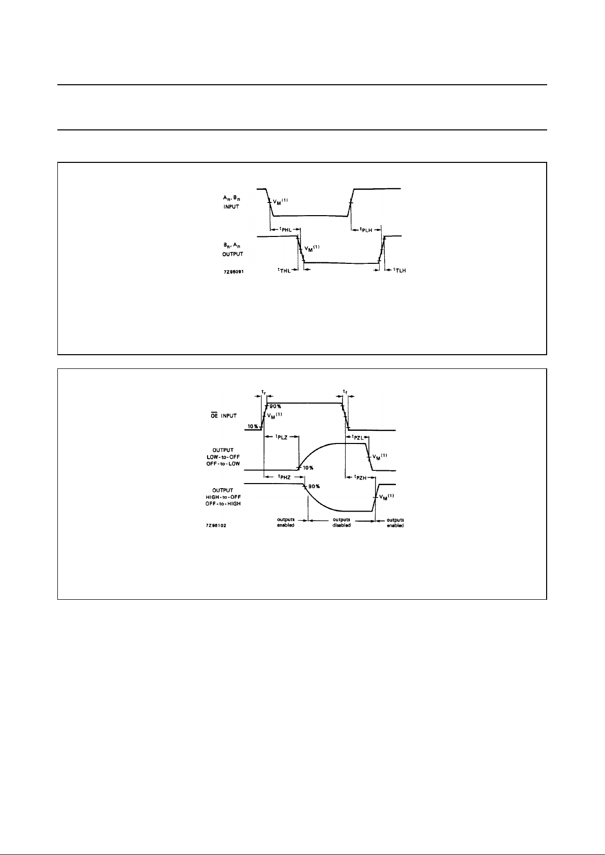
Fig.5 Waveforms showing the input (An, Bn) to output (Bn, An) propagation delays and the output transition times.
(1) HC : VM= 50%; VI= GND to VCC.
HCT : V
M
= 1.3 V; VI= GND to 3 V.
Fig.6 Waveforms showing the 3-state enable and disable times.
(1) HC : VM= 50%; VI= GND to VCC.
HCT : V
M
= 1.3 V; VI= GND to 3 V.
 Loading...