

Page 1
74F401
CRC Generator/Checker
74F401 CRC Generator/Checker
April 1988
Revised August 1999
General Description
The 74F401 Cycle Red undancy Check (CRC) Generato r/
Checker provides an advance d tool for implementing the
most widely used er ror detection scheme in serial digital
data handling systems. A 3-bit contr ol inpu t sele cts on e-o feight generator polynomials. The list of polynomials
includes CRC-16 and CRC-CCITT as well as their reciprocals (reverse polynomials). Automatic right justification is
incorporated for polynom ial s o f deg ree l ess th an 1 6. Sep arate clear and preset inpu ts are provided for floppy disk
and other applicat ions. Th e Error ou tput ind icates wheth er
or not a transmission error has occurred. An other control
input inhibits feedback during check word transmission.
The 74F401 is fully compatible with all TTL families.
Features
■ Eight selectable polynomials
■ Error indicator
■ Separate preset and clear controls
■ Automatic right justification
■ Fully compatible with all TTL logic families
■ 14-pin package
■ 9401 equivalent
■ Typical applications:
Floppy and other disk storage systems
Digital cassette and cartridge systems
Data communication systems
Ordering Code:
Order Number Package Number Package Description
74F401SC M14A 14-Lead Small Outline Integrated Circuit (SOIC), JEDEC MS-120, 0.150 Narrow
74F401PC N14A 14-Lead Plastic Dual-In-Line Package (PDIP), JEDEC MS-001, 0.300 Wide
Devices also availab le in Tape and Reel. Specify by appending th e s uffix let t er “X” to the ordering cod e.
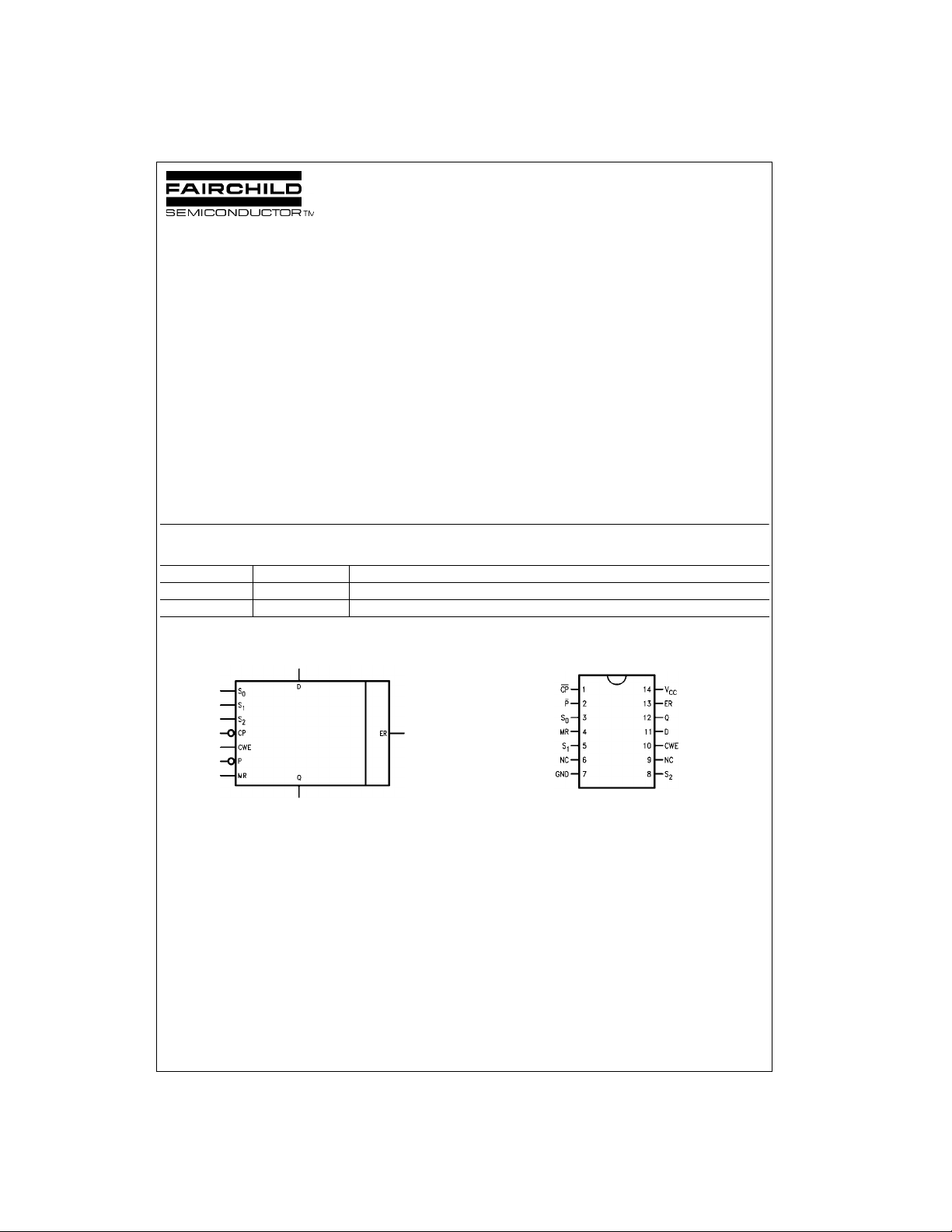
Logic Symbol Connection Diagram
© 1999 Fairchild Semiconductor Corporation DS009534 www.fairchildsemi.com
Page 2
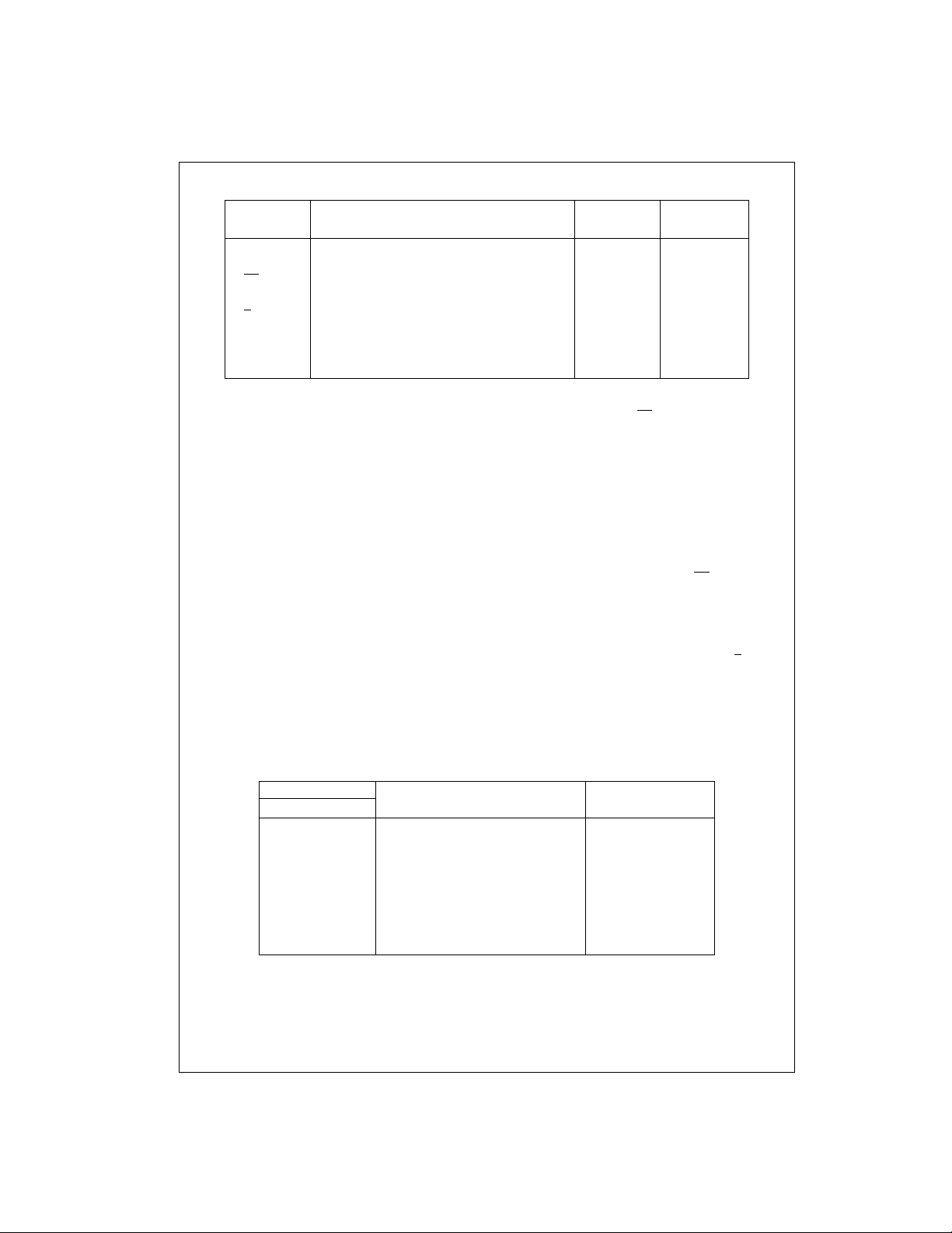
Unit Loading/Fan Out
74F401
Pin Names Description
S0–S
2
Polynomial Select Inputs 1.0/1.0 20 µA/−0.6 mA
D Data Input 1.0/1.0 20 µA/−0.6 mA
CP
Clock Input (Operates on HIGH-to-LOW Transition) 1.0/1.0 20 µA/−0.6 mA
CWE Check Word Enable Input 1.0/1.0 20 µA/−0.6 mA
P
Preset (Active LOW) Input 1.0/1.0 20 µA/−0.6 mA
MR Master Reset (Active HIGH) Input 1.0/1.0 20 µA/−0.6 mA
Q Data Output 50/33.3 −1 mA/20 mA
ER Error Output 50/33.3 −1 mA/20 mA
Functional Description
The 74F401 is a 16-bit progr ammable device w hich operates on serial data streams and provides a means of
detecting transmission er rors. Cyclic encod ing and decoding schemes for err or detection are based on poly nomial
manipulation in m odulo arithmetic . For encoding , the data
stream (message polynomial) is divided by a selected polynomial. This division results in a remainder which is
appended to the messa ge as check bits. For err or checking, the bit stream conta ining both data and check bits is
divided by the same select ed polynomial. If there are no
detectable errors, this di vision results in a ze ro remainder.
Although it is possible to choose many generating polynomials of a given degree, standards exist that specify a
small number of useful polynomials. The 74F401 implements the polynomials listed in Table 1 by applying the
appropriate logic levels to the select pins S
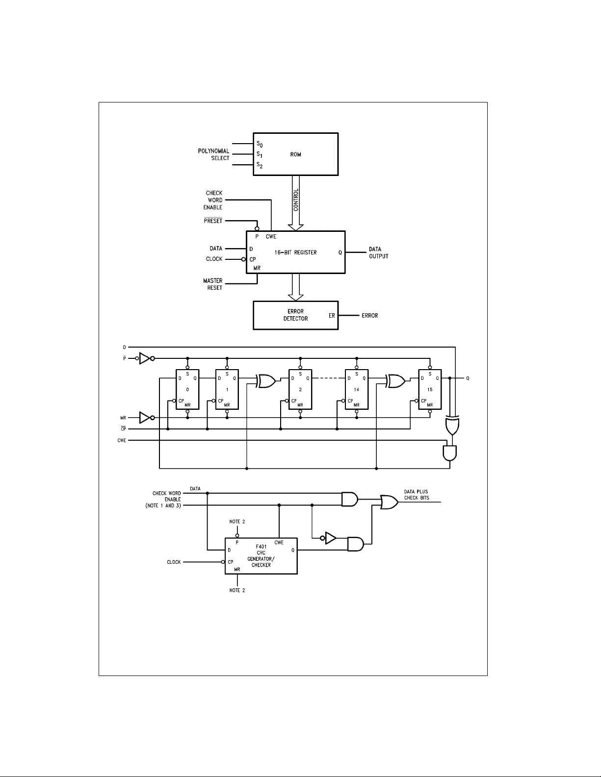
The 74F401 consists of a 16-bit register, a Read Only
Memory (ROM) and associated control circuitry as show n
in the block diagram. The polynomial control code presented at inputs S
, S1 and S2 is decoded by the ROM,
0
selecting the desired polynomial by establishing shift mode
operation on the register with Exclusive OR gates at appropriate inputs. To generate the check bits, the data stream is
entered via the Da ta inputs (D), using the HIGH- to-LOW
0, S1
and S2.
U.L.
HIGH/LOW
transition of the Clock inpu t (CP
Input I
IH/IIL
Output I
OH/IOL
). This data is gate d with
the most significant output (Q ) of the register, and controls
the Exclusive OR gates Figu re 1. Th e Ch eck Word Enabl e
(CWE) must be held HIGH wh i le th e da ta i s b ei ng en ter ed.
After the last data bit is entered, the CWE is brou ght LOW
and the check bits are shifted out of the register and
appended to the data bits using external gating Figure 2.
To check an incoming messa ge for errors, both the data
and check bits are e ntered through the D input w ith the
CWE input held HIGH. The 74F4 01 is not in the data path,
but only monitors the message. The Error Output becomes
valid after the last check bit has been entered into the
74F401 by a HIGH-to-LOW tra nsition of CP
. If no detectable errors have occurred during the data transmission, the
resultant internal reg ister bits are all LOW and the Error
Output (ER) is LOW. If a detectable error has occurred, ER
is HIGH.
A HIGH on the Master Reset input (MR) asynchronously
clears the register. A LOW on the Preset input (P
) asynchronously sets the entire register if the control code inputs
specify a 16-bit polynomial; in the case of 12- or 8-bit check
polynomials only th e most significa nt 12 or 8 regist er bits
are set and the remaining bits are cleared.
TABLE 1.
Select Code
S
2
S
S
1
0
Polynomial Remarks
LLLX16 + X15 + X2 + 1 CRC-16
16
LLHX
LHLX
LHHX
HLLX
HLHX
HHLX
HHHX
+ X14 + X + 1 CRC-16 REVERSE
16
+ X15 + X13 + X7 + X4 + X2 + X1 + 1
12
+ X11 + X3 + X2 + X + 1 CRC-12
8
+ X7 + X5 + X4 + X + 1
8
+ 1 LRC-8
16
+ X12 + X5 + 1 CRC-CCITT
16
+ X11 + X4 + 1 CRC-CCITT REVERSE
www.fairchildsemi.com 2
Page 3
Block Diagram
74F401
FIGURE 1. Equivalent Circuit for X16 + X15 + X2 + 1
Note 1: Check word En able is HIGH while data is being clocked, LOW while transmission of ch ec k bit s .
Note 2: 74F401 must be reset or preset before each computation.
Note 3: CRC check bits are generated and appended to data bits.
FIGURE 2. Check Word Generation
3 www.fairchildsemi.com
Page 4
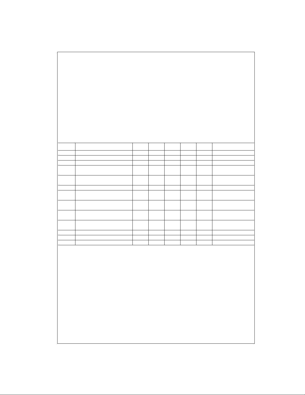
Absolute Maximum Ratings(Note 4) Recommended Operating
Storage Temperature −65°C to +150°C
74F401
Ambient Temperature under Bias −55°C to +125°C
Junction Temperature under Bias −55°C to +150°C
Pin Potential to Ground Pin −0.5V to +7.0V
V
CC
Input Voltage (Note 5) −0.5V to +7.0V
Input Current (Note 5) −30 mA to +5.0 mA
Voltage Applied to Output
in HIGH State (with V
CC
= 0V)
Standard Output −0.5V to V
3-STATE Output −0.5V to +5.5V
Current Applied to Output
in LOW State (Max) twice the rated I
OL
Conditions
Free Air Ambient Temperature 0°C to +70°C
Supply Voltage +4.5V to +5.5V
Note 4: Absolute maximum ratings are values beyond which the device
may be damaged or have its useful life impaired. Functional operation
CC
under these conditi ons is not implied.
Note 5: Either voltage limit or curren t limit is sufficient to protect in put s .
(mA)
DC Electrical Characteristics
Symbol Parameter Min Typ Max Units
V
V
V
V
V
I
I
I
V
I
I
I
I
IH
IL
CD
OH
OL
IH
BVI
CEX
ID
OD
IL
OS
CCH
Input HIGH Voltage 2.0 V Recognized as a HIGH Signal
Input LOW Voltage 0.8 V Recognized as a LOW Signal
Input Clamp Diode Voltage −1.2 V Min IIN = −18 mA
Output HIGH 10% V
Voltage 5% V
Output LOW
Voltage
Input HIGH Current 5.0 µAMaxVIN = 2.7V
Input HIGH Current
Breakdown Test
Output HIGH
Leakage Current
Input Leakage
Test All Other Pins Grounded
Output Leakage
Circuit Current All Other Pins Grounded
Input LOW Current −0.6 mA Max VIN = 0.5V
Output Short-Circuit Current −60 −150 mA Max V
Power Supply Current 70 105 mA Max VO = HIGH
10% V
2.5
CC
2.7 IOH = −1 mA
CC
CC
4.75 V 0.0
0.5 V Min IOL = 20 mA
7.0 µAMaxVIN = 7.0V
50 µAMaxV
3.75 µA0.0
V
CC
VMin
IOH = −1 mA
OUT
IID = 1.9 µA
V
IOD
OUT
Conditions
= V
CC
= 150 mV
= 0V
www.fairchildsemi.com 4
Page 5
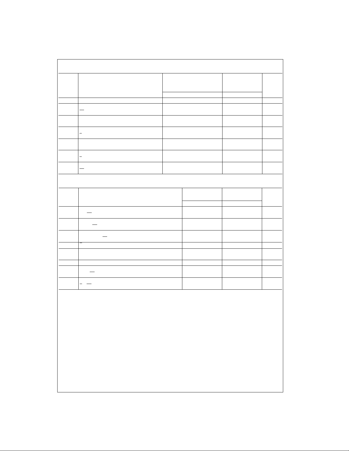
AC Electrical Characteristics
Symbol Parameter
f
t
t
t
t
t
t
t
t
MAX
PLH
PHL
PHL
PLH
PHL
PLH
PLH
PHL
Maximum Clock Frequency 100 85 MHz
Propagation Delay 4.5 11.5 4.5 13.5
CP to Q
Propagation Delay
MR to Q
Propagation Delay
P to Q
Propagation Delay
MR to ER
Propagation Delay
P to ER
Propagation Delay 5.0 13.0 5.0 14.5
CP to ER
TA = +25°CT
VCC = +5.0V VCC = +5.0V
CL = 50 pF CL = 50 pF
Min Typ Max Min Max
4.0 10.0 4.0 11.0
3.0 7.5 3.0 8.0 ns
3.0 8.5 3.0 9.5 ns
3.5 11.0 3.5 12.0 ns
3.0 8.5 3.0 10.0 ns
4.5 11.5 4.5 12.5
= 0°C to +70°C
A
Units
AC Operating Requirements
TA = +25°CT
Symbol Parameter
MinMaxMinMax
tS(H) Set-up Time, HIGH or LOW 5.0 5.5
tS(L)
tS(H) Set-up Time, HIGH or LOW 4.0 4.5
tS(L)
tH(H) Hold Time, HIGH or LOW 2.0 2.0
tH(L)
tW(L) P Pulse Width, LOW 7.0 8.0 ns
tW(H) Clock Pulse Width, 5.0 6.0
tW(L) HIGH or LOW 5.0 6.0
tW(H) MR Pulse Width, HIGH 5.0 5.5 ns
t
REC
t
REC
D to CP
CWE to CP
D and CWE to CP
Recovery Time
MR to CP
Recovery Time
P to CP
5.0 5.5
4.0 4.5
2.0 2.0
4.0 4.5 ns
2.0 2.0 ns
= 0°C to +70°C
A
UnitsVCC = +5.0V VCC = +5.0V
74F401
ns
ns
ns
ns
5 www.fairchildsemi.com
Page 6
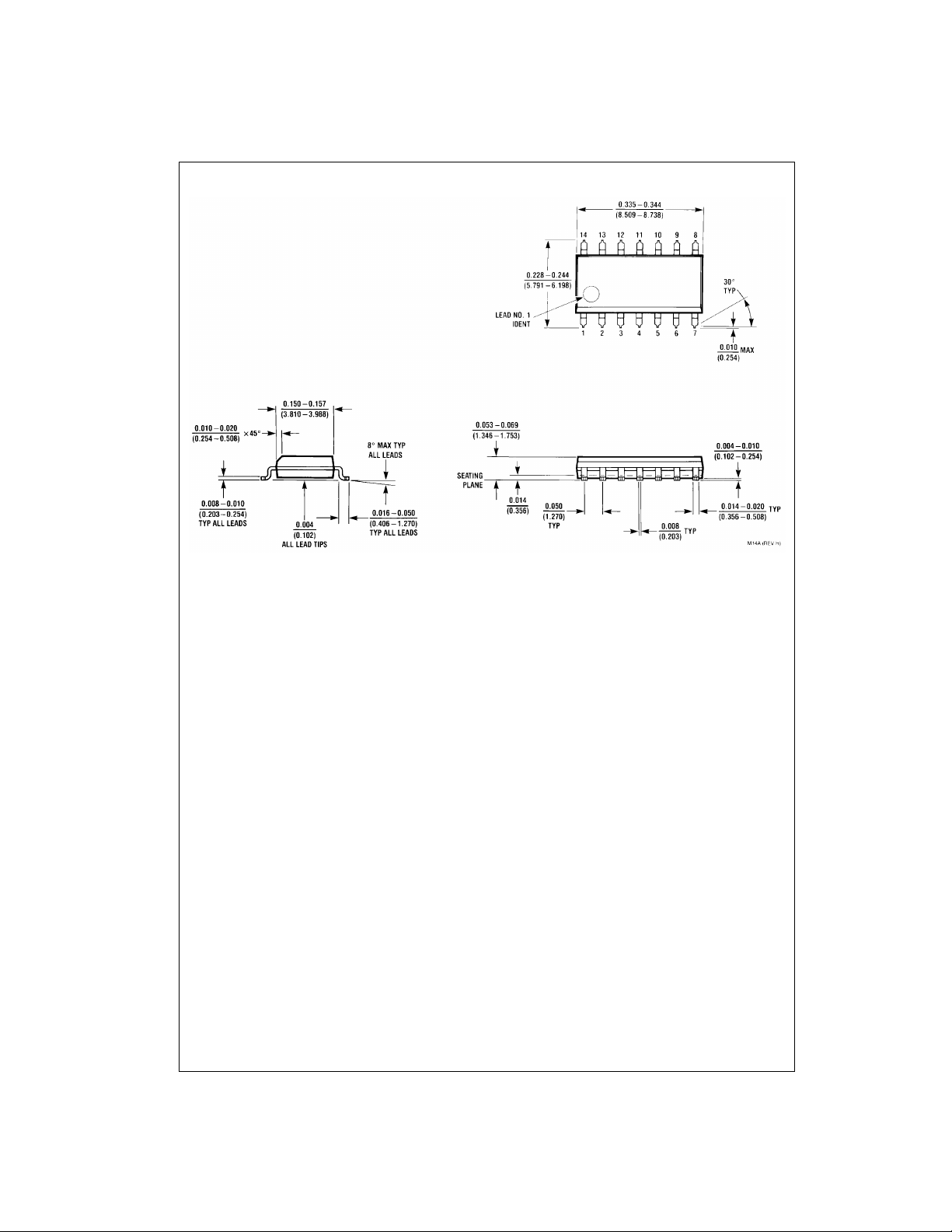
Physical Dimensions inches (millimeters) unless otherwise noted
74F401
14-Lead Small Outline Integrated Circuit (SOIC), JEDEC MS-120, 0.150 Narrow
Package Number M14A
www.fairchildsemi.com 6
Page 7
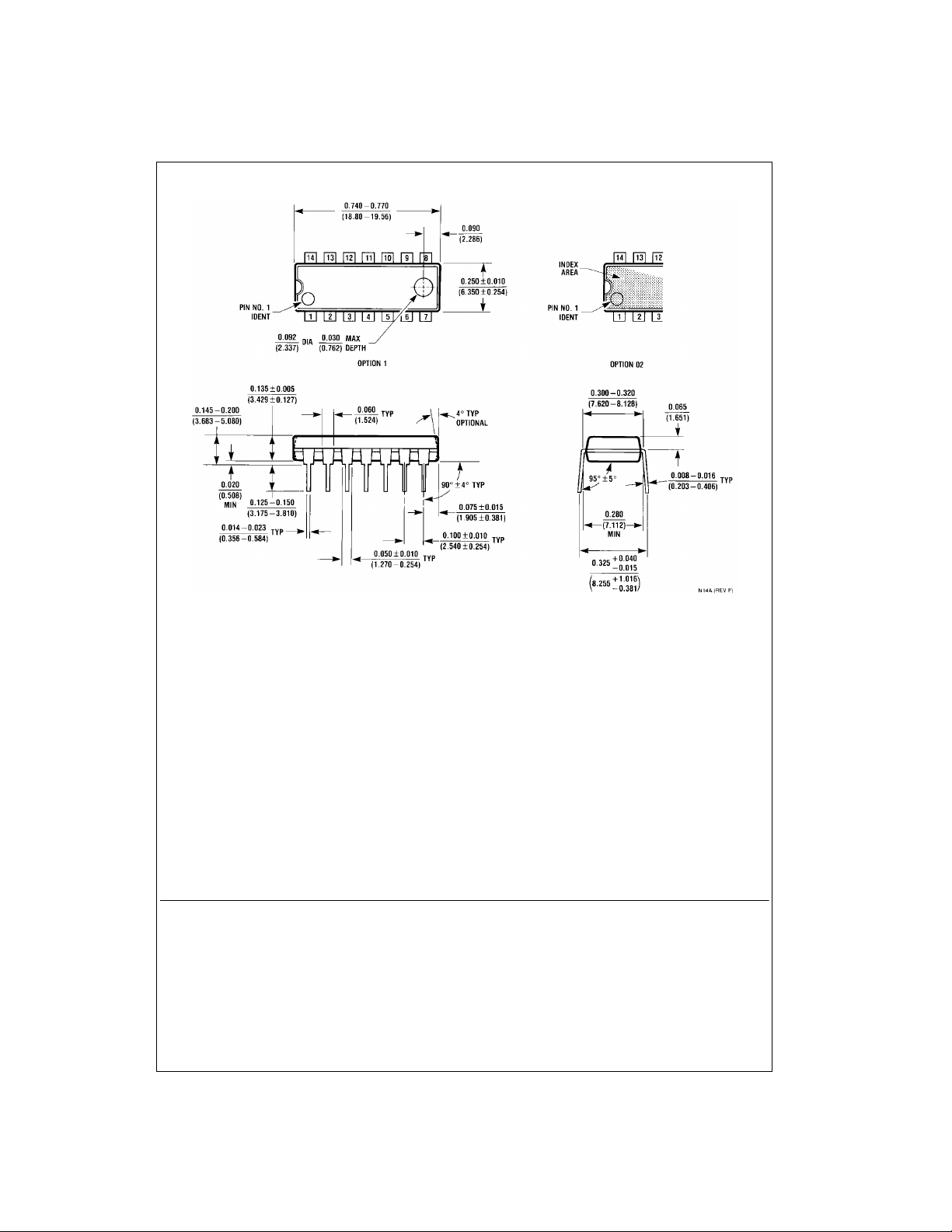
Physical Dimensions inches (millimeters) unless otherwise noted (Continued)
74F401 CRC Generator/Checker
14-Lead Plastic Dual-In-Line Package (PDIP), JEDEC MS-001, 0.300 Wide
Fairchild does not assume any responsibility for use of any circuitry described, no circuit patent license s are implied and
Fairchild reserves the right at any time without notice to change said circuitry and specifications.
LIFE SUPPORT POLICY
FAIRCHILD’S PRODUCTS ARE NOT AUTHORIZED FOR USE AS CRITICAL COMPONENTS IN LIFE SUPPORT
DEVICES OR SYSTEMS WITHOUT THE EXPRESS WRITTEN APPROVAL OF THE PRESIDENT OF FAIRCHILD
SEMICONDUCTOR CORPORATION. As used herein:
1. Life support devices or systems are devices or systems
which, (a) are intended for surgical implant into the
body, or (b) support or sustain life, and (c) whose failure
to perform when properly used in accordance with
instructions for use provide d in the labe l ing, can be re asonably expected to result in a significant injury to the
user.
Package Number N14A
2. A critical componen t in any com ponen t of a life s upport
device or system whose failu re to perform can b e reasonably expected to cause the failure of the life support
device or system, or to affect its safety or effectiveness.
www.fairchildsemi.com
7 www.fairchildsemi.com
 Loading...