

Page 1
April 1988
Revised March 1999
74F192
Up/Down Decade Counter with Separate Up/Down
Clocks
74F192 Up/Down Decade Counter with Separate Up/Down Clocks
General Description
The 74F192 is an u p/down BCD decade (8421) counter.
Separate Count Up and Count Down Clocks ar e use d, a nd
in either counting mode the circuits operate synchronously.
The outputs change stat e synchrono usly with the L OW-toHIGH transitions on the clock inputs.
Separate Terminal Count Up and Terminal Count Down
outputs are used as the clocks for a subsequent stage
without extra logic, thus simplifying multistage counter
designs. Individual preset inputs allow the circuit to be used
as a programmable counter. Both the Parallel Load (PL
and the Master Reset (MR) inputs asynchronously override
the clocks.
Features
■ Guaranteed 4000V mini mum ESD protection
Ordering Code:
Order Number Package Number Package Description
74F192SJ M16D 16-Lead Small Outline Package (SOP), EIAJ TYPE II, 5.3mm Wide
74F192PC N16E 16-Lead Plastic Dual-In-Line Package (PDIP), JEDEC MS-001, 0.300 Wide
Devices also availab le in Tape and Reel. Specify by appending the suffix letter “X” to the ordering code.
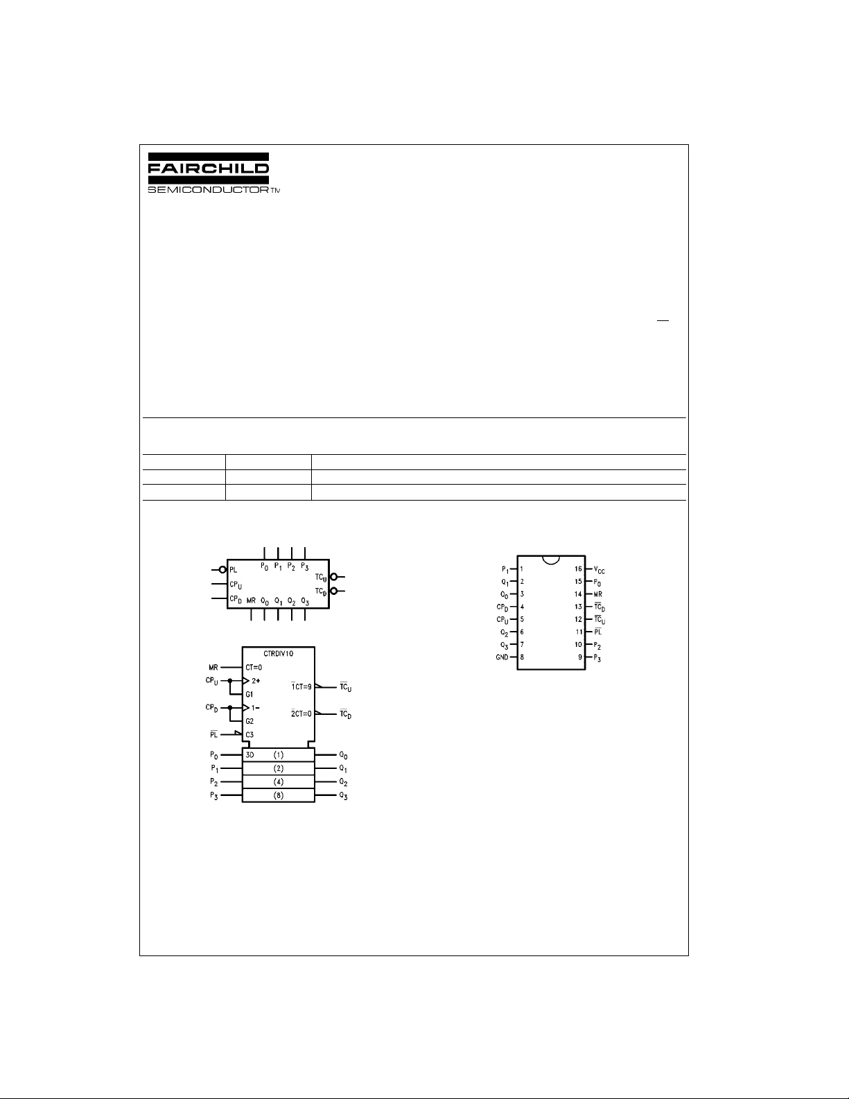
Logic Symbols
IEEE/IEC
Connection Diagram
)
© 1999 Fairchild Semiconductor Corporation DS009496.prf www.fairchildsemi.com
Page 2
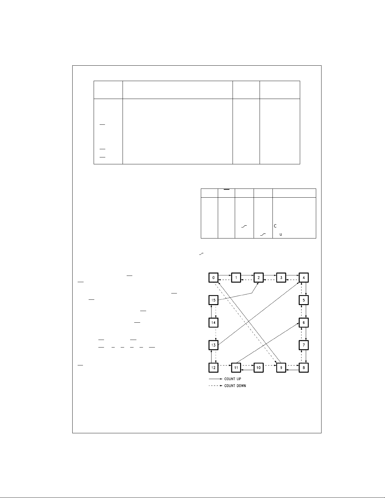
Unit Loading/Fan Out
74F192
Pin Names Description
CP
CP
Count Up Clock Input (Active Rising Edge) 1.0/3.0 20 µA/−1.8 mA
U
Count Down Clock Input (Active Rising Edge) 1.0/3.0 20 µA/−1.8 mA
D
MR Asynchronous Master Reset Input (Active HIGH) 1.0/1.0 20 µA/−0.6 mA
PL
P
Q
TC
TC
0–P3
0–Q3
Asynchronous Parallel Load Input (Active LOW) 1.0/1.0 20 µA/−0.6 mA
Parallel Data Inputs 1.0/1.0 20 µA/−0.6 mA
Flip-Flop Outputs 50/33.3 −1 mA/20 mA
Terminal Count Down (Borrow) Output (Active LOW) 50/33.3 −1 mA/20 mA
D
Terminal Count Up (Carry) Output (Active LOW) 50/33.3 −1 mA/20 mA
U
Functional Description
The 74F192 is an asynchronously presettable decade
counter. It contains four edge-triggered flip-flops, with internal gating and steering logic to provide master reset, individual preset, count up and count down operations.
A LOW-to-HIGH transition on the CP inpu t to each flip-flo p
causes the output to change state. Synchronous switching,
as opposed to ripp le counting, is achieved by dr iving the
steering gates o f all st ages from a com mon Coun t Up line
and a common Count Down line, thereby causing a ll state
changes to be initiated simultaneously. A LOW-to-HIGH
transition on the Count Up input will a dvance the count by
one; a similar transition on the Count Down input will
decrease the count b y one. While cou nting with one cl ock
input, the other sh ould be held HIGH, as indica ted in the
Function Table. Otherwise, the circuit will either count by
twos or not at al l, depending on the st ate of the first flipflop, which cann ot toggle as long as eit her clock input is
LOW.
The Terminal Count Up (TC
) outputs are normally HIGH. When the circuit has
(TC
D
reached the maximum count state 9, the next HIGH-toLOW transition of the Count Up Clock will cause TC
LOW. TC
will stay LOW until CPU goes HIGH aga in, th us
U
effectively repeating the Cou nt Up Clock, but delayed by
two gate delays. Similarly, the TC
when the circuit is in the zero state and the Count Down
Clock goes LOW. Since the TC
waveforms, they can be used as the cl ock input sign als to
the next higher order circuit in a multistage counter.
= Q0 • Q3 • CP
TC
U
TCD = Q0 • Q1 • Q2 • Q3 • CP
The 74F192 has an asynchronous parallel load capability
permitting the counter to be preset. When the Parallel Load
) and the Master Reset ( MR) inputs ar e LOW, informa-
(PL
tion present on the Parallel Data input (P
into the counter and appears on the outputs regardless of
the conditions of the clock inpu ts. A HIGH signal on the
Master Reset input w ill disable the preset gates, ove rride
both clock inputs, and latch each Q output in the LOW
state. If one of t he clock inp uts is LOW du ring and aft er a
reset or load operation, the next LOW-to-HIGH transition of
that clock will be interpreted as a legitimate signal and will
be counted.
) and Terminal Count Down
U
output will go LOW
D
outputs repeat the c lock
U
D
) is loaded
0–P3
to go
U
U.L. Input I
HIGH/LOW Output IOH/I
Function Table
MR PL CP
H X X X Reset (Asyn.)
L L X X Preset (Asyn.)
L H H H No Change
LH
LHH
H = HIGH Voltage Level
L = LOW Voltage Level
X = Immaterial
= LOW-to-HIGH Clock Transition
U
CP
D
H Count Up
Count Down
State Diagram
IH/IIL
OL
Mode
www.fairchildsemi.com 2
Page 3
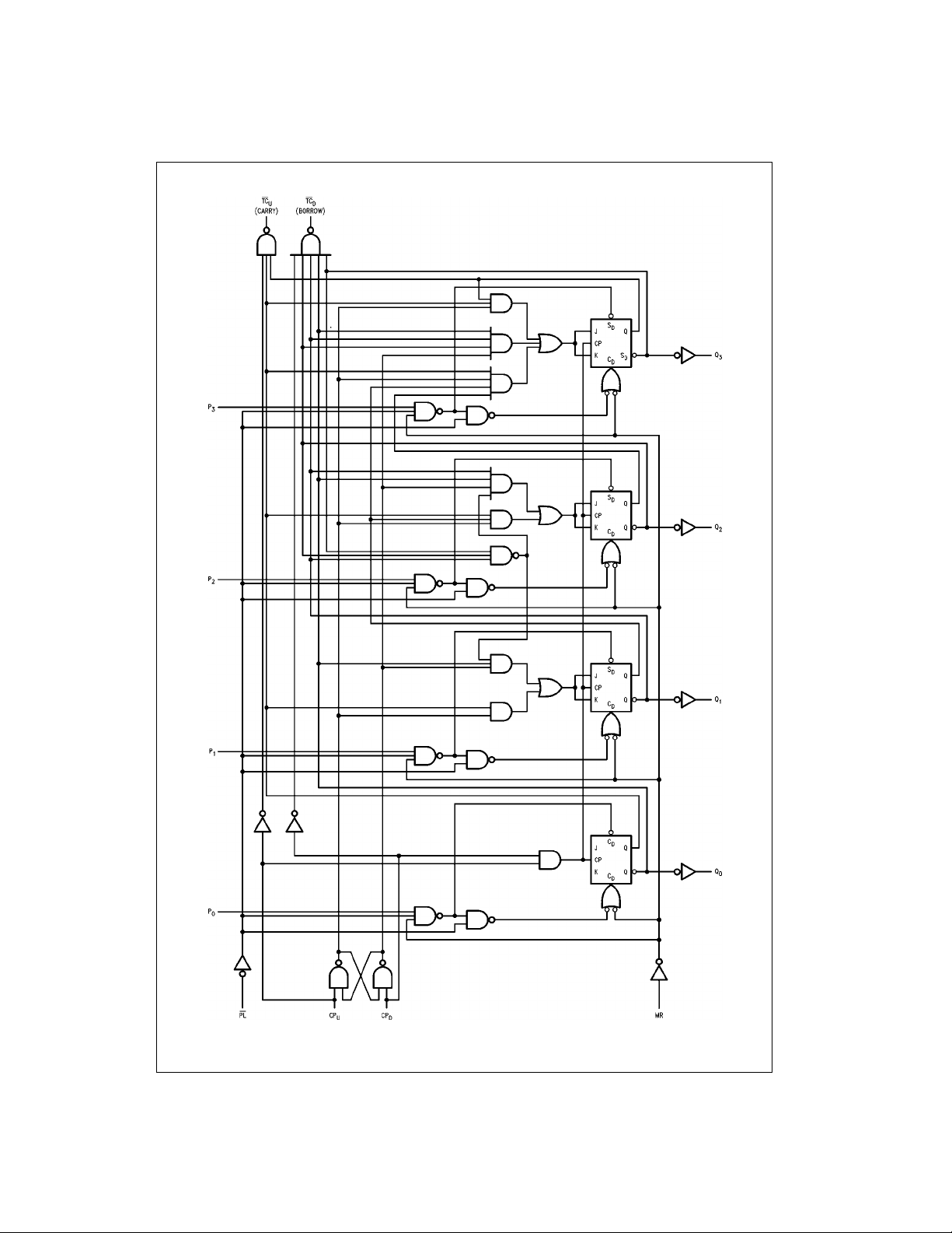
Logic Diagram
74F192
Please note that this d iagram is provided only f or t he understanding of lo gic operations and should not be used to estim ate propagation delays.
3 www.fairchildsemi.com
Page 4
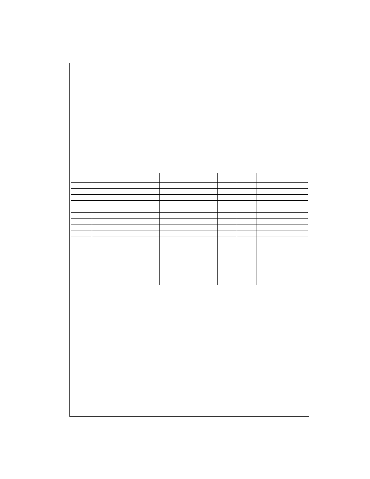
Absolute Maximum Ratings(Note 1) Recommended Operating
Storage Temperature −65°C to +150°C
74F192
Ambient Temperature under Bias −55°C to +125°C
Junction Temperature under Bias −55°C to +150°C
Pin Potential to Ground Pin −0.5V to +7.0V
V
CC
Input Voltage (Note 2) −0.5V to +7.0V
Input Current (Note 2) −30 mA to +5.0 mA
Voltage Applied to Output
in HIGH State (with V
CC
= 0V)
Standard Output −0.5V to V
3-STATE Output −0.5V to +5.5V
Current Applied to Output
in LOW State (Max) twice the rated I
OL
Conditions
Free Air Ambient Temperature 0°C to +70°C
Supply Voltage +4.5V to +5.5V
Note 1: Absolute maximum ratings are values beyond which the device
may be damaged or have its useful life impaired. Functional operation
CC
under these conditi ons is not implied.
Note 2: Either voltage limit or curren t limit is sufficient to protec t in put s .
(mA)
DC Electrical Characteristics
Symbol Parameter Min Typ Max Units
V
IH
V
IL
V
CD
V
OH
V
OL
I
IH
I
BVI
I
CEX
V
ID
I
OD
I
IL
I
OS
I
CCL
Input HIGH Voltage 2.0 V Recognized as a HIGH Signal
Input LOW Voltage 0.8 V Recognized as a LOW Signal
Input Clamp Diode Voltage −1.2 V Min IIN = −18 mA
Output HIGH Voltage 10% V
5% V
Output LOW Voltage 10% V
Input HIGH Current 5.0 µAMaxVIN = 2.7V
Input HIGH Current Breakdown Test 7.0 µAMaxVIN = 7.0V
Output HIGH Leakage Current 50 µAMaxV
Input Leakage 4.7 5 V 0.0 IID = 1.9 µA
Test All Other Pins Grounded
Output Leakage 3.75 µA0.0V
Circuit Current All Other Pins Grounded
Input LOW Current −0.6 mA Max VIN = 0.5V, Except CPu, CP
Output Short-Circuit Current −60 −150 mA Max V
Power Supply Current 38 55 mA Max VO = LOW
2.5
CC
2.7 IOH = −1 mA
CC
CC
0.5 V Min IOL = 20 mA
−1.8 VIN = 0.5V, CPu, CP
V
CC
VMin
IOH = −1 mA
= V
OUT
= 150 mV
IOD
= 0V
OUT
Conditions
CC
D
D
www.fairchildsemi.com 4
Page 5
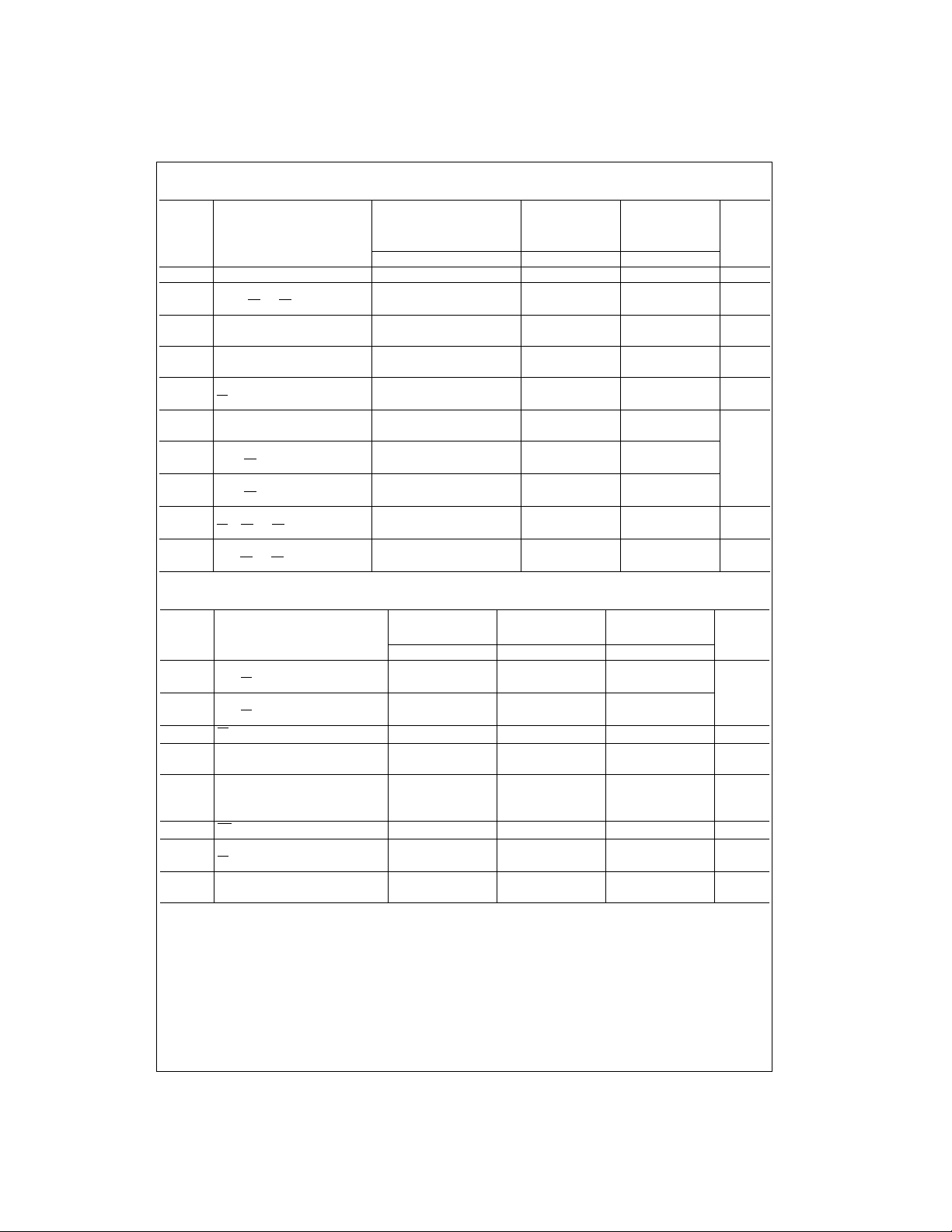
AC Electrical Characteristics
Symbol Parameter
f
t
t
t
t
t
t
t
t
t
t
t
t
t
t
t
MAX
PLH
PHL
PLH
PHL
PLH
PHL
PLH
PHL
PHL
PLH
PHL
PLH
PHL
PLH
PHL
Maximum Clock Frequency 100 125 75 90 MHz
Propagation Delay CPU or 4.0 7.0 9.0 4.0 10.5 4.0 10.0
CPD to TCU or TC
Propagation Delay 4.0 6.5 8.5 4.0 10.0 4.0 9.5
CPU or CPD to Q
n
Propagation Delay 3.0 4.5 7.0 3.0 8.5 3.0 8.0
Pn to Q
n
Propagation Delay 5.0 8.5 11.0 5.0 13.5 5.0 12.0
PL to Q
n
Propagation Delay 6.5 11.0 14.5 6.5 16.0 6.5 15.5 ns
MR to Q
n
Propagation Delay 6.0 10.5 13.5 6.0 15.0 6.0 14.5
MR to TC
U
Propagation Delay 7.0 11.5 14.5 7.0 16.0 7.0 15.5
MR to TC
D
Propagation Delay 7.0 12.0 15.5 7.0 18.5 7.0 16.5
PL to TCU or TC
D
Propagation Delay 7.0 11.5 14.5 7.0 16.5 7.0 15.5
Pn to TCU or TC
D
TA = +25°CT
VCC = +5.0V CL = 50 pF CL = 50 pF
CL = 50 pF
Min Typ Max Min Max Min Max
D
3.5 6.0 8.0 3.5 9.5 3.5 9.0
5.5 9.5 12.5 5.5 14.0 5.5 13.5
6.0 11.0 14.5 6.0 16.5 6.0 15.5
5.5 10.0 13.0 5.5 15.0 5.5 14.0
7.0 11.5 14.5 7.0 17.5 7.0 15.5
6.5 11.0 14.0 6.5 16.5 6.5 15.0
= −55°C to +125°CTA = 0°C to +70°C
A
Units
AC Operating Requirements
TA = +25°CT
Symbol Parameter
Min Max Min Max Min Max
tS(H) Setup Time, HIGH or LOW 4.5 6.0 5.0 ns
tS(L)
Pn to PL
4.5 6.0 5.0
tH(H) Hold Time, HIGH or LOW 2.0 2.0 2.0
tH(L)
tW(L)
Pn to PL
PL Pulse Width, LOW
tW(L) CPU or CP
D
2.0 2.0 2.0
6.0 7.5 6.0 ns
5.0 7.0 5.0 ns
Pulse Width, LOW
tW(L) CPU or CP
D
Pulse Width, LOW 10.0 12.0 10.0 ns
(Change of Direction)
tW(H)
t
REC
t
REC
MR Pulse Width, HIGH
Recovery Time 6.0 8.0 6.0 ns
PL to CPU or CP
D
Recovery Time 4.0 4.5 4.0 ns
MR to CPU or CP
D
6.0 6.0 6.0 ns
= −55°C to +125°CTA = 0°C to +70°C
A
UnitsVCC = +5.0V
74F192
ns
ns
ns
ns
ns
ns
5 www.fairchildsemi.com
Page 6
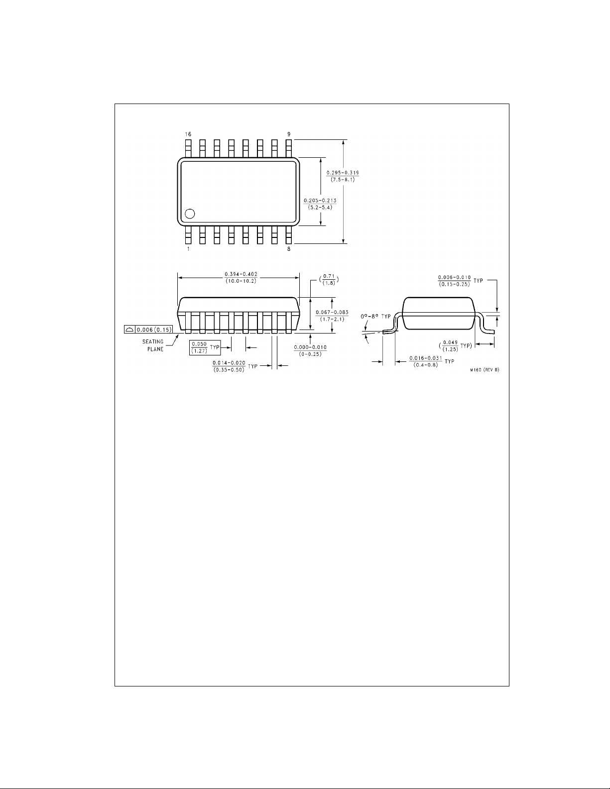
Physical Dimensions inches (millimeters) unless otherwise noted
74F192
16-Lead Small Outline Package ( SOP), EIAJ TYPE II, 5.3mm Wide
Package Number M16D
www.fairchildsemi.com 6
Page 7
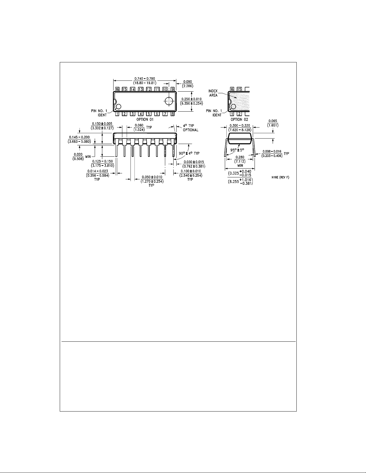
Physical Dimensions inches (millimeters) unless otherwise noted (Continued)
74F192 Up/Down Decade Counter with Separate Up/Down Clocks
16-Lead Plastic Dual-In-Line Package (PDIP), JEDEC MS-001, 0.300 Wide
LIFE SUPPORT POLICY
FAIRCHILD’S PRODUCTS ARE NOT AUTHORIZED FOR USE AS CRITICAL COMPONENTS IN LIFE SUPPORT
DEVICES OR SYSTEMS WITHOUT THE EXPRESS WRITTEN APPROVAL OF THE PRESIDENT OF FAIRCHILD
SEMICONDUCTOR CORPORATION. As used herein:
1. Life support devices or systems are devices or systems
which, (a) are intended for surgical implant into the
body, or (b) support or sustain life, and (c) whose failure
to perform when properly used in accordance with
instructions for use provide d in the labe l ing, can be re asonably expected to result in a significant injury to the
user.
Package Number N16E
2. A critical componen t in any com ponen t of a life s upport
device or system whose failu re to perform can b e reasonably expected to cause the failure of the l ife s upp or t
device or system, or to affect its safety or effectiveness.
www.fairchildsemi.com
Fairchild does not assume any responsibility for use of any circuitry described, no circuit patent licenses are implied and Fairchild reserves the right at any time without notice to change said circuitry and specifications.
 Loading...