

Page 1
SN74ALS234
64 × 4 ASYNCHRONOUS FIRST-IN, FIRST-OUT MEMORY
SDAS106B – OCTOBER 1986 – REVISED SEPTEMBER 1993
D
Asynchronous Operation
D
Organized as 64 Words by 4 Bits
D
Data Rates From 0 to 30 MHz
D
3-State Outputs
D
Package Options Include Plastic
Small-Outline Packages (DW), Plastic
J-Leaded Chip Carriers (FN), and Standard
Plastic 300-mil DIPs (N)
description
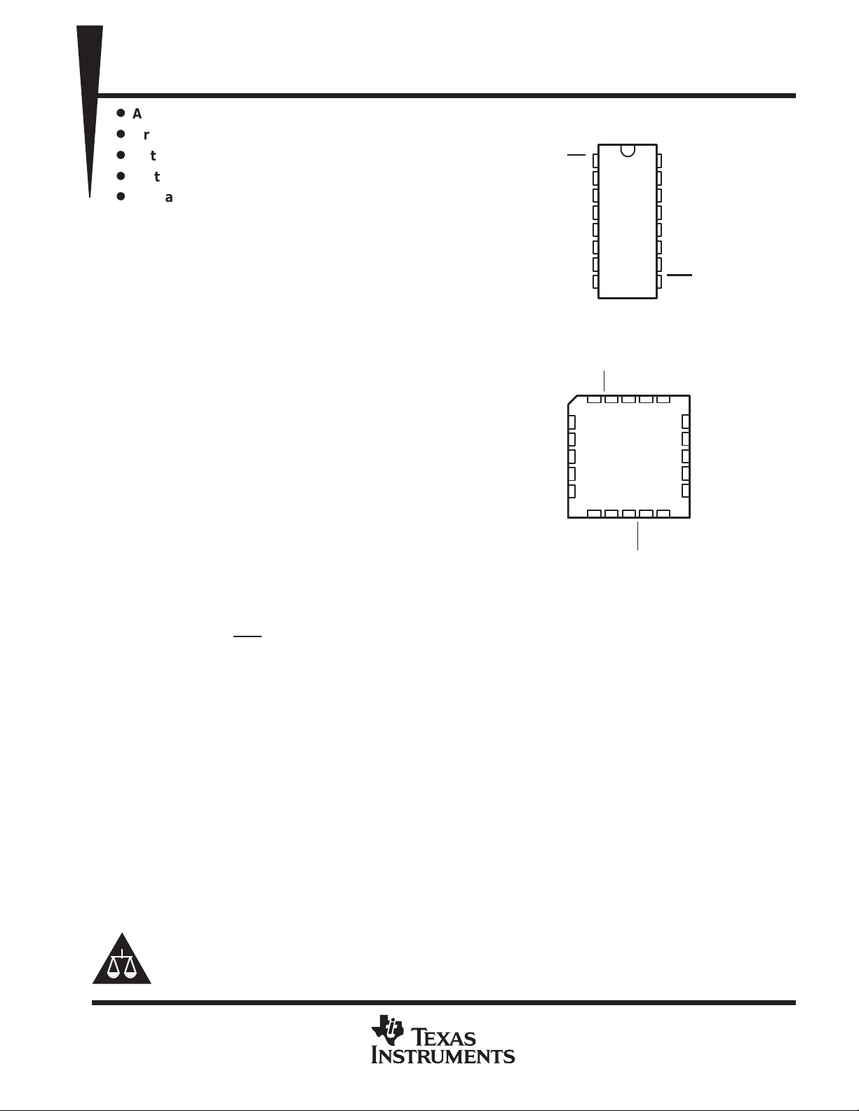
DW OR N PACKAGE
(TOP VIEW)
1
OE
IR
SI
D0
D1
D2
D3
GND
16
2
15
3
14
4
13
5
12
6
11
7
10
8
V
CC
SO
OR
Q0
Q1
Q2
Q3
RST
9
The SN74ALS234 is a 256-bit memory utilizing
advanced low-power Schottky IMPACT
technology. It features high speed with fast
fall-through times and is organized as 64 words by
4 bits.
FN PACKAGE
(TOP VIEW)
OE
NC
IR
V
CC
SO
A first-in, first-out (FIFO) memory is a storage
device that allows data to be written into and read
from its array at independent data rates. The
SN74ALS234 is designed to process data at rates
from 0 to 30 MHz in a bit-parallel format, word by
word.
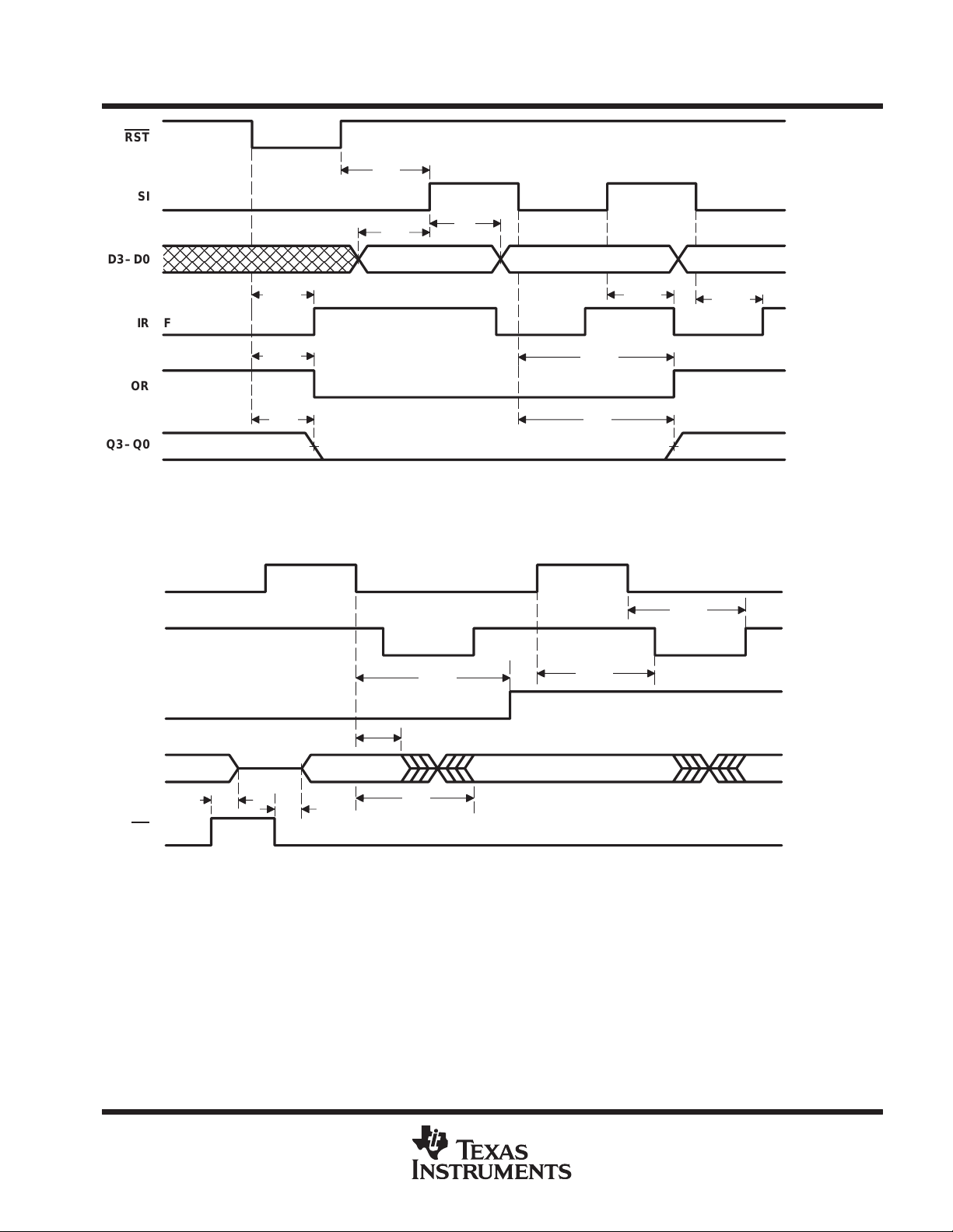
Data is written into memory on the rising edge of
the shift-in (SI) input. When SI goes low, the first
data word ripples through to the output (see
Figure 1). As the FIFO fills up, the data words
stack up in the order they were written. When the
D0
NC
D1
D2
NC – No internal connection
SI
3 2 1 20 19
4
5
6
7
8
910111213
D3
NC
GND
RST
18
17
16
15
14
Q3
OR
Q0
NC
Q1
Q2
FIFO is full, additional shift-in pulses have no
effect. Data is shifted out of memory on the falling edge of the shift-out (SO) input (see Figure 2). When the FIFO
is empty , additional SO pulses have no effect. The last data word remains at the outputs until a new word falls
through or reset (RST
) goes low.
Status of the SN74ALS234 FIFO memory is monitored by the output-ready (OR) and input-ready (IR) flags.
When OR is high, valid data is available at the outputs. OR is low when SO is high and stays low when the FIFO
is empty . IR is high when the inputs are ready to receive more data. IR is low when SI is high and stays low when
the FIFO is full.
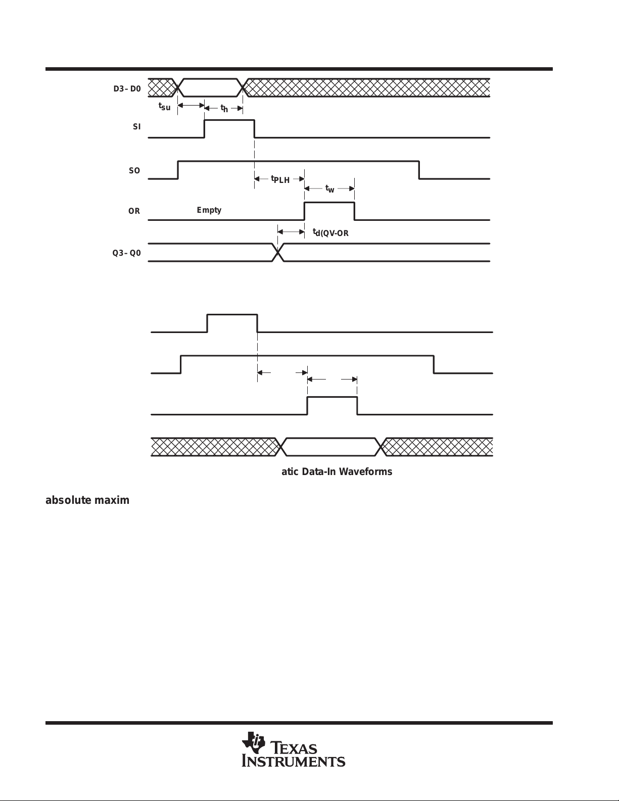
When the FIFO is empty, input data is shifted to the output automatically when SI goes low. If SO is held high
during this time, the OR flag pulses high indicating valid data at the outputs (see Figure 3).
When the FIFO is full, data can be shifted in automatically by holding SI high and taking SO low. One propagation
delay after SO goes low, IR will go high. If SI is still high when IR goes high, data at the inputs are automatically
shifted in. Since IR is normally low when the FIFO is full and SI is high, only a high-level pulse is seen on the
IR output (see Figure 4).
Please be aware that an important notice concerning availability, standard warranty, and use in critical applications of
Texas Instruments semiconductor products and disclaimers thereto appears at the end of this data sheet.
IMPACT is a trademark of Texas Instruments Incorporated.
PRODUCTION DATA information is current as of publication date.
Products conform to specifications per the terms of Texas Instruments
standard warranty. Production processing does not necessarily include
testing of all parameters.
POST OFFICE BOX 655303 • DALLAS, TEXAS 75265
Copyright 1993, Texas Instruments Incorporated
1
Page 2
SN74ALS234
64 × 4 ASYNCHRONOUS FIRST-IN, FIRST-OUT MEMORY
SDAS106B – OCTOBER 1986 – REVISED SEPTEMBER 1993
description (continued)
The FIFO must be reset after power up with a low-level pulse on the master reset (RST) input. This sets IR high
and OR low signifying that the FIFO is empty. Resetting the FIFO sets the outputs to a low logic level (see
Figure 1). If SI is high when RST
SI goes low. If SI goes low before RST
outputs are noninverting with respect to the data inputs and are at high impedance when the output-enable (OE
input is high. OE
does not affect the IR or OR.
The SN74ALS234 is characterized for operation from 0°C to 70°C.
goes high, the input data is shifted in and IR goes low and remains low until
goes high, the input data will not be shifted in and IR goes high. Data
)
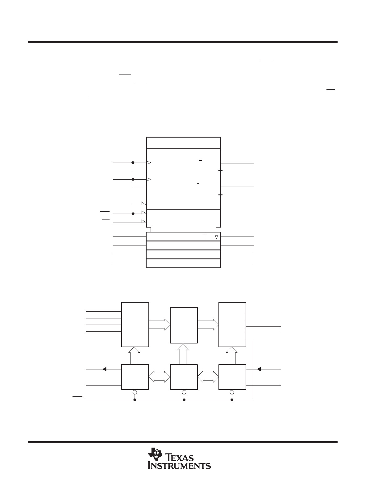
logic symbol
†
This symbol is in accordance with ANSI/IEEE Standard 91-1984 and IEC Publication 617-12.
†
FIFO 64 × 4
3
SI
15
SO
9
RST
1
OE
4
D0 Q0
5
D1
6
D2
7
D3
5 + /C1
G2
4–
G3
CT = 0
R
EN6
1D
CTR
(CT > 0) G4
(CT < 64) G5
CT > 0
3
2CT < 64
6
functional block diagram
14
13
12
11
10
OR
2
IR
Q1
Q2
Q3
4
D0
5
D1
6
D2
7
D3
2
IR
3
SI
RST
Pin numbers shown are for the DW and N packages.
2
9
FIFO
Input
Stage
Input-
Control
Logic
POST OFFICE BOX 655303 • DALLAS, TEXAS 75265
62 × 4 Bit
Register
Register-
Control
Logic
FIFO
Output
Stage
OutputControl
Logic
13
12
11
10
15
14
Q0
Q1
Q2
Q3
SO
OR
Page 3
POST OFFICE BOX 655303 • DALLAS, TEXAS 75265
p
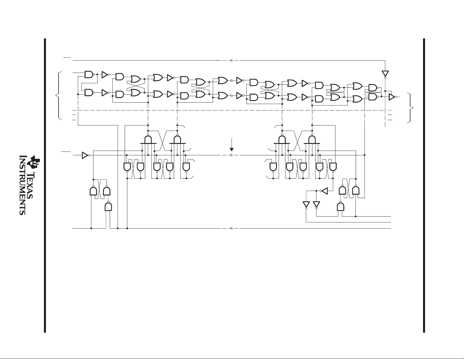
logic diagram (positive logic)
OE
D0
Data Inputs
D1
D2
D3
Word 64 Word 63 Word 3 Word 2
Words 4 – 6
Same as 3 or 63
Word 1
Q0
uts
Q1
Q2
Q3
Data Out
RST
SI
SO
OR
IR
64 × 4 ASYNCHRONOUS FIRST-IN, FIRST-OUT MEMORY
SDAS106B – OCTOBER 1986 – REVISED SEPTEMBER 1993
SN74ALS234
3
Page 4
SN74ALS234
64 × 4 ASYNCHRONOUS FIRST-IN, FIRST-OUT MEMORY
SDAS106B – OCTOBER 1986 – REVISED SEPTEMBER 1993
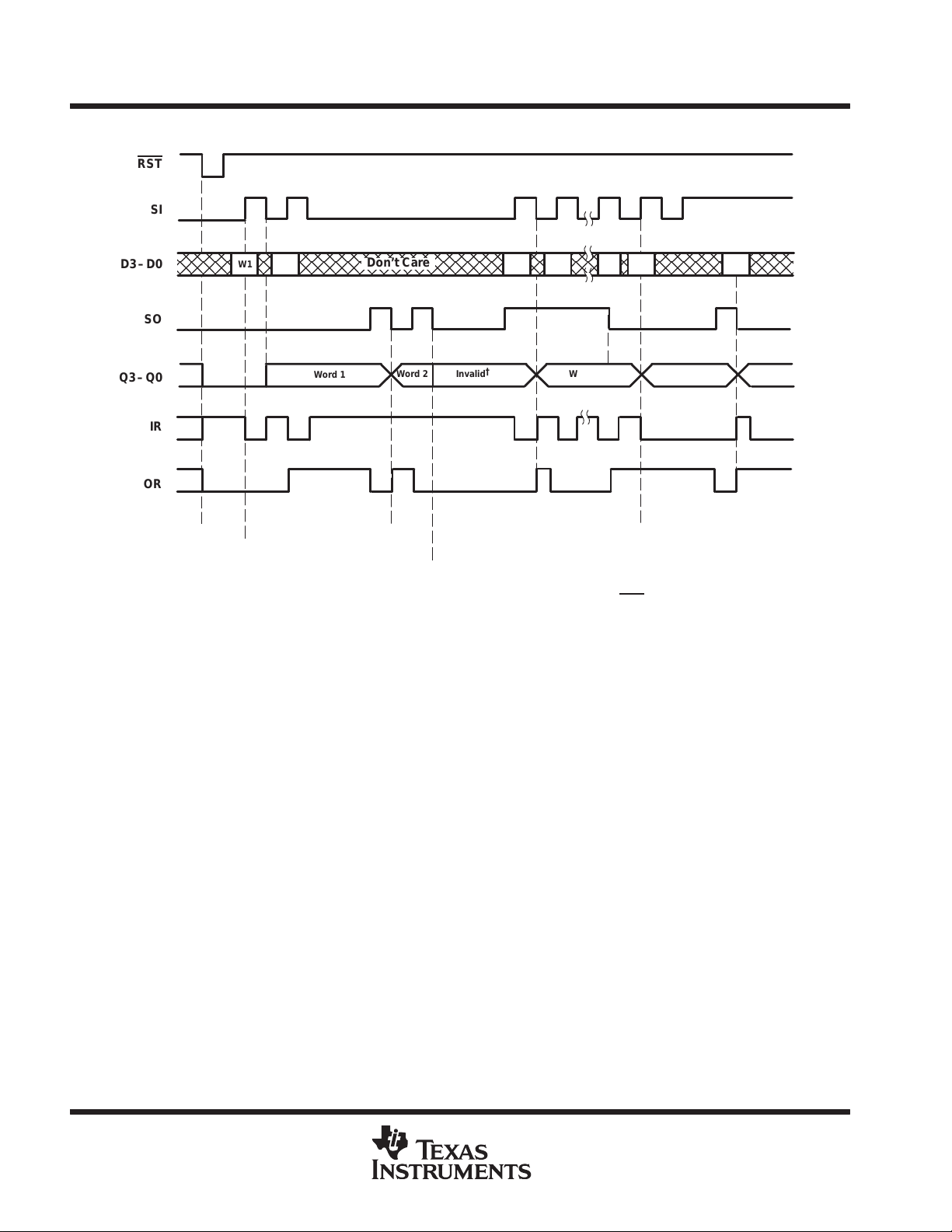
timing diagram
RST
SI
W1
D3–D0
SO
Q3–Q0
IR
OR
Clear
Shift In
†
The last data word shifted out of the FIFO remains at the output until a new word falls through or a RST
‡
While the output data is considered valid only when the OR flag is high, the stored data remains at the outputs. Any additional words written into
the FIFO will stack up behind the first word and will not appear at the output until SO is taken low.
W2 W1 W2 W63 W64 W1
Word 1
W1
Don’t Care
Word 2 Invalid
Shift Out
W2
Empty
†
Word 1
‡
Full
pulse clears the FIFO.
Word 2 Word 3
4
POST OFFICE BOX 655303 • DALLAS, TEXAS 75265
Page 5
RST
D3–D0
SN74ALS234
64 × 4 ASYNCHRONOUS FIRST-IN, FIRST-OUT MEMORY
SDAS106B – OCTOBER 1986 – REVISED SEPTEMBER 1993
t
su
SI
t
t
su
h
Full
IR
OR
Q3–Q0
NOTE: SO is low.
SO
OR
IR
Full
t
PLH
t
PHL
t
Empty
pd
Figure 1. Master Reset and Data-In Waveforms
t
PLH
t
d(SOL-QX)
t
t
PHL
PLH
t
pd
t
PHL
t
PLH
t
PLH
Q3–Q0
t
dis
OE
NOTE: SI is low.
t
t
en
pd
Figure 2. Data-Out Waveforms
POST OFFICE BOX 655303 • DALLAS, TEXAS 75265
5
Page 6
SN74ALS234
64 × 4 ASYNCHRONOUS FIRST-IN, FIRST-OUT MEMORY
SDAS106B – OCTOBER 1986 – REVISED SEPTEMBER 1993
D3–D0
t
su
SI
t
h
SO
OR
Q3–Q0
SO
D3–D0
t
PLH
Empty
Invalid
t
w
t
d(QV-ORH)
Figure 3. Data Fall-Through Waveforms
SI
IR
Full Full
t
PLH
t
w
Figure 4. Automatic Data-In Waveforms
absolute maximum ratings over operating free-air temperature range (unless otherwise noted)
Supply voltage, V
Input voltage, V
Voltage applied to a disabled 3-state output 5.5 V. . . . . . . . . . . . . . . . . . . . . . . . . . . . . . . . . . . . . . . . . . . . . . . . . .
Operating free-air temperature range, T
Storage temperature range –65°C to 150°C. . . . . . . . . . . . . . . . . . . . . . . . . . . . . . . . . . . . . . . . . . . . . . . . . . . . . . .
†
Stresses beyond those listed under “absolute maximum ratings” may cause permanent damage to the device. These are stress ratings only, and
functional operation of the device at these or any other conditions beyond those indicated under “recommended operating conditions” is not
implied. Exposure to absolute-maximum-rated conditions for extended periods may affect device reliability.
NOTE 1: All voltage values are with respect to GND.
(see Note 1) 7 V. . . . . . . . . . . . . . . . . . . . . . . . . . . . . . . . . . . . . . . . . . . . . . . . . . . . . . . . . . . .
CC
7 V. . . . . . . . . . . . . . . . . . . . . . . . . . . . . . . . . . . . . . . . . . . . . . . . . . . . . . . . . . . . . . . . . . . . . . . . . . .
I
A
0°C to 70°. . . . . . . . . . . . . . . . . . . . . . . . . . . . . . . . . . . . . . . . . . . . . . . . .
†
6
POST OFFICE BOX 655303 • DALLAS, TEXAS 75265
Page 7
IOHHigh-level output current
mA
IOLLow-level output current
mA
twPulse duration
ns
t
Set
SI↑
ns
Any Q
V
V
Any Q
V
V
V
V
IR, OR
V
V
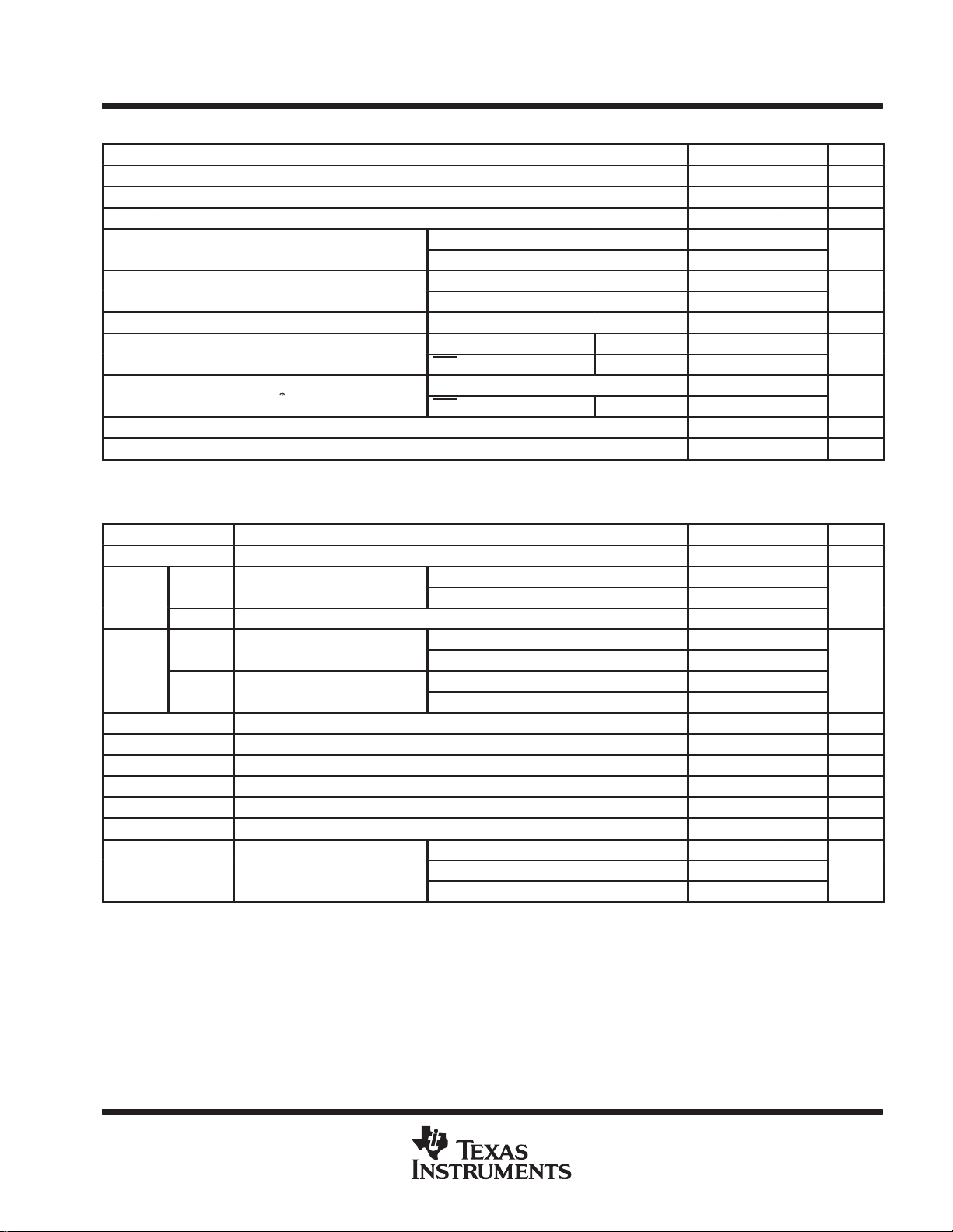
recommended operating conditions
V
CC
V
IH
V
IL
f
clock
su
t
h
T
A
Supply voltage 4.5 5 5.5 V
High-level input voltage 2 V
Low-level input voltage 0.8 V
p
p
Clock frequency SI or SO 0 30 MHz
up time before
Hold time, data after SI↑ 17 ns
Operating free-air temperature 0 70 °C
SN74ALS234
64 × 4 ASYNCHRONOUS FIRST-IN, FIRST-OUT MEMORY
SDAS106B – OCTOBER 1986 – REVISED SEPTEMBER 1993
MIN NOM MAX UNIT
Q outputs – 2.6
IR and OR – 0.4
Q outputs 24
IR and OR 8
SI or SO High or low 15
RST Low 15
Data 0
RST High (inactive) 15
electrical characteristics over recommended operating free-air temperature range (unless
otherwise noted)
PARAMETER TEST CONDITIONS MIN TYP†MAX UNIT
V
IK
V
OH
IR, OR VCC = 4.5 V, IOH = –0.4 mA 2.7 3.4
OL
I
OZH
I
OZL
I
I
I
IH
I
IL
‡
I
O
I
CC
†
All typical values are at VCC = 5 V, TA = 25°C.
‡
The output conditions have been chosen to produce a current that closely approximates one half of the true short-circuit output current, IOS.
VCC = 4.5 V, II = –18 mA –1.2 V
= 4.5
CC
= 4.5
CC
= 4.5
CC
VCC = 5.5 V, VO = 2.7 V 20 µA
VCC = 5.5 V, VO = 0.4 V –20 µA
VCC = 5.5 V, VI = 7 V 0.1 mA
VCC = 5.5 V, VI = 2.7 V 20 µA
VCC = 5.5 V, VI = 0.4 V –0.1 mA
VCC = 5.5 V, VO = 2.25 V –30 –112 mA
VCC = 5.5 V High 97 142
IOH = –1 mA
IOH = –2.6 mA 2.4 3.2
IOL = 12 mA 0.25 0.4
IOL = 24 mA 0.35 0.5
IOL = 4 mA 0.25 0.4
IOL = 8 mA 0.35 0.5
Low 100 145
Disabled 103 148
V
mA
POST OFFICE BOX 655303 • DALLAS, TEXAS 75265
7
Page 8
SN74ALS234
f
MH
IR
ns
OR
ns
RST↓
ns
64 × 4 ASYNCHRONOUS FIRST-IN, FIRST-OUT MEMORY
SDAS106B – OCTOBER 1986 – REVISED SEPTEMBER 1993
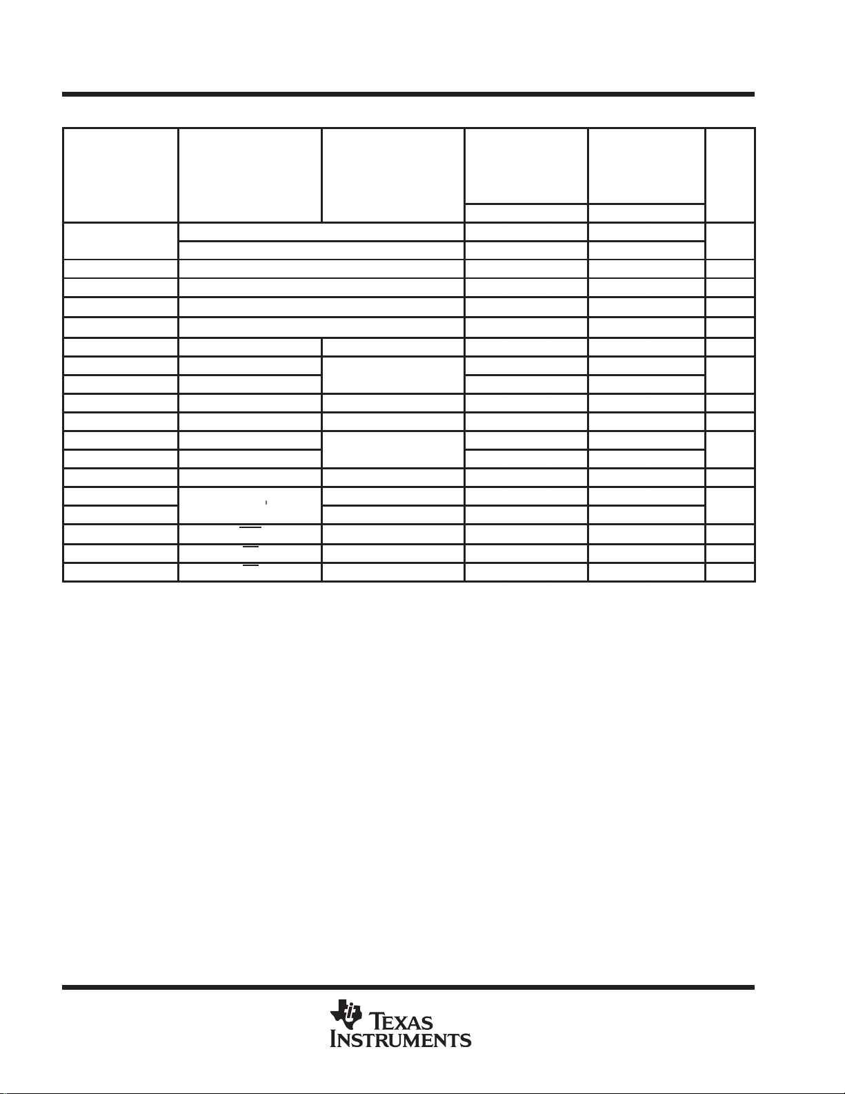
switching characteristics (see Figure 5)
VCC = 5 V,
CL = 50 pF,
PARAMETER
max
‡
tw
§
tw
t
d(QV-ORH)
t
d(SOL-QX)
t
pd
t
PHL
t
PLH
¶
t
PLH
t
pd
t
PHL
t
PLH
¶
t
PLH
t
PHL
t
PLH
t
PHL
t
dis
t
en
†
For conditions shown as MIN or MAX, use the appropriate value specified under recommended operating conditions.
‡
The IR output pulse occurs when the FIFO is full, SI is high, and SO is pulsed (see Figure 4).
§
The OR output pulse occurs when the FIFO is empty, SO is high, and SI is pulsed (see Figure 3).
¶
Data throughput or fall-through times
FROM
(INPUT)
SI 35 30
SO 35 30
IR high 15 8 ns
OR high 19 8 ns
Q valid before OR↑ 6 9 –5 12 ns
Q valid after SO↓ 13 4 ns
SI↓ Q 600 800 350 1000 ns
SI↑
SI↓
SI↓ OR 600 800 350 1000 ns
SO↓ Q 13 17 4 22 ns
SO↑
SO↓
SO↓ IR 600 800 350 1000 ns
RST↓
OE↑ Q 7 13 2 15 ns
OE↓ Q 6 12 2 13 ns
TO
(OUTPUT)
OR 22 26 10 34
IR 17 21 6 27
Q 14 17 5 19 ns
R1 = 500 Ω,
R2 = 500 Ω,
TA = 25°C
MIN TYP MAX MIN MAX
20 26 8 30
16 21 6 25
23 27 7 33
20 24 6 30
VCC = 4.5 V to 5.5 V,
CL = 50 pF,
R1 = 500 Ω,
R2 = 500 Ω,
TA = MIN to MAX
UNIT
†
z
8
POST OFFICE BOX 655303 • DALLAS, TEXAS 75265
Page 9
SN74ALS234
64 × 4 ASYNCHRONOUS FIRST-IN, FIRST-OUT MEMORY
SDAS106B – OCTOBER 1986 – REVISED SEPTEMBER 1993
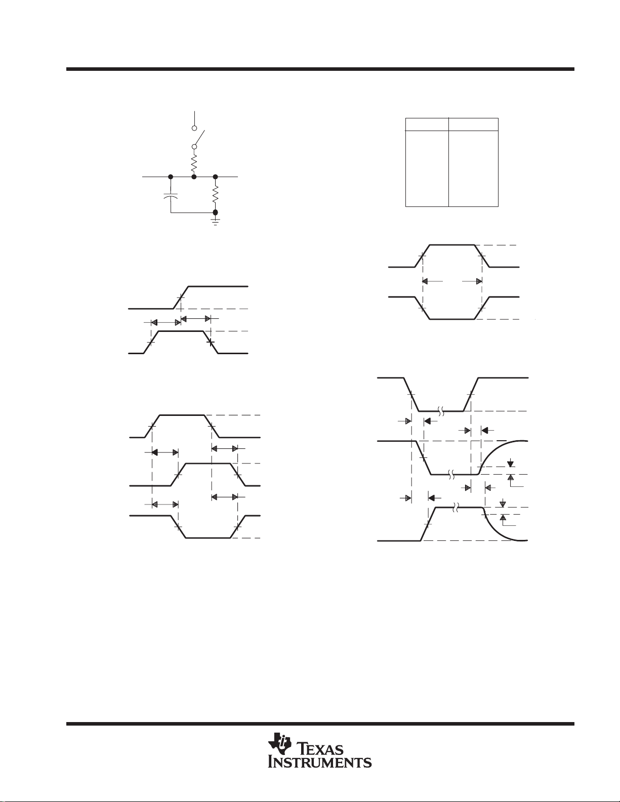
PARAMETER MEASUREMENT INFORMATION
From Output
Under Test
CL = 50 pF
(see Note A)
LOAD CIRCUIT FOR 3-STATE OUTPUTS
Timing
Input
Data
Input
Input
(see Note B)
In-Phase
Output
Out-of-Phase
Output
7 V
S1
t
su
1.3 V
VOLTAGE WAVEFORMS
SETUP AND HOLD TIMES
1.3 V
t
PLH
t
PHL
VOLTAGE WAVEFORMS
PROPAGATION DELAY TIMES
Open
R1 = 500 Ω
1.3 V
1.3 V 1.3 V
Test Point
R2 = 500 Ω
t
h
1.3 V
1.3 V
1.3 V1.3 V
3.5 V
0.3 V
3.5 V
0.3 V
t
PHL
t
PLH
3.5 V
0.3 V
V
OH
V
OL
V
OH
V
OL
High-Level
Pulse
Low-Level
Pulse
Output
Control
Waveform 1
S1 Closed
(see Note C)
Waveform 2
S1 Open
(see Note C)
ENABLE AND DISABLE TIMES, 3-STATE OUTPUTS
SWITCH POSITION TABLE
TEST S1
t
PLH
t
PHL
t
PZH
t
PZL
t
PHZ
t
PLZ
1.3 V
1.3 V
VOLTAGE WAVEFORMS
PULSE DURATION
1.3 V
t
PZL
1.3 V
t
t
PZH
VOLTAGE WAVEFORMS
PHZ
1.3 V
t
w
Open
Open
Open
Closed
Open
Closed
1.3 V
1.3 V
1.3 V
t
PLZ
V
0.3 V
3.5 V
0.3 V
3.5 V
0.3 V
3.5 V
0.3 V
3.5 V
OL
0.3 V
V
OH
0 V
NOTES: A. CL includes probe and jig capacitance.
B. All input pulses are supplied by generators having the following characteristics: PRR ≤ 1 MHz, Zo = 50 Ω, tr ≤ 2 ns, tf≤ 2 ns.
C. W aveform 1 is for an output with internal conditions such that the output is low except when disabled by the output control.
Waveform 2 is for an output with internal conditions such that the output is high except when disabled by the output control.
D. The outputs are measured one at a time with one transition per measurement.
Figure 5. Load Circuit and Voltage Waveforms
POST OFFICE BOX 655303 • DALLAS, TEXAS 75265
9
Page 10
SN74ALS234
64 × 4 ASYNCHRONOUS FIRST-IN, FIRST-OUT MEMORY
SDAS106B – OCTOBER 1986 – REVISED SEPTEMBER 1993
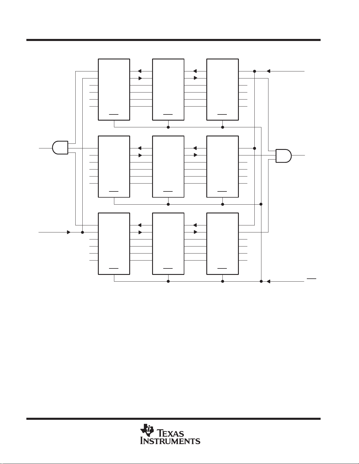
APPLICATION INFORMATION
IR
SI
D0
D1
D2
D3
IR
SI
IR
SI
D0
D1
D2
D3
IR
SI
D0
D1
D2
D3
SO
OR
Q0
Q1
Q2
Q3
RST
SO
OR
Q0
Q1
Q2
Q3
RST
SO
OR
Q0
Q1
Q2
Q3
IR
SI
D0
D1
D2
D3
IR
SI
D0
D1
D2
D3
IR
SI
D0
D1
D2
D3
RST
RST
SO
OR
Q0
Q1
Q2
Q3
SO
OR
Q0
Q1
Q2
Q3
SO
OR
Q0
Q1
Q2
Q3
IR
SI
D0
D1
D2
D3
IR
SI
D0
D1
D2
D3
IR
SI
D0
D1
D2
D3
SO
OR
Q0
Q1
Q2
Q3
RST
SO
OR
Q0
Q1
Q2
Q3
RST
SO
OR
Q0
Q1
Q2
Q3
SO
OR
RST
RST
Figure 6. 192-Word by 12-Bit Expansion
RST
RST
10
POST OFFICE BOX 655303 • DALLAS, TEXAS 75265
Page 11

IMPORTANT NOTICE
T exas Instruments and its subsidiaries (TI) reserve the right to make changes to their products or to discontinue
any product or service without notice, and advise customers to obtain the latest version of relevant information
to verify, before placing orders, that information being relied on is current and complete. All products are sold
subject to the terms and conditions of sale supplied at the time of order acknowledgement, including those
pertaining to warranty, patent infringement, and limitation of liability.
TI warrants performance of its semiconductor products to the specifications applicable at the time of sale in
accordance with TI’s standard warranty. T esting and other quality control techniques are utilized to the extent
TI deems necessary to support this warranty . Specific testing of all parameters of each device is not necessarily
performed, except those mandated by government requirements.
CERT AIN APPLICATIONS USING SEMICONDUCTOR PRODUCTS MA Y INVOLVE POTENTIAL RISKS OF
DEATH, PERSONAL INJURY, OR SEVERE PROPERTY OR ENVIRONMENTAL DAMAGE (“CRITICAL
APPLICATIONS”). TI SEMICONDUCTOR PRODUCTS ARE NOT DESIGNED, AUTHORIZED, OR
WARRANTED TO BE SUITABLE FOR USE IN LIFE-SUPPORT DEVICES OR SYSTEMS OR OTHER
CRITICAL APPLICA TIONS. INCLUSION OF TI PRODUCTS IN SUCH APPLICATIONS IS UNDERST OOD TO
BE FULLY AT THE CUSTOMER’S RISK.
In order to minimize risks associated with the customer’s applications, adequate design and operating
safeguards must be provided by the customer to minimize inherent or procedural hazards.
TI assumes no liability for applications assistance or customer product design. TI does not warrant or represent
that any license, either express or implied, is granted under any patent right, copyright, mask work right, or other
intellectual property right of TI covering or relating to any combination, machine, or process in which such
semiconductor products or services might be or are used. TI’s publication of information regarding any third
party’s products or services does not constitute TI’s approval, warranty or endorsement thereof.
Copyright 1999, Texas Instruments Incorporated
 Loading...