

Page 1

INTEGRATED CIRCUITS
74ABT648
Octal transceiver/register, inverting
(3-State)
Product specification
Supersedes data of 1995 Apr 17
IC23 Data Handbook
1998 Jun 08
Page 2
Philips Semiconductors Product specification
74ABT648Octal bus transceiver/register, inverting (3-State)
FEA TURES
•Combines 74ABT245 and 74ABT374 type functions in one device
•Independent registers for A and B buses
•Multiplexed real-time and stored data
•Output capability: +64mA/–32mA
•Power-up 3-state
•Power-up reset
•Live insertion/extraction permitted
•Latch-up protection exceeds 500mA per Jedec Std 17
•ESD protection exceeds 2000 V per MIL STD 883 Method 3015
and 200 V per Machine Model
DESCRIPTION
The 74ABT648 high-performance BiCMOS device combines low
static and dynamic power dissipation with high speed and high
output drive.
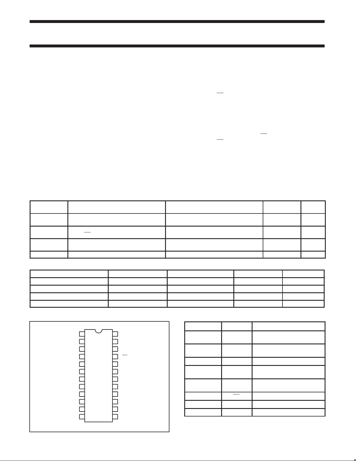
QUICK REFERENCE DATA
SYMBOL PARAMETER
t
PLH
t
PHL
C
C
I
CCZ
IN
I/O
Propagation delay
An to Bn or Bn to An
Input capacitance
CP, S, OE, DIR
I/O capacitance
Total supply current Outputs disabled; VCC =5.5V 110 µA
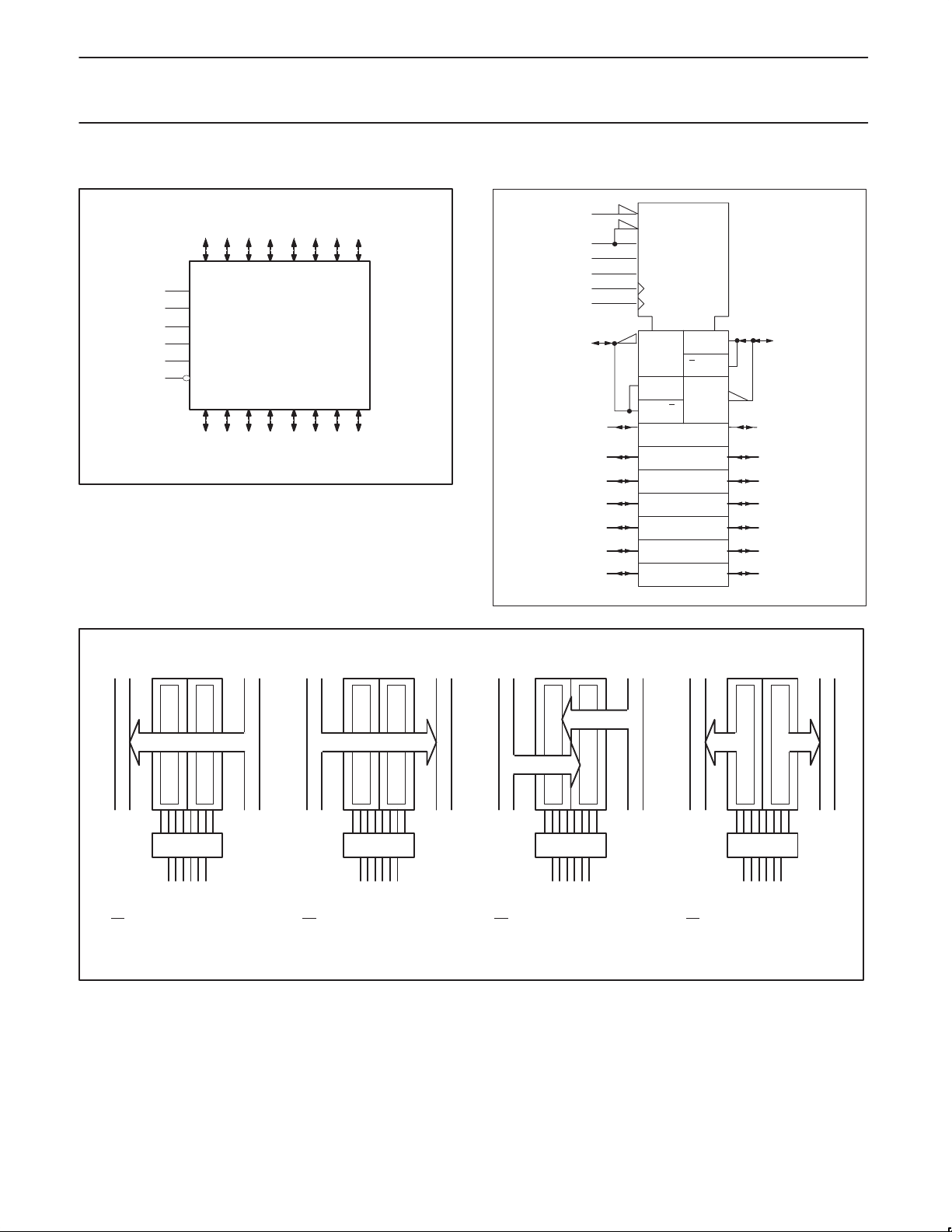
The 74ABT648 transceiver/register consists of bus transceiver
circuits with inverting 3-State outputs, D-type flip-flops, and control
circuitry arranged for multiplexed transmission of data directly from
the input bus or the internal registers. Data on the A or B bus will be
clocked into the registers as the appropriate clock pin goes High.
Output Enable (OE
) and DIR pins are provided to control the
transceiver function. In the transceiver mode, data present at the
high impedance port may be stored in either the A or B register or
both.
The Select (SAB, SBA) pins determine whether data is stored or
transferred through the device in real–time. The DIR determines
which bus will receive data when the OE
isolation mode (OE
= High), data from Bus A may be stored in the B
is active (Low). In the
register and/or data from Bus B may be stored in the A register.
Outputs from real-time, or stored registers will be inverted. When an
output function is disabled, the input function is still enabled and
may be used to store and transmit data. Only one of the two buses,
A or B may be driven at a time. The examples on the next page
demonstrate the four fundamental bus management functions that
can be performed with the 74ABT648.
CONDITIONS
T
= 25°C; GND = 0V
amb
TYPICAL UNIT
CL = 50pF; VCC = 5V 5.9 ns
VI = 0V or V
CC
Outputs disabled;
VO = 0V or V
CC
4 pF
7 pF
ORDERING INFORMATION
PACKAGES TEMPERATURE RANGE OUTSIDE NORTH AMERICA NORTH AMERICA DWG NUMBER
24-Pin Plastic DIP –40°C to +85°C 74ABT648 N 74ABT648 N SOT222-1
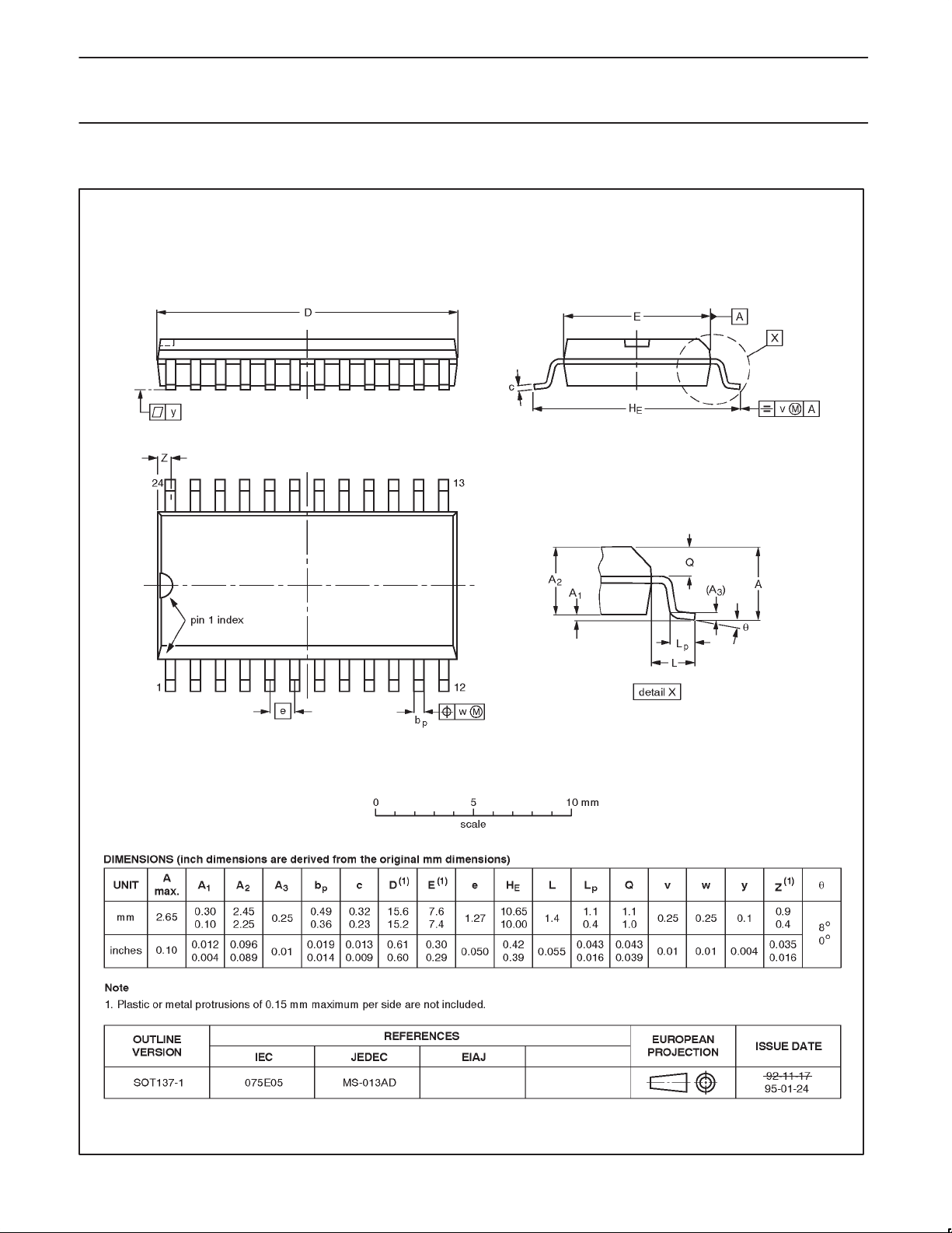
24-Pin plastic SO –40°C to +85°C 74ABT648 D 74ABT648 D SOT137-1
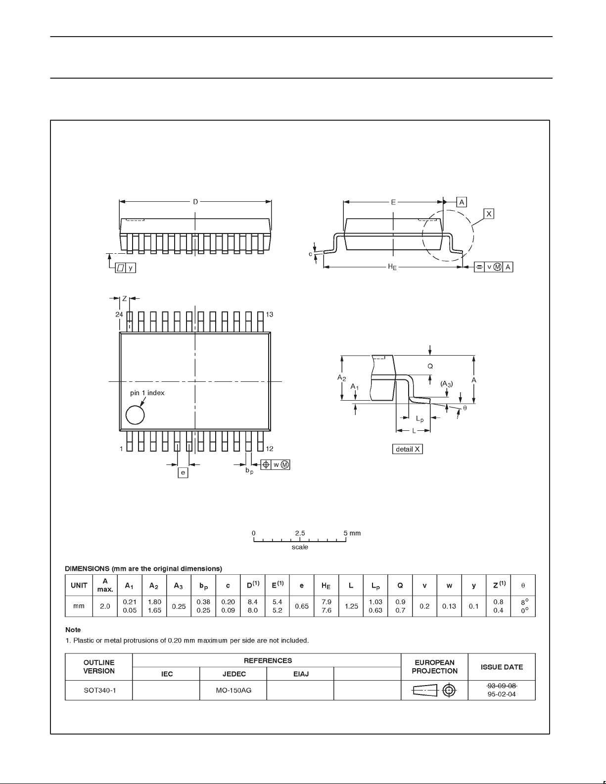
24-Pin Plastic SSOP Type II –40°C to +85°C 74ABT648 DB 74ABT648 DB SOT340-1
24-Pin Plastic TSSOP Type I –40°C to +85°C 74ABT648 PW 74ABT648PW DH SOT355-1
PIN CONFIGURATION
1
CPAB
2
SAB
3
DIR
4
A0
5
A1
6
A2
7
A3
8
A4
9
A5
10
A6
11
A7
12
GND
V
24
CPBA
23
SBA
22
OE
21
B0
20
B1
19
B2
18
B3
17
B4
16
B5
15
B6
14
B713
SA00082
CC
PIN DESCRIPTION
PIN NUMBER SYMBOL FUNCTION
1, 23
CPAB /
CPBA
2, 22 SAB / SBA
3 DIR Direction control input
4, 5, 6, 7,
8, 9, 10, 11
20, 19, 18, 17,
16, 15, 14, 13
A0 – A7 Data inputs/outputs (A side)
B0 – B7 Data inputs/outputs (B side)
21 OE Output enable input (active-Low)
12 GND Ground (0V)
24 V
CC
A to B clock input / B to A clock
input
A to B select input / B to A select
input
Positive supply voltage
1998 Jun 08 853–1613 19516
2
Page 3
Philips Semiconductors Product specification
74ABT648Octal bus transceiver/register, inverting (3-State)
LOGIC SYMBOL
3
23
22 SBA
21 OE
4567 891011
A0 A1 A2 A3 A4 A5 A6 A7
CPAB1
SAB2
DIR
CPBA
B0 B1 B2 B3 B4 B5 B6 B7
20 19 18 17 16 15 14 13
SA00083
LOGIC SYMBOL (IEEE/IEC)
21
3
22
2
23
1
4
5
6
7
8
9
10
11
G3
3EN1 [BA]
3EN2 [AB]
G6
G7
C4
C5
≥1
∇1
5D 7
17
64D
6
1
≥1
2∇
20
19
18
17
16
15
14
13
SA00156
REAL TIME BUS TRANSFER
BUS B TO BUS A
}
DIR CPABCPBA SAB SBA
OE
LLXXXL
REAL TIME BUS TRANSFER
BUS A TO BUS B
}
DIR CPABCPBA SAB SBA
OE
LHXXLX
STORAGE FROM
A, B, OR A AND B
}
DIR CPABCPBA SAB SBA
OE
LH↑ XLX
LXX↑ XX
HX↑↑XX
TRANSFER STORED DATA
TO A OR B
}
DIR CPABCPBA SAB SBA
OE
L L H H or L X H
L H H or L X H X
SA00177
1998 Jun 08
3
Page 4

Philips Semiconductors Product specification
74ABT648Octal bus transceiver/register, inverting (3-State)
FUNCTION TABLE
INPUTS DATA I/O OPERATING MODE
OE DIR CPAB CPBA SAB SBA An Bn
X X ↑ X X X Input
X
X
L
H
X
X
Unspecified
output*
Input Input
Output Input
Input Output
X X X ↑ X X
H
H
L
L
L
L
X
X
L
L
H
H
↑
H or L
X
X
X
H or L
↑
H or L
X
H or L
X
X
X
X
X
X
L
H
H = High voltage level
L = Low voltage level
X = Don’t care
↑ = Low-to-High clock transition
* The data output function may be enabled or disabled by various signals at the OE
data at the bus pins will be stored on every Low-to-High transition of the clock.
Unspecified
output*
Store A, B unspecified
Input Store B, A unspecified
Store A and B data
Isolation, hold storage
Real time B data to A bus
Stored B data to A bus
Real time A data to B bus
Stored A data to B bus
input. Data input functions are always enabled, i.e.,
LOGIC DIAGRAM
OE
DIR
CPBA
SBA
CPAB
SAB
A0
21
3
23
22
1
2
1of 8 Channels
4
1D
C1
Q
1D
C1
Q
20
B0
1998 Jun 08
5
A1
6
A2
7
A3
8
A4
9
A5
10
A6
11
A7
DETAIL A X 7
19
B1
18
B2
17
B3
16
B4
15
B5
14
B6
13
B7
SA00081
4
Page 5
Philips Semiconductors Product specification
74ABT648Octal bus transceiver/register, inverting (3-State)
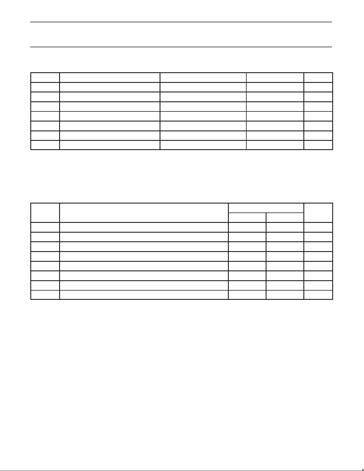
ABSOLUTE MAXIMUM RATINGS
SYMBOL
V
CC
I
IK
V
I
I
OK
V
OUT
I
OUT
T
stg
DC supply voltage –0.5 to +7.0 V
DC input diode current VI < 0 –18 mA
DC input voltage
DC output diode current VO < 0 –50 mA
DC output voltage
DC output current output in Low state 128 mA
Storage temperature range –65 to 150 °C
PARAMETER CONDITIONS RATING UNIT
3
3
1, 2
–1.2 to +7.0 V
output in Off or High state –0.5 to +5.5 V
NOTES:
1. Stresses beyond those listed may cause permanent damage to the device. These are stress ratings only and functional operation of the
device at these or any other conditions beyond those indicated under “recommended operating conditions” is not implied. Exposure to
absolute-maximum-rated conditions for extended periods may affect device reliability .
2. The performance capability of a high-performance integrated circuit in conjunction with its thermal environment can create junction
temperatures which are detrimental to reliability. The maximum junction temperature of this integrated circuit should not exceed 150°C.
3. The input and output voltage ratings may be exceeded if the input and output current ratings are observed.
RECOMMENDED OPERATING CONDITIONS
SYMBOL PARAMETER LIMITS UNIT
Min Max
V
CC
V
V
V
I
OH
I
OL
∆t/∆v Input transition rise or fall rate 0 10 ns/V
T
amb
DC supply voltage 4.5 5.5 V
Input voltage 0 V
I
High-level input voltage 2.0 V
IH
Low-level Input voltage 0.8 V
IL
High-level output current –32 mA
Low-level output current 64 mA
Operating free-air temperature range –40 +85 °C
CC
V
1998 Jun 08
5
Page 6
Philips Semiconductors Product specification
74ABT648Octal bus transceiver/register, inverting (3-State)
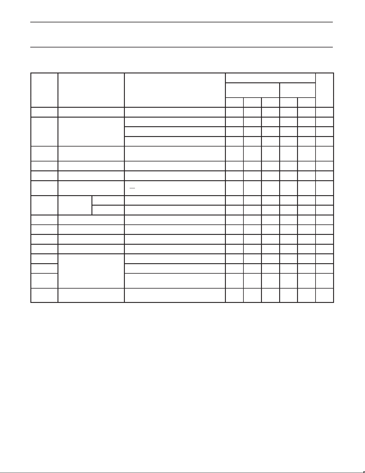
DC ELECTRICAL CHARACTERISTICS
LIMITS
T
= –40°C
SYMBOL PARAMETER TEST CONDITIONS T
amb
= +25°C
Min Typ Max Min Max
V
V
V
V
I
OFF
I
PU/IPD
Input clamp voltage VCC = 4.5V; IIK = –18mA –0.9 –1.2 –1.2 V
IK
VCC = 4.5V; IOH = –3mA; VI = VIL or V
High-level output voltage VCC = 5.0V; IOH = –3mA; VI = VIL or V
OH
VCC = 4.5V; IOH = –32mA; VI = VIL or V
Power-up output low
RST
OL
3
voltage
Low-level output voltage VCC = 4.5V; IOL = 64mA; VI = VIL or V
VCC = 5.5V; IO = 1mA; VI = GND or V
IH
IH
IH
CC
IH
2.5 3.2 2.5 V
3.0 3.7 3.0 V
2.0 2.3 2.0 V
0.13 0.55 0.55 V
0.42 0.55 0.55 V
Power-off leakage current VCC = 0.0V; VI or VO ≤ 4.5V ±5.0 ±100 ±100 µA
Power–up/down 3-State
output current
I
Input leakage Control pins VCC = 5.5V; VI = GND or 5.5V ±0.01 ±1.0 ±1.0 µA
I
4
VCC = 2.1V; VO = 0.5V; VI = GND or VCC;
VOE = Don’t care
±5.0 ±50 ±50 µA
current Data pins VCC = 5.5V; VI = GND or 5.5V ±5 ±100 ±100 µA
IIH + I
IIL + I
I
CEX
I
CCH
I
CCL
I
CCZ
∆I
3-State output High current VCC = 5.5V; VO = 2.7V; VI = VIL or V
OZH
3-State output Low current VCC = 5.5V; VO = 0.5V; VI = VIL or V
OZL
Output high leakage current VCC = 5.5V; VO = 5.5 V; VI = GND or V
I
O
Output current
1
VCC = 5.5V; VO = 2.5V –50 –65 –180 –50 –180 mA
VCC = 5.5V; Outputs High, VI = GND or V
Quiescent supply current VCC = 5.5V; Outputs Low, VI = GND or V
VCC = 5.5V; Outputs 3-State;
Additional supply current per
CC
input pin
2
VI = GND or V
VCC = 5.5V; one input at 3.4V,
other inputs at VCC or GND; VCC = 5.5V
CC
IH
IH
CC
CC
CC
5.0 50 50 µA
–5.0 –50 –50 µA
5.0 50 50 µA
110 250 250 µA
20 30 30 mA
110 250 250 µA
0.3 1.5 1.5 mA
NOTES:
1. Not more than one output should be tested at a time, and the duration of the test should not exceed one second.
2. This is the increase in supply current for each input at 3.4V.
3. For valid test results, data must not be loaded into the flip-flops (or latches) after applying the power.
4. This parameter is valid for any V
transition time of up to 100µsec is permitted.
between 0V and 2.1V , with a transition time of up to 10msec. From VCC = 2.1 to VCC = 5V ± 10% a
CC
amb
to +85°C
UNIT
1998 Jun 08
6
Page 7
Philips Semiconductors Product specification
74ABT648Octal bus transceiver/register, inverting (3-State)
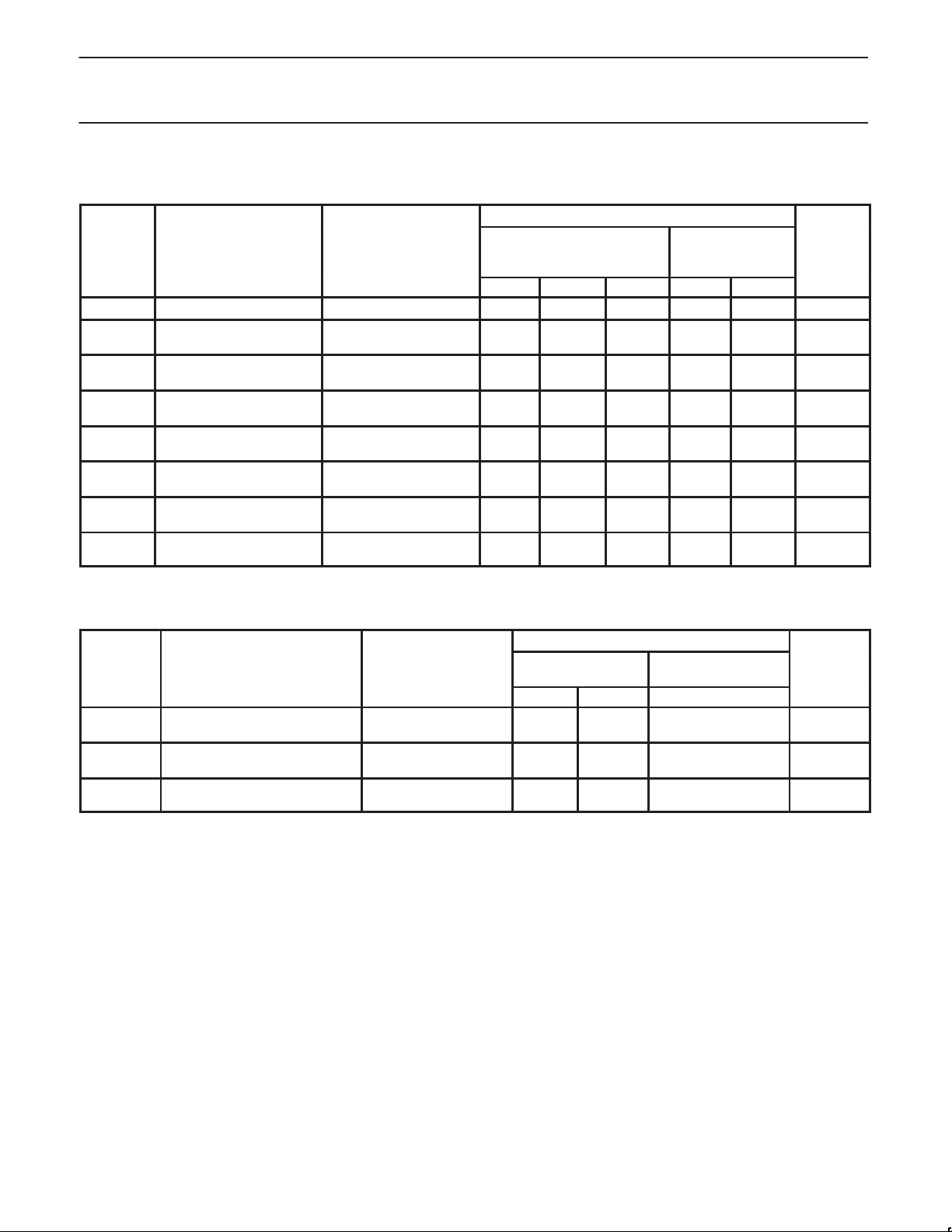
AC CHARACTERISTICS
GND = 0V, tR = tF = 2.5ns, CL = 50pF, RL = 500Ω
LIMITS
T
= -40 to
SYMBOL PARAMETER WAVEFORM
f
MAX
t
PLH
t
PHL
t
PLH
t
PHL
t
PLH
t
PHL
t
PZH
t
t
PHZ
t
t
PZH
t
t
PHZ
t
PZL
PLZ
PZL
PLZ
Maximum clock frequency 1 125 200 125 MHz
Propagation delay
CPAB to Bn or CPBA to An
Propagation delay
An to Bn or Bn to An
Propagation delay
SAB to Bn or SBA to An
Output enable time
OE to An or Bn
Output disable time
OE to An or Bn
Output enable time
DIR to An or Bn
Output disable time
DIR to An or Bn
1
2
3
2
3
5
6
5
6
5
6
5
6
T
= +25oC
amb
VCC = +5.0V
Min Typ Max Min Max
2.2
1.7
1.0
1.5
1.5
1.5
1.0
2.1
1.5
1.5
1.2
2.5
1.5
1.5
5.3
5.9
3.6
4.2
4.9
5.4
4.3
5.5
6.2
6.0
4.8
6.0
5.9
6.3
6.8
7.4
5.1
5.6
6.1
6.9
5.3
7.4
7.3
7.0
5.7
9.0
6.7
7.2
amb
+85oC
VCC = +5.0V ±0.5V
2.2
1.7
1.0
1.5
1.5
1.5
1.0
2.1
1.5
1.5
1.2
2.5
1.5
1.5
7.8
8.4
6.1
6.3
7.1
7.7
6.3
8.8
8.3
7.5
6.7
9.5
7.7
8.2
UNIT
ns
ns
ns
ns
ns
ns
ns
AC SETUP REQUIREMENTS
GND = 0V, tR = tF = 2.5ns, CL = 50pF, RL = 500Ω
SYMBOL PARAMETER WAVEFORM
ts(H)
ts(L)
th(H)
th(L)
tw(H)
tw(L)
Setup time
An to CPAB, Bn to CPBA
Hold time
An to CPAB, Bn to CPBA
Pulse width, High or Low
CPAB or CPBA
4
4
1
LIMITS
T
= +25oC
amb
VCC = +5.0V
T
= -40 to +85oC
amb
VCC = +5.0V ±0.5V
Min Typ Min
3.0
3.0
0.0
0.0
3.5
4.0
1.5
1.0
–0.4
–1.0
2.6
1.0
3.0
3.0
0.0
0.0
3.5
4.0
UNIT
ns
ns
ns
1998 Jun 08
7
Page 8
Philips Semiconductors Product specification
74ABT648Octal bus transceiver/register, inverting (3-State)
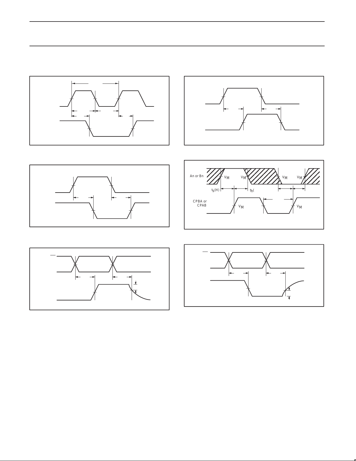
AC WAVEFORMS
VM = 1.5V, VIN = GND to 3.0V
1/f
MAX
CPBA or
CPAB
An or Bn
V
M
tw(H) tw(L)
t
PHL
V
V
M
M
V
t
M
PLH
V
M
SBA or SAB
An or Bn
V
M
t
PLH
V
M
t
PHL
V
M
V
M
An or Bn
An or Bn
SA00087
Waveform 1. Propagation Delay, Clock Input to Output, Clock
Pulse Width, and Maximum Clock Frequency
An or Bn
An or Bn
V
M
t
PHL
V
M
t
PLH
V
M
V
SBA or SAB
Bn or An
M
SA00178
Waveform 3. Propagation Delay, An to Bn or Bn to An and SBA
to An or SAB to Bn
OE
DIR
An or Bn
V
M
t
PZH
V
M
t
PHZ
–0.3V
V
V
M
OH
0V
SA00179
Waveform 5. 3-State Output Enable Time to High Level and
Output Disable Time from High Level
SA00088
Waveform 2. Propagation Delay, SAB to Bn or SBA to An
An or Bn
CPBA or
CPAB
NOTE: The shaded areas indicate when the input is permitted
to change for predictable output performance.
ts(H)
V
V
M
M
t
(H)
h
V
M
V
MVM
(L)
t
s
t
(L)
W
V
M
t
(L)
h
SA00090
Waveform 4. Data Setup and Hold Times
OE
DIR
An or Bn
V
M
t
PZL
V
M
t
PLZ
V
M
V
+0.3V
OL
SA00180
0V
Waveform 6. 3-State Output Enable Time to Low Level and
Output Disable Time from Low Level
1998 Jun 08
8
Page 9
Philips Semiconductors Product specification
74ABT648Octal bus transceiver/register, inverting (3-State)
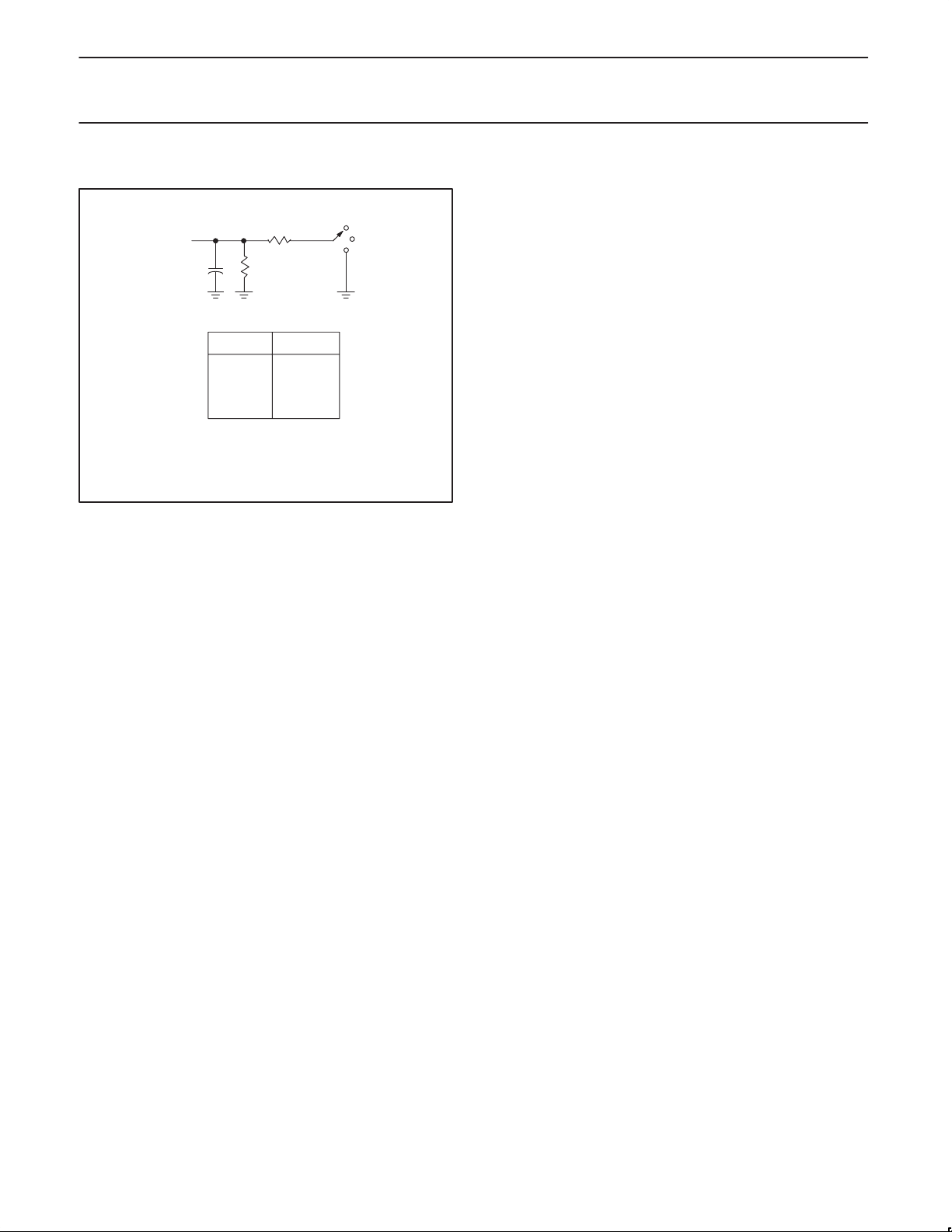
TEST CIRCUIT AND WAVEFORM
From Output
Under Test
C
= 50 pF
L
DEFINITIONS
= Load capacitance includes jig and probe capacitance;
C
L
see AC CHARACTERISTICS for value.
500 Ω
500 Ω
Load Circuit
TEST S1
t
pd
t
PLZ/tPZL
t
PHZ/tPZH
open
7 V
open
7 V
S1
GND
Open
SA00012
1998 Jun 08
9
Page 10
Philips Semiconductors Product specification
74ABT648Octal bus transceiver/register, inverting (3-State)
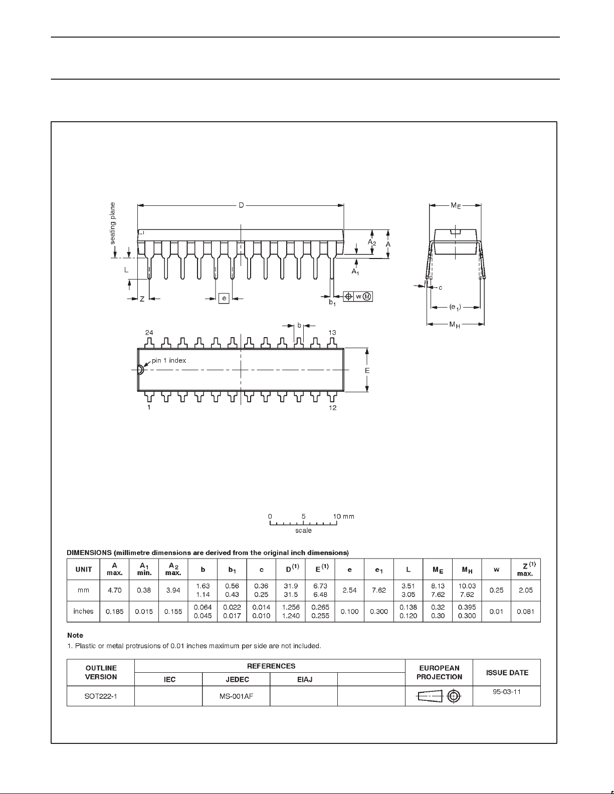
DIP24: plastic dual in-line package; 24 leads (300 mil) SOT222-1
1998 Jun 08
10
Page 11
Philips Semiconductors Product specification
74ABT648Octal bus transceiver/register, inverting (3-State)
SO24: plastic small outline package; 24 leads; body width 7.5 mm SOT137-1
1998 Jun 08
11
Page 12
Philips Semiconductors Product specification
74ABT648Octal bus transceiver/register, inverting (3-State)
SSOP24: plastic shrink small outline package; 24 leads; body width 5.3 mm SOT340-1
1998 Jun 08
12
Page 13

Philips Semiconductors Product specification
74ABT648Octal bus transceiver/register, inverting (3-State)
TSSOP24: plastic thin shrink small outline package; 24 leads; body width 4.4 mm SOT355-1
1998 Jun 08
13
Page 14

Philips Semiconductors Product specification
74ABT648Octal transceiver/register, inverting (3-State)
Data sheet status
Data sheet
status
Objective
specification
Preliminary
specification
Product
specification
Product
status
Development
Qualification
Production
Definition
This data sheet contains the design target or goal specifications for product development.
Specification may change in any manner without notice.
This data sheet contains preliminary data, and supplementary data will be published at a later date.
Philips Semiconductors reserves the right to make chages at any time without notice in order to
improve design and supply the best possible product.
This data sheet contains final specifications. Philips Semiconductors reserves the right to make
changes at any time without notice in order to improve design and supply the best possible product.
[1]
[1] Please consult the most recently issued datasheet before initiating or completing a design.
Definitions
Short-form specification — The data in a short-form specification is extracted from a full data sheet with the same type number and title. For
detailed information see the relevant data sheet or data handbook.
Limiting values definition — Limiting values given are in accordance with the Absolute Maximum Rating System (IEC 134). Stress above one
or more of the limiting values may cause permanent damage to the device. These are stress ratings only and operation of the device at these or
at any other conditions above those given in the Characteristics sections of the specification is not implied. Exposure to limiting values for extended
periods may affect device reliability.
Application information — Applications that are described herein for any of these products are for illustrative purposes only. Philips
Semiconductors make no representation or warranty that such applications will be suitable for the specified use without further testing or
modification.
Disclaimers
Life support — These products are not designed for use in life support appliances, devices or systems where malfunction of these products can
reasonably be expected to result in personal injury . Philips Semiconductors customers using or selling these products for use in such applications
do so at their own risk and agree to fully indemnify Philips Semiconductors for any damages resulting from such application.
Right to make changes — Philips Semiconductors reserves the right to make changes, without notice, in the products, including circuits, standard
cells, and/or software, described or contained herein in order to improve design and/or performance. Philips Semiconductors assumes no
responsibility or liability for the use of any of these products, conveys no license or title under any patent, copyright, or mask work right to these
products, and makes no representations or warranties that these products are free from patent, copyright, or mask work right infringement, unless
otherwise specified.
Philips Semiconductors
811 East Arques Avenue
P.O. Box 3409
Sunnyvale, California 94088–3409
Telephone 800-234-7381
Copyright Philips Electronics North America Corporation 1998
All rights reserved. Printed in U.S.A.
print code Date of release: 06-98
Document order number: 9397-750-04022
yyyy mmm dd
14
 Loading...