

Page 1
4N51, 4N52
67023
4N53, 4N54
HERMETIC , NUMERIC AND HEXADECIMAL
DISPLAYS
OPTOELECTRONIC PRODUCTS
Mii
DIVISION
Features:
Applications:
• Conforms to MIL-PRF-87157
Three character options
•
Numeric, Hexidecimal or Over range
4 X 7 dot matrix character
•
Memory latch/decoder/driver is TTL compatible
•
Available in Red or Green
•
Categorized for luminous intensity
•
High reliability systems
•
• Instrumentation panels
Communication equipment
•
Medical equipment
•
Harsh environments
•
IR blocking filter available
•
DESCRIPTION
The
4N51-4N54
an on-board decoder/driver and memory (except 4N53). These displays are hermetically sealed and conform to MIL-PRF-87157, the
general specification for light emitting diode displays. The character height is 7.4mm (.29”). The green LED version conforms to
MIL-D-87157 with exception of color.
The 4N51 is a numeric display which decodes positive BCD logic into the numbers “0-9”, a “-” sign, a right-hand decimal point, and a
test pattern (all LED’s on).
series are solid state numeric and hexidecimal displays for use in high reliability applications. The displays feature
The 4N52 is the same as the 4N51, but the decimal point is located on the left side of the device.
The 4N53 is an over range device which displays “+1” and a right-hand decimal point. This display is typically driven using external
switching transistors.
The 4N54 is a hexidecimal display which decodes positive BCD logic into 16 characters “0-9, A-F”. An input is provided to blank the
display (all LED’s off) without losing the contents of the memory.
ABSOLUTE MAXIMUM RATINGS
Storage Temperature..........................................................................................................................................-65°C to +125°C
Operating Free-Air Temperature Range. ...........................................................................................................-55°C to +100°C
Lead Solder Temperature (1/16” [1.6mm] below seating plane for 10s) ........................................................................... 260°C
Supply Voltage, V
Voltage Applied to Input Logic, DP and Enable Pins ............................................................................................... . -0.5V to 7V
Voltage Applied to Blanking Input (4N54 only)........................................................................................................... -0.5V to 7V
Forward Current, Each LED (4N53 only) ............................................................................................................................10mA
Reverse Voltage, Each LED (4N53 only).................................................................................................................................4V
(4N51, 4N52, 4N54)................................................................................................................. .-0.5V to 7V
CC
MICROPAC INDUSTRIES, INC. OPTOELECTRONIC PRODUCTS DIVISION • 725 E. Walnut St., Garland, TX 75040 • (972) 272-3571 • Fax (972) 487-6918
www.micropac.com
E-MAIL:
optosales@micropac.com
2 - 4
Page 2
4N51, 4N52,
67023
4N53, 4N54
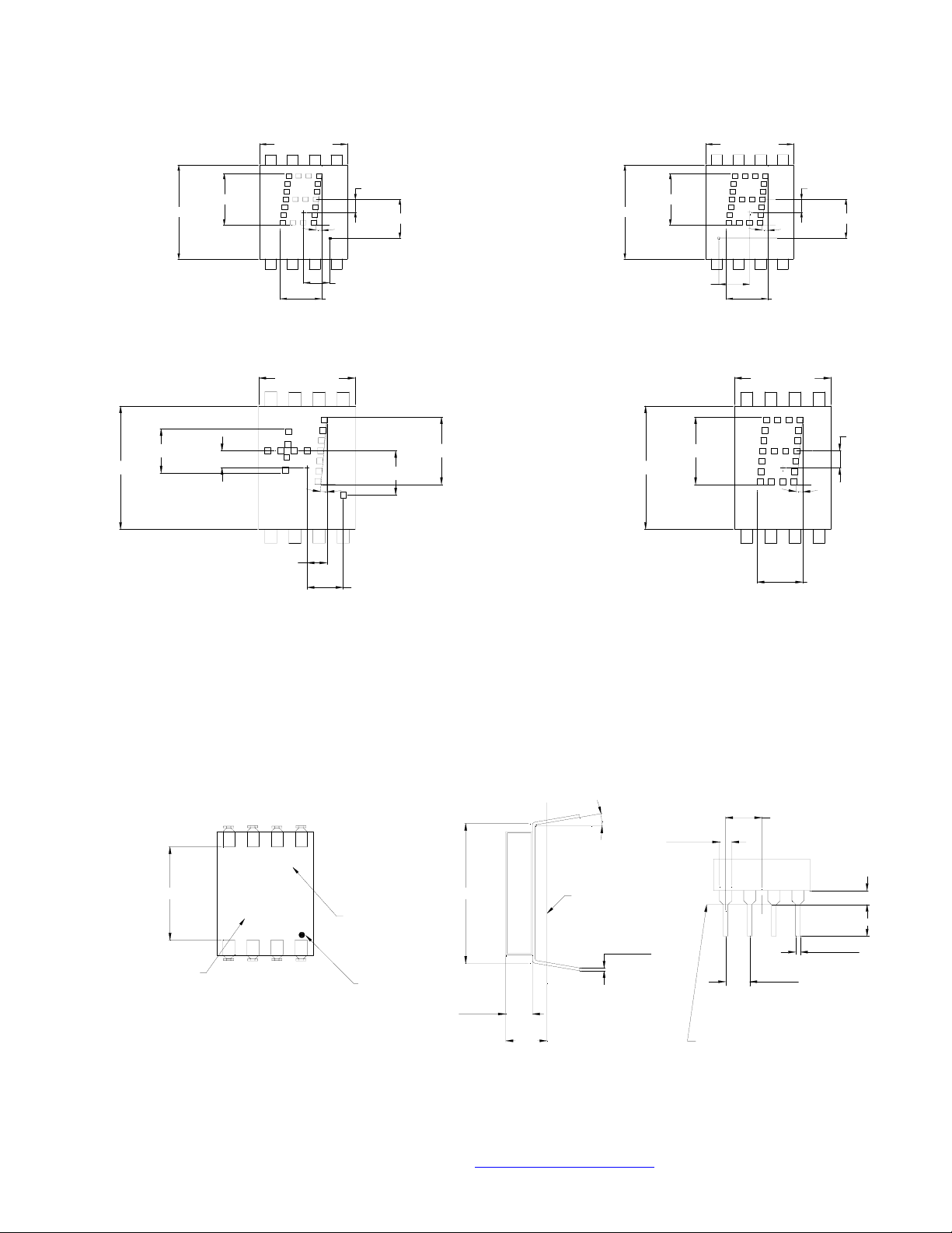
*
HERMETIC, NUMERIC AND HEXIDECIMAL DISPLAYS
0.190 [4.83]
0.530 [13.46]
0.530 [13.46]
0.290 [7.37]
0.072 [1.84]
0.400 [10.16]
4N51
0.400 [10.16]
5°
0.083 [2.11]
5°
0.120 [3.04]
0.190 [4.83]
0.150 [3.81]
0.0 73 [1 .84]
0.220 [5.59]
0.190 [4.83]
0.290 [7.36]
0.530 [13.46]
0.530 [13.46]
0.290 [7.37]
0.140 [3.56]
0.290 [7.37]
0.400 [10.16]
5°
0.190 [4.83]
4N52
0.400 [10.16]
0.073 [1.84]
0.220 [5.59]
0.073 [1.84]
5°
0.190 [4.83]
0.400 [10.16]
DATE CODE
*JEDEC Registered Data
4N53
REAR VIEW
6
5
X
Mii
XXX
YYWW
4N54
SIDE VIEW
87
LUMINOUS
INTENSITY
CATEGORY
1234
PIN 1 KEY
0.600 [15.24]
0.110
[2.79]
0.170
[4.32]
10°
SEATING PLANE
.012±.003
[0.3±0.08]
TYP
0.050
[1.27]
END VIEW
0.100±.005
[2.5±0.13]
SEATING PLANE
0.150 [3.81]
TYP
0.060 [1.52]
0.136 [3.45]
.020±.003
[0.5±0.08]
TYP
MICROPAC INDUSTRIES, INC. OPTOELECTRONIC PRODUCTS DIVISION • 725 E. Walnut St., Garland, TX 75040 • (972) 272-3571 • Fax (972) 487-6918
www.micropac.com
E-MAIL:
optosales@micropac.com
2 - 5
Page 3
4N51, 4N52,
67023
4N53, 4N54
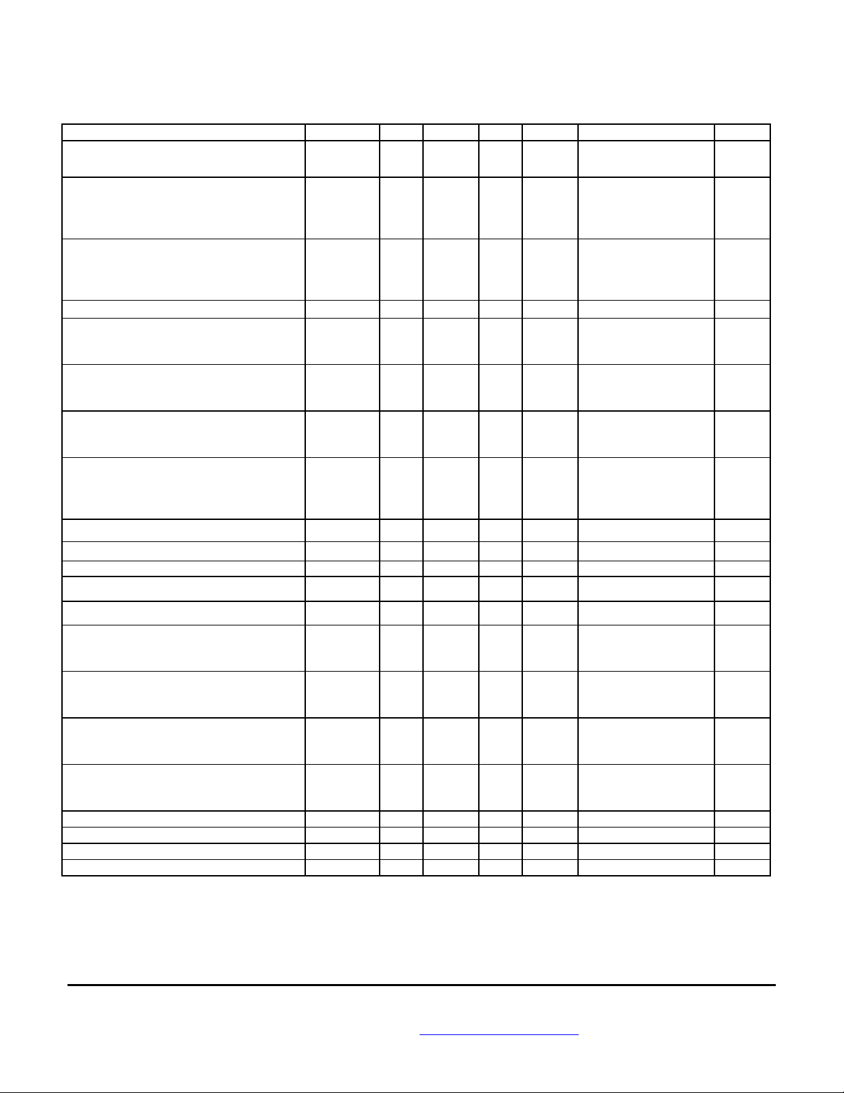
*ELECTRICAL OPTICAL CHARACTERISTICS
TA = -55°C to +100°C unless otherwise specified.
PARAMETER SYMBOL MIN TYP MAX UNITS TEST CONDITIONS NOTE
Supply Current 4N51
Power Dissipation 4N51
4N53
4N54
Luminous Intensity per LED 4N51
4N52
4N53
4N54
Forward Voltage per LED 4N53 V
Logic Low-Level Input Voltage 4N51
4N52
4N54
Logic Low-Level Input Voltage 4N51
4N52
4N54
Enable Low-Voltage; Data Being Entered 4N51
4N52
4N54
Enable High-Voltage; data not being
entered 4N51
4N52
4N54
Blanking Low-Voltage display not blanked 4N54
Blanking High-Voltage display blanked 4N54
Leak Rate ALL 5x10
Blanking Low-Level Input Current 4N54 I
Blanking High-Level Input Current 4N54 I
Logic Low-Level Input Current 4N51
4N52
4N54
Logic High-Level Input Current 4N51
4N52
4N54
Enable Low-Level Input Current 4N51
4N52
4N54
Enable High-Level Input Current 4N51
4N52
4N54
Wavelength at Peak Emission ALL
Dominant Wavelength ALL d 640 t
Forward Voltage per LED 4N53 V
Weight ALL 1 gm
NOTES:
1. All typical values at VCC = 5.0 volts, t
2. Luminous intensity for a specific temperature may be calculated with the following relationship: I
3. The dominant wavelength ,
λ
d
diagram.
For 4N53 test conditions, I
4.
*JEDEC Registered Data
= 10mA, all diodes lit.
F
4N52
4N54
4N52
= 25°C.
A
is a single wavelength that defines the saturated color of monochromatic light, as derived from the CIE chromaticity
I
CC
P
T
I
V
F
V
IL
V
IH
V
EL
V
EH
V
BL
V
BH
BL
BH
I
IL
I
IH
I
EL
I
EH
λ
P
F
HERMETIC, NUMERIC AND HEXIDECIMAL DISPLAYS
112
112
112
560
560
280
560
40
40
45
40
85
85
85
85
1.6 2.0 V I
2
2
2
2
2
2
3.5 V
655 nm t
1.6 2.0 V IF = 10mA
170
170
mA
170
935
935
mW V
320
935
µ
cd
0.8
0.8
VV
0.8
VV
0.8
0.8
VV
0.8
VV
0.8 V
-8
50 mA V
1.0 mA V
-1.6 mA V
+100
µ
AV
-1.6 mA V
+130
µ
AV
(tA) = I
V
V
(25°C) (.985) [t
Numeral 5 and DP lighted
Numeral 5 and DP lighted
V
CC
V
CC
I
F
V
CC
CC
CC
CC
CC
CC
CC
V
= 5.5V
CC
= 5.5V
CC
= 5V, T
= 5V, T
= 10mA,
= 5V, A = 25°C
= 10mA
F
= 4.5V
CC
= 4.5V
CC
= 4.5V
CC
= 4.5V
CC
V
= 4.5V
CC
V
= 4.5V
CC
A
A
A
= 25°C
= 25°C
= 25°C
1
1,4
2
cc/sec
= 5.5V, VBL = 0.8V
= 5.5V, VBH = 4.5V
= 5.5V, VIL = 0.4V
= 5.5V, VIH = 2.4V
= 5.5V, V
= 5.5V, V
= 0.4V
EL
= 2.4V
EH
= 25°C
A
= 25°C3
A
- 25°C].
A
MICROPAC INDUSTRIES, INC. OPTOELECTRONIC PRODUCTS DIVISION • 725 E. Walnut St., Garland, TX 75040 • (972) 272-3571 • Fax (972) 487-6918
www.micropac.com
E-MAIL:
optosales@micropac.com
2 - 6
Page 4

67023
4N51, 4N52,
4N53, 4N54
Supply Voltage 4N51
4N52
4N53
4N54
Operating Temperature ALL t
Enable Pulse Width 4N51
4N52
4N54
Time data must be held before positive 4N51
transition of enable line 4N52
4N54
Time data must be held after positive 4N51
transition of enable line 4N52
4N54
Enable pulse rise time 4N51
4N52
4N54
Forward Current 4N53 I
*RECOMMENDED OPERATING CONDITIONS:
PARAMETER SYMBOL MIN MAX UNITS
HERMETIC, NUMERIC AND HEXIDECIMAL DISPLAYS
V
CC
A
t
W
t
SETUP
t
HOLD
t
TLH
F
4.5
4.5
NA
4.5
-55 100
100 ns
50 ns
50 ns
510m
5.5
5.5
NA
5.5
200 ns
NA
V
V
V
°
C
67023-001
67023-101
67023-101C
67023-002
67023-102
67023-102C
67023-003
67023-103
67023-103C
67023-004
67023-104
67023-104C
67023-034
67023-315
NOTES:
1. When ordering DSCC part numbers, you may order by the MII part number or the DSCC part number.
2. The first X at the end of M87157/0010XA[X]X designates lead finish. In place of the X use A for hot solder dip
or C for gold finish.
3. Second X at the end of the M87157/0010XAX[X] designates luminous intensity code. In place of the X use C
thru K to indicate desired intensity level.
4N51 Commercial (0
4N51 Screened to TXV level (-55° to +100°C) with 100% screening.
4N51 marked with DSCC P/N JM87157/00101AXX (-55° to +100°C) with 100% screening.
4N52 Commercial (0
4N52 Screened to TXV level (-55
4N52 marked with DSCC P/N JM87157/00102AXX (-55° to +100°C) with 100% screening.
4N53 Commercial (0
4N53 Screened to TXV level (-55° to +100°C) with 100% screening.
4N53 marked with DSCC P/N JM87157/00103AXX (-55° to +100°C) with 100% screening.
4N54 Commercial (0
4N54 Screened to TXV level (-55° to +100°C) with 100% screening.
4N54 marked with DSCC P/N JM87157/00104AXX (-55° to +100°C) with 100% screening.
4N54, green commercial (0
4N54, green Mil-Temp (-55° to +100°C) with 100% screening.
°
to
70°C)
°
to
70°C)
°
to
70°C)
°
to
70°C)
°
SELECTION GUIDE
°
to +100°C) with 100% screening.
to
70°C)
*JEDEC Registered Data
MICROPAC INDUSTRIES, INC. OPTOELECTRONIC PRODUCTS DIVISION • 725 E. Walnut St., Garland, TX 75040 • (972) 272-3571 • Fax (972) 487-6918
www.micropac.com
E-MAIL:
optosales@micropac.com
2 - 7
Page 5

67023
4N51, 4N52,
4N53, 4N54
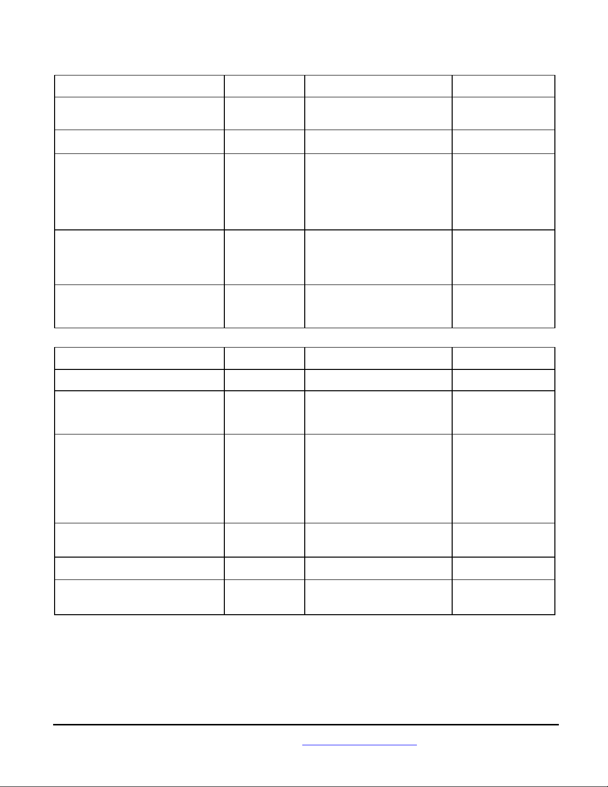
4N51, 4N52, 4N54 Logic
HERMETIC, NUMERIC AND HEXIDECIMAL DISPLAYS
1.5V
t
90%
t
HOLD
1.5V
1.5V
LH
LED MATRIX
MATRIX
DECODER
t
PIN NO.
7
5
8
1
2
3
4
CONTROL
4
6
1.5V
SETUP
1.5V
1.5V
DC1
DC2
DC4
DC8
DP
10%
t
W
LATCH
MEMORY
DP
LED MATRIX
DRIVER
DATA INPUT
(LOW LEVEL DATA)
DATA INPUT
(HIGH LEVEL DATA)
ENABLE
INPUT
FIGURE 1 Timing Diagram of 4N51, 4N52 and 4N54 Series Logic
Vcc
ENABLE
LOGIC
INPUT
DP (2)
BLANKING (3)
GROUND
FIGURE 2 Block Diagram of 4N51, 4N52 and 4N54 Series Logic
TRUTH TABLE
(1)
X
1
4N51/4N52
X
2
4
4N54
X
8
BCD DATA
X
LLLL
HLLL
LHLL
HHLL
LLHL
HLHL
LHHL
HHHL
LLLH
HLLH
LHLH
(BLANK)
HHLH
(BLANK)
LLHH
.....
HLHH
(BLANK)
(2)
LHHH
ON
OFF
LOAD DATA
LATCH DATA
DISPLAY ON
DISPLAY OFF
V
DP
V
DP
V
E
V
E
V
B
V
HHHH
DECIMAL PT.
(1)
ENABLE
BLANKING
NOTES:
1. H = Logic High: L = Logic Low. With the
enable input at logic high changes in BCD
input levels or D.P. input have no effect
upon display memory, displayed character,
or D.P.
2. The decmal point, DP, pertains only to
the 4n51 and 4n52 displays.
3. The blanking control, B, pertains only
to the 4n54 hexadecimal display.
Blanking input has no effect upon memory.
(3)
00
11
22
33
44
55
66
77
88
99
A
B
C
D
E
F(BLANK)
=L
=H
=L
=H
=L
=H
B
4N53 Over Range Character
7
Vcc
dp
4
MINUS PLUS
8 1
PIN
1
2
3
4
5
6
7
8
FUNCTION
Plus
Numeral One
Numeral One
DP
Open
Open
Vcc
Minus/Plus
NUMERAL ONE
32
580 100
FIGURE 3
TYPICAL DRIVING CIRCUIT
MICROPAC INDUSTRIES, INC. OPTOELECTRONIC PRODUCTS DIVISION • 725 E. Walnut St., Garland, TX 75040 • (972) 272-3571 • Fax (972) 487-6918
www.micropac.com
E-MAIL:
PLUS
150580 150
TRUTH TABLE FOR TYPICAL DRIVING CIRCUIT
optosales@micropac.com
2 - 8
CHARACTER
+
-
1
DECIMAL POINT
BLANK
PIN
1
2,3X4
H
X
L
X
XX
HX
HXX
LLL
NOTES:
L: Line switching transistor in figure 3 cutoff.
H: Line transistor in figure 3 satuated
X: Don't Care.
8
H
H
X
X
L
Page 6

67023
4N51, 4N52,
4N53, 4N54
HERMETIC, NUMERIC AND HEXIDECIMAL DISPLAYS
PART MARKING SYSTEM
PREFERRED PART NUMBER SYSTEM MII PART NUMBERS
Standard Product With Tables I, II, III and IV Quality Level A TXV
Tables I, II
4N51 M87157/00101XXX 67023-201
67023-101 67023-001
4N52 M87157/00102XXX 67023-202 67023-102 67023-002
4N53 M87157/00103XXX 67023-203 67023-103 67023-003
4N54 M87157/00104XXX 67023-204 67023-104 67023-004
TABLE I
100% SCREENING – CLASS A OF MIL-PRF-87157
Test Screen MIL-PRF-750
Method Conditions
1. Precap Visual 2072
Commercial
Table II, Subgroups I, VII
2. High Temperature Storage 1032
TA = 125°C, Time = 24 hours
3. Temperature Cycling 1051 Condition B, 10 Cycles, 15 Min. Dwell
4. Constant Acceleration 2006
10,000 G’s at Y1 orientation
5. Fine Leak 1071 Condition H
6. Gross Leak 1071 Condition C
7. Interim Electrical / Optical Tests
8. Burn-In
(1,3)
(2)
------
1015
IV, ICC, IBL, IBH, IEL, IEH, IIL, and I
IH
TA = 25°C
Condition B at VCC = 5V and cycle through
logic at 1 character per second.
T
= 100°C, t = 160 hours
A
∆IV = 20%, ∆ICC = ±10 mA, ∆IIH = ±10 µA
and ∆IEH = ±13µA
9. Final Electrical Test
(2)
------ Same as Step 7
10. Delta Determinations ------
11. External Visual
(1)
2009
TABLE II
GROUP A ELECTRICAL TEST – CLASS A OF MIL-PRF-87157
Test Parameters LTPD
Subgroup 1
DC Electrical Test at 25°C
(2)
IV, ICC, IBL, IBH, IEL, IEH, IIL, and IIH and
5
visual function, TA = 25°C
Subgroup 2
DC Electrical Tests at High
Temperature
(2)
Same as Subgroup 1, except delete IV and visual
function. TA = +100°C
7
Subgroup 3
DC Electrical Tests at Low
Temperature
(2)
Same as Subgroup 1, except delete IV and visual
function. TA = -55°C
7
Subgroup 4, 5 and 6 not tested
Subgroup 7
Optical and Functional Tests
Satisfied by Subgroup 1 5
at 25°C.
Subgroup 8
External Visual 7
MICROPAC INDUSTRIES, INC. OPTOELECTRONIC PRODUCTS DIVISION • 725 E. Walnut St., Garland, TX 75040 • (972) 272-3571 • Fax (972) 487-6918
www.micropac.com
E-MAIL:
optosales@micropac.com
2 - 9
Page 7
4N51, 4N52,
67023 4N53, 4N54 HERMETIC, NUMERIC AND HEXIDECIMAL DISPLAYS
GROUP B, CLASS A AND B OF MIL-PRF-87157
Test MIL-PRF-750
Method
Subgroup 1
Resistance to Solvents 1022 4 Devices / 0 Failures
Internal Visual and Mechanical
Subgroup 2
(1,2)
(10)
2075 1 Device / 0 Failures
Solderability 2026
Subgroup 3
Thermal Shock (Temp. Cycle) 1051 Condition B1, 15 Min. Dwell LTPD = 15
Moisture Resistance
(3)
1021
Fine Leak 1071 Condition H
Gross Leak 1071 Condition C
Electrical / Optical Endpoints
Subgroup 4
Operating Life Test (340 hrs.)
Electrical / Optical Endpoints
(4)
(5)
(4)
------
1027
------ Same as Subgroup 3
Subgroup 5
Non-operating (Storage) Life
Test (340 hrs.)
Electrical / Optical Endpoints
(4)
GROUP C, CLASS A AND B OF MIL-PRF-87157
1032
------ Same as Subgroup 3
Test MIL-PRF-750
Method
Subgroup 1
Physical Dimensions 2066 2 Devices / 0 Failures
Subgroup 2
(2, 10)
Lead Integrity 2004 Condition B2
Fine Leak 1071 Condition H
Gross Leak 1071 Condition C
Subgroup 3
Shock 2016 1500G, Time = 0.5 ms, 5 blows in
Vibration, Variable Frequency 2056
Constant Acceleration 2006
External Visual
Electrical / Optical Endpoints
Subgroup 4
Salt Atmosphere 1041 LTPD = 15
External Visual
Subgroup 5
Bond Strength
Subgroup 6 LTPD = 10
Operating Life Test
Electrical / Optical Endpoints
NOTES: 1. Whenever electrical/optical tests are not required as endpoints, electrical rejects may be used.
2. The LTPD applies to the number of leads inspected, except in no case shall less than 3 displays be used to provide the number of leads required.
3. Initial conditioning should be a 15” bend inward one cycle.
4. Limits and conditions are per the electrical/optical characteristics.
5. Burn-in for the over range shall use Condition B at a nominal I
6. Solderability samples shall not be used.
7. Visual requirements shall be as specified in MIL-PRF-883, Methods 1010 or 1011.
8. Displays may be selected prior to seal.
9. If a given inspection lot, undergoing Group B inspection, has been selected to satisfy the Group C inspection requirements, the 340 hour life tests may
be continued on test to 1000 hours in order to satisfy the Group C Life Test requirements. In such cases, either the 340 hour endpoint measurements
shall be made a basis for Group B lot acceptance or the 1000 hour endpoint measurement shall be used as the basis for both Group B and Group C
acceptance.
10. MIL-PRF-883 test method applies.
MICROPAC INDUSTRIES, INC. OPTOELECTRONIC PRODUCTS DIVISION • 725 E. Walnut St., Garland, TX 75040 • (972) 272-3571 • Fax (972) 487-6918
(1,6)
(7)
(4)
(7)
(8)
(9)
(4)
www.micropac.com
1010 or 1011
------
1010 or 1011
2037 Condition A LTPD = 20 (c = 0)
1026
------ Same as Subgroup 3
TABLE III
Conditions Sample Size
TA = 245°C for 5 seconds
IV, ICC, IBL, IBH, IEL, IEH, IIL, I
visual function. TA = 25°C
TA = 100°C, at VCC = 5.0V and
cycling through logic at 1 character
per second.
TA = 125°C
TABLE IV
Conditions Sample Size
each orientation X
10,000G at Y1 orientation
IV, ICC, IBL, IBH, IEL, IEH, IIL, I
visual function. TA = 25°C
TA = +100°C 1000 HRS
= 8 mA with “+1” illuminated for t=340 hours.
F
E-MAIL:
optosales@micropac.com
, Y1, Z
1
LTPD = 15
and
IH
LTPD = 10
LTPD = 10
LTPD = 15
LTPD = 15
1
and
IH
2 - 10
 Loading...