

Page 1
High Speed Super Low Power SRAM
8K-Word By 8 Bit HM6264
Revision History
Rev. No. History Issue Date Remark
1.0 Initial Issue Jan..19 ,2005
Rev. 1.0
MCU reserves the right to change product or specification without notice.
1
Page 2
High Speed Super Low Power SRAM
8K-Word By 8 Bit HM6264
GENERAL DESCRIPTION
The HM6264 is a high performance, high speed and super low power CMOS Static Random Access
Memory organized as 8,192 words by 8bits and operates from a single 4.5V to 5.5V supply voltage.
Advanced CMOS technology and circuit techniques provide both high speed, super low power features and
maximum access time of 70ns in 5.0V operation. Easy memory expansion is provided by using two chip
enable inputs (/CE1, CE2) and active LOW output enable (/OE).
The HM6264 has an automatic power down feature, reducing the power consumption significantly when
chip is deselected. The HM6264 is available in JEDEC standard 28-pin SOP(300 mil) and PDIP (600 mil)
packages.
FEATURES
Operation voltage : 4.5 ~ 5.5V
Ultra low power consumption:
Operating current 1mA@1MHz & CMOS standby current 1.0uA (Typ.) in Vcc=5.0V
High speed access time: 70ns.
Automatic power down when chip is deselected.
Three state outputs and TTL compatible.
Data retention supply voltage as low as 2.0V.
Easy expansion with /CE1, CE2 and /OE options.
PRODUCT FAMILY
Product Family Operating Temp. Vcc Range Speed (ns)
HM6264 0~70oC 4.5~5.5V 70 1.0uA
Standby Current (Typ.)
I
CCSB1
Package Type
28 SOP
28 PDIP
Rev. 1.0
MCU reserves the right to change product or specification without notice.
2
Page 3
High Speed Super Low Power SRAM
8K-Word By 8 Bit HM6264
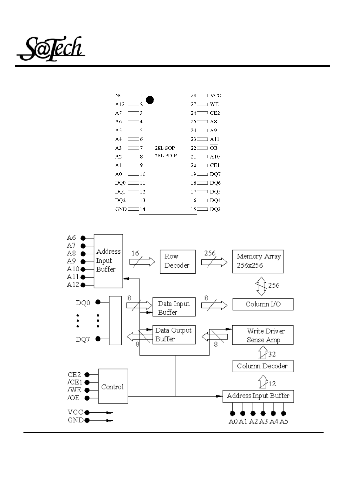
PIN CONFIGURATIONS
FUNCTIONAL BLOCK DIAGRAM
Rev. 1.0
MCU reserves the right to change product or specification without notice.
3
Page 4
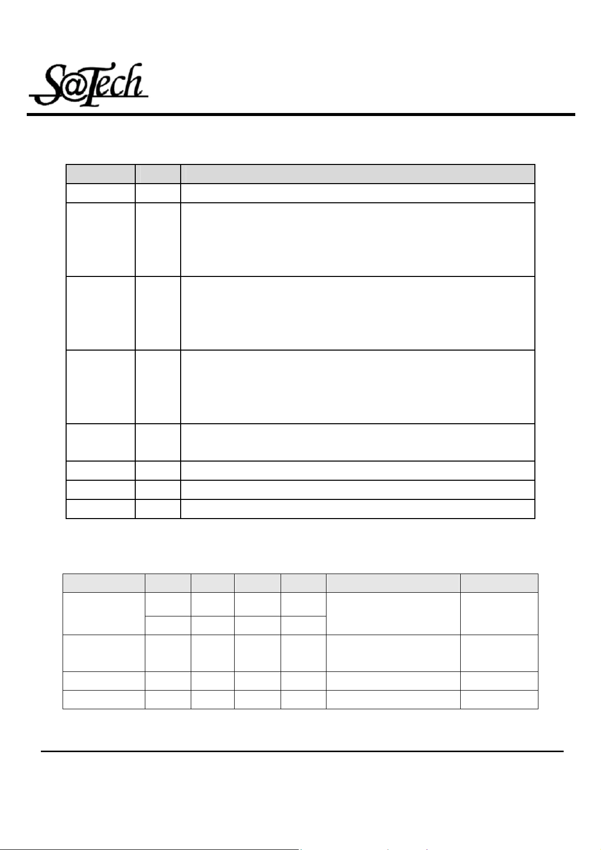
PIN DESCRIPTIONS
Name Type Function
High Speed Super Low Power SRAM
8K-Word By 8 Bit HM6264
A0 – A12
/CE1, CE2
/WE
/OE
DQ0~DQ7
Vcc
Input Address inputs for selecting one of the 8,192 x 8 bit words in the RAM
/CE1 is active LOW and CE2 is active HIGH. Both chip enables must be
active when data read from or write to the device. If either chip enable is not
Input
active, the device is deselected and in a standby power down mode. The DQ
pins will be in high impedance state when the device is deselected.
The Write enable input is active LOW. It controls read and write operations.
With the chip selected, when /WE is HIGH and /OE is LOW, output data will
Input
be present on the DQ pins, when /WE is LOW, the data present on the DQ
pins will be written into the selected memory location.
The output enable input is active LOW. If the output enable is active while the
chip is selected and the write enable is inactive, data will be present on the
Input
DQ pins and they will be enabled. The DQ pins will be in the high impedance
state when /OE is inactive.
These 8 bi-directional ports are used to read data from or write data into the
I/O
RAM.
Power Power Supply
Gnd
NC
Power Ground
No connection
TRUTH TABLE
MODE /CE1 CE2 /WE /OE DQ0~7 Vcc Current
H X X X
Standby
High Z I
CCSB
, I
CCSB1
X L X X
Output
L H H H High Z ICC
Disable
Read
Write
L H H L D
L H L X D
I
OUT
I
IN
CC
CC
Rev. 1.0
MCU reserves the right to change product or specification without notice.
4
Page 5
High Speed Super Low Power SRAM
8K-Word By 8 Bit HM6264
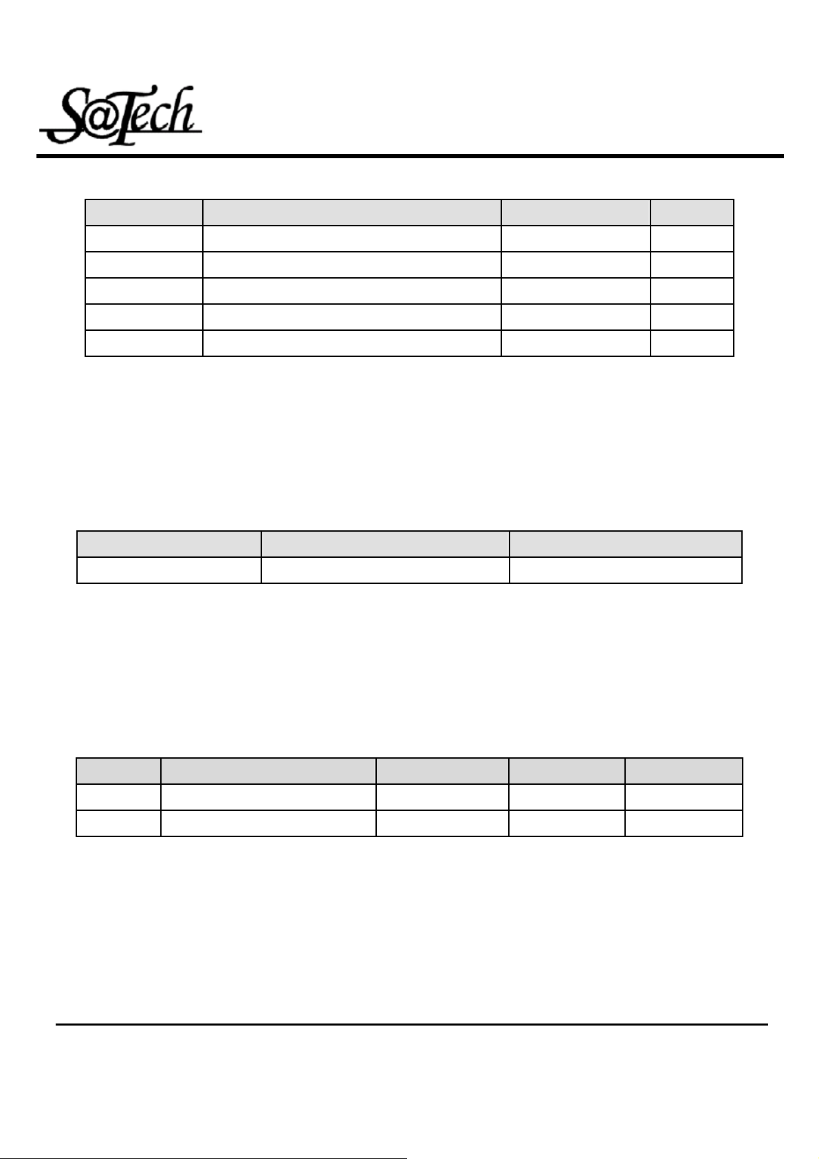
ABSOLUTE MAXIMUM RATINGS
Symbol Parameter Rating Unit
(1)
V
TERM
T
BIAS
T
STG
PT
I
OUT
1. Stresses greater than those listed under ABSOLUTE MAXIMUM RATINGS may cause permanent damage to
the device. This is a stress rating only and functional operation of the device at these or any other conditions
above those indicated in the operational sections of this specification is not implied. Exposure to absolute
maximum rating conditions for extended periods may affect reliability.
Terminal Voltage with Respect to GND -0.5 to Vcc+0.5 V
Temperature Under Bias -40 to +125
Storage Temperature -65 to +150
Power Dissipation 1.0 W
DC Output Current 50 mA
OPERATING RANGE
Range
Commercial
Ambient Temperature
o
0~70
C
4.5 ~ 5.5V
Vcc
O
C
O
C
CAPACITANCE
Symbol Parameter Conduction MAX. Unit
CIN
CDQ
1.This parameter is guaranteed, and not 100% tested.
(1)
(TA=25℃,f=1.0MHz)
Input Capacitance VIN=0V 8 pF
Input/Output Capacitance VDI/O=0V 10 pF
Rev. 1.0
MCU reserves the right to change product or specification without notice.
5
Page 6
High Speed Super Low Power SRAM
8K-Word By 8 Bit HM6264
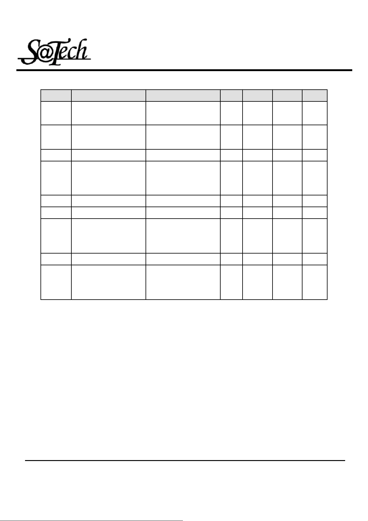
DC ELECTRICAL CHARACTERISTICS (TA = 0
Name Parameter Test Condition MIN TYP
o
~70oC, Vcc = 5.0V))
(1)
MAX Unit
VIL
VIH
IIL
IOL
VOL
VOH
ICC
I
CCSB
I
CCSB1
Guaranteed Input Low
Voltage
Guaranteed Input High
Voltage
Input Leakage Current VCC=MAX, VIN=0 to VCC
Output Leakage Current
Output Low Voltage VCC=MAX, I
Output High Voltage VCC=MIN, I
Operating Power Supply
Current
TTL Standby Supply /CE1=VIH, IDQ=0mA,
CMOS Standby Current
(2)
(2)
Vcc=5.0V
Vcc=5.0V
VCC=MAX, /CE1=VIh, or
CE2= V
VIL VIO=0V to VCC
/CE1=VIL, IDQ=0mA,
F=F
/CE1≧VCC-0.2V, CE2= 0.2V,
VIN≧VCC-0.2V or VIN≦0.2V,
MAX
or /OE=V
IL,
OL
OH
=1/ tRC
= 1mA
= -1mA
Ih, or
/WE=
-0.5 0.8
2.2 Vcc+0.5
-1 1
-1 1
0.4
2.4
30
10
1 10
V
V
uA
uA
V
V
mA
mA
uA
1. Typical characteristics are at TA = 25oC.
2. These are absolute values with respect to device ground and all overshoots due to system or tester notice are
included.
Rev. 1.0
MCU reserves the right to change product or specification without notice.
6
Page 7
High Speed Super Low Power SRAM
8K-Word By 8 Bit HM6264
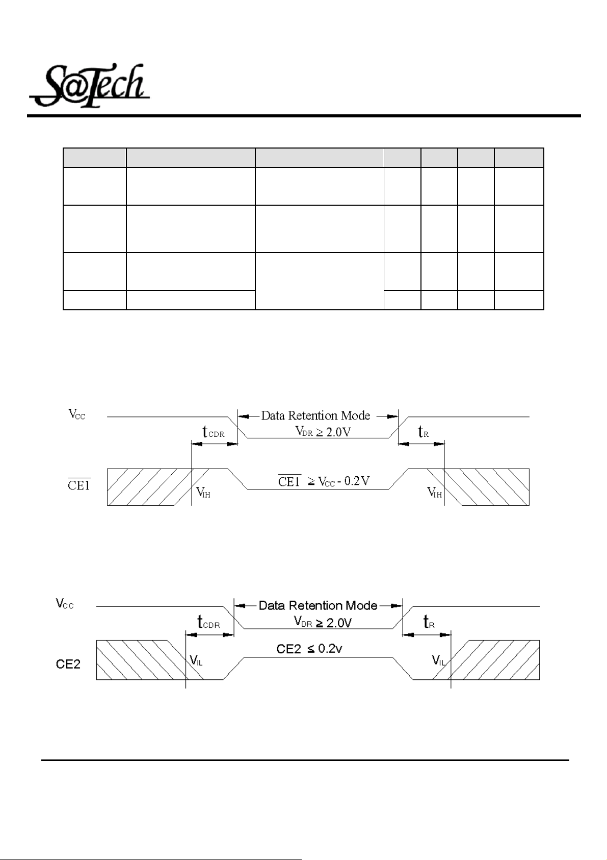
DATA RETENTION CHARACTERISTICS (TA = 0
Name Parameter Test Condition MIN TYP
o
~70oC, Vcc = 5.0V))
(1)
MAX Unit
VDR
I
CCDR
T
CDR
tR Operation Recovery Time
1.TA = 2 5oC
2. t
Read Cycle Time
RC= .
for Data Retention
V
CC
Data Retention Current
Chip Deselect to Data
Retention Time
/CE1 ≧ V
V
-0.2V or VIN≦0.2V
CC
/CE1≧V
V
-0.2V or VIN≦0.2V
CC
Retention Waveform
-0.2V, VIN≧
CC
-0.2V, VIN≧
CC
Refer to
LOW Vcc DATA RETENTION WAVEFORM(1)
2.0 V
0.5 5
0 ns
t
(2)
RC
( /CE1 Controlled )
ns
uA
LOW Vcc DATA RETENTION WAVEFORM (2) ( CE2 Controlled )
Rev. 1.0
MCU reserves the right to change product or specification without notice.
7
Page 8
High Speed Super Low Power SRAM
8K-Word By 8 Bit HM6264
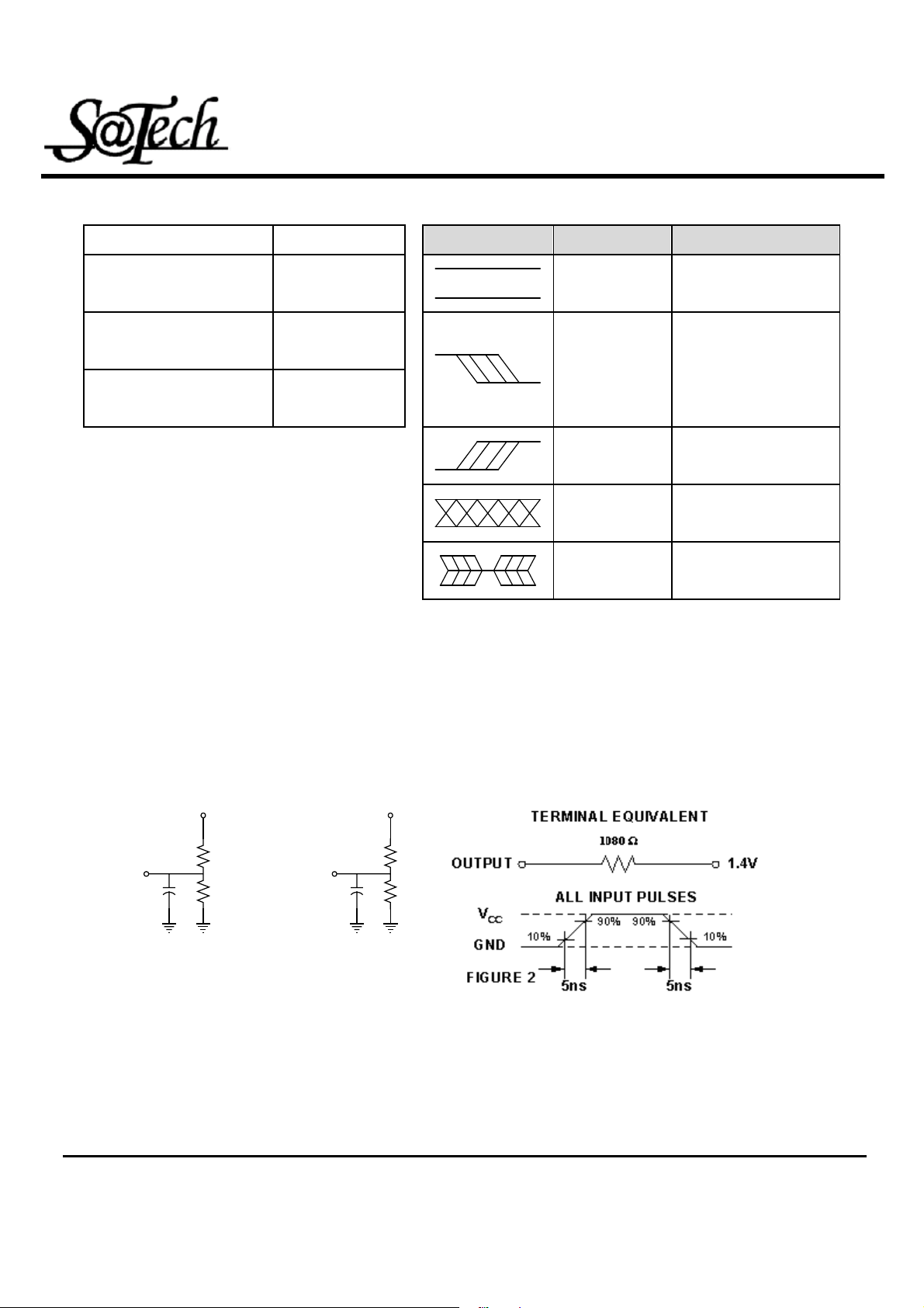
AC TEST CONDITIONS KEY TO SWITCHING WAVEFORMS
Input Pulse Levels Vcc/0V
Input Rise and Fall Times 5ns
WAVEFORMS INPUTS OUTPUTS
MUST BE STEADY MUST BE STEADY
Input and Output Timing
0.5Vcc
Reference Level
See FIGURE 1A
MAY CHANGE
FROM H TO L
Output Load
and 1B
MAY CHANGE
FROM L TO H
DON’T CARE ANY
CHANGE
PERMITTED
DOES NOT APPLY
WILL BE CHANGE FROM H
TO L
WILL BE CHANGE FROM L
TO H
CHANGE STATE
UNKNOWN
CENTER LINE IS HIGH
IMPEDANCE OFF STATE
AC TEST LOADS AND WAVEFORMS
INCLUDING
JIG AND
SCOPE
OUTPUT
5V
3857Ω1500Ω
30pF
INCLUDING
JIG AND
SCOPE
OUTPUT
FIGURE 1A
FIGURE 1B
5V
3857Ω1500Ω
5pF
Rev. 1.0
8
MCU reserves the right to change product or specification without notice.
Page 9
High Speed Super Low Power SRAM
8K-Word By 8 Bit HM6264
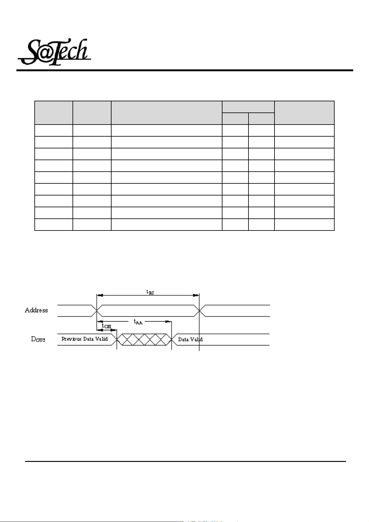
AC ELECTRICAL CHARACTERISTICS ( 0℃~70℃;Vcc=5V )
< READ CYCLE >
Name
Symbol Description
t
t
AVA X
t
t
AV QV
t
t
ELQV
t
t
GLQV
t
t
ELQX
t
t
GLQX
t
t
EHQZ
t
t
GHQZ
t
t
AXOX
RC
AA
ACE
OE
CLZ
OLZ
CHZ
OHZ
OH
Read Cycle Time 70
Address Access Time 70
Chip Select Access Time 70
Output Enable to Output Valid 40
(5)
Chip Select to Output Low Z 10
(5)
Output Enable to Output in Low Z 5
(5)
Chip Deselect to Output in High Z 0 35
(5)
Output Disable to Output in High Z 0 30
Address Change to Out Disable 10
SWITCHING WAVEFORMS (READ CYCLE)
READ CYCLE 1
[1,2,4]
-70 JEDEC
Unit
MIN MAX
ns
ns
ns
ns
ns
ns
ns
ns
ns
Rev. 1.0
MCU reserves the right to change product or specification without notice.
9
Page 10
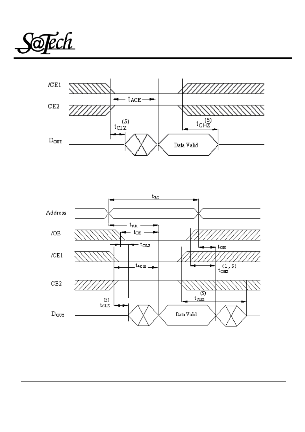
READ CYCLE 2
[1,3,4]
High Speed Super Low Power SRAM
8K-Word By 8 Bit HM6264
READ CYCLE 3
[1,4]
Rev. 1.0
MCU reserves the right to change product or specification without notice.
10
Page 11
NOTES:
1. /WE is high in read Cycle.
High Speed Super Low Power SRAM
8K-Word By 8 Bit HM6264
2. Device is continuously selected when /CE1 = V
and CE2=V
IL
IH.
3. Address valid prior to or coincident with /CE1 transition low and /or CE2 transition high.
4. /OE = V
5. Transition is measured ±500mV from steady state with C
guaranteed but not 100% tested.
.
IL
= 5pF as shown in Figure 1B. The parameter is
L
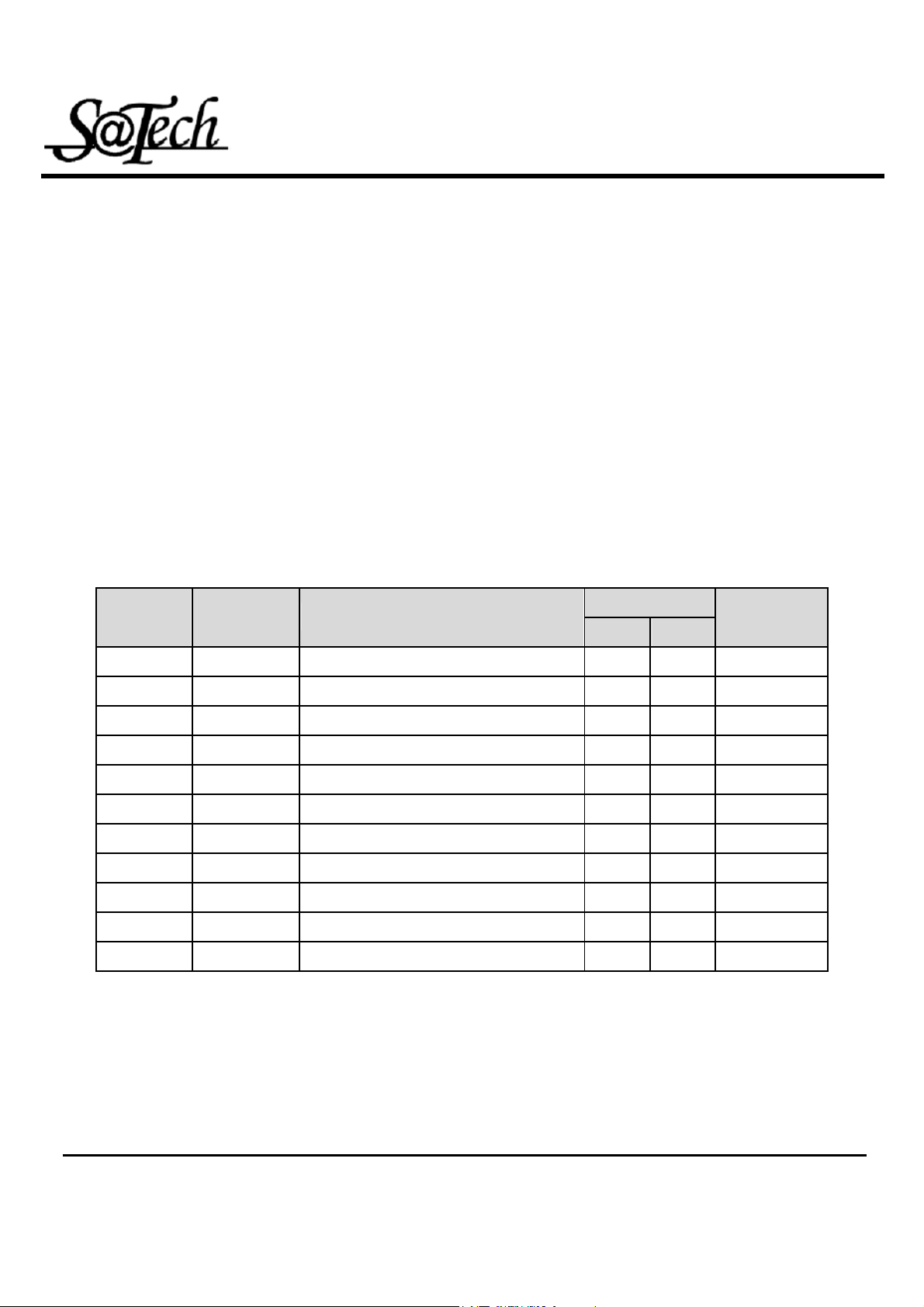
AC ELECTRICAL CHARACTERISTICS ( 0℃~70℃;Vcc=5V )
< WRITE CYCLE >
-70 JEDEC
MIN MAX
Name
t
t
AVA X
t
t
t
t
E1LWH
t
t
AV WL
t
t
AV WH
t
WLWH
t
t
WHAX
t
t
WLQZ
t
t
DVWH
t
t
WHDX
t
t
GHQZ
t
WHOX
Symbol Description
Write Cycle Time 70
WC
Chip Select to End of Write 70
CW
Address Setup Time 0
AS
Address Valid to End of Write 70
AW
Write Pulse Width 50
WP
Write Recovery Time 0
WR
WHZ
DW
OHZ
OW
(10)
DH
(10)
(10)
Write to Output in High Z 35
Data to Write Time Overlap 40
Data Hold for Write End 0
Output Disable to Output in High Z 0 30
End of Write to Output Active 5
Unit
ns
ns
ns
ns
ns
ns
ns
ns
ns
ns
ns
Rev. 1.0
MCU reserves the right to change product or specification without notice.
11
Page 12
High Speed Super Low Power SRAM
8K-Word By 8 Bit HM6264
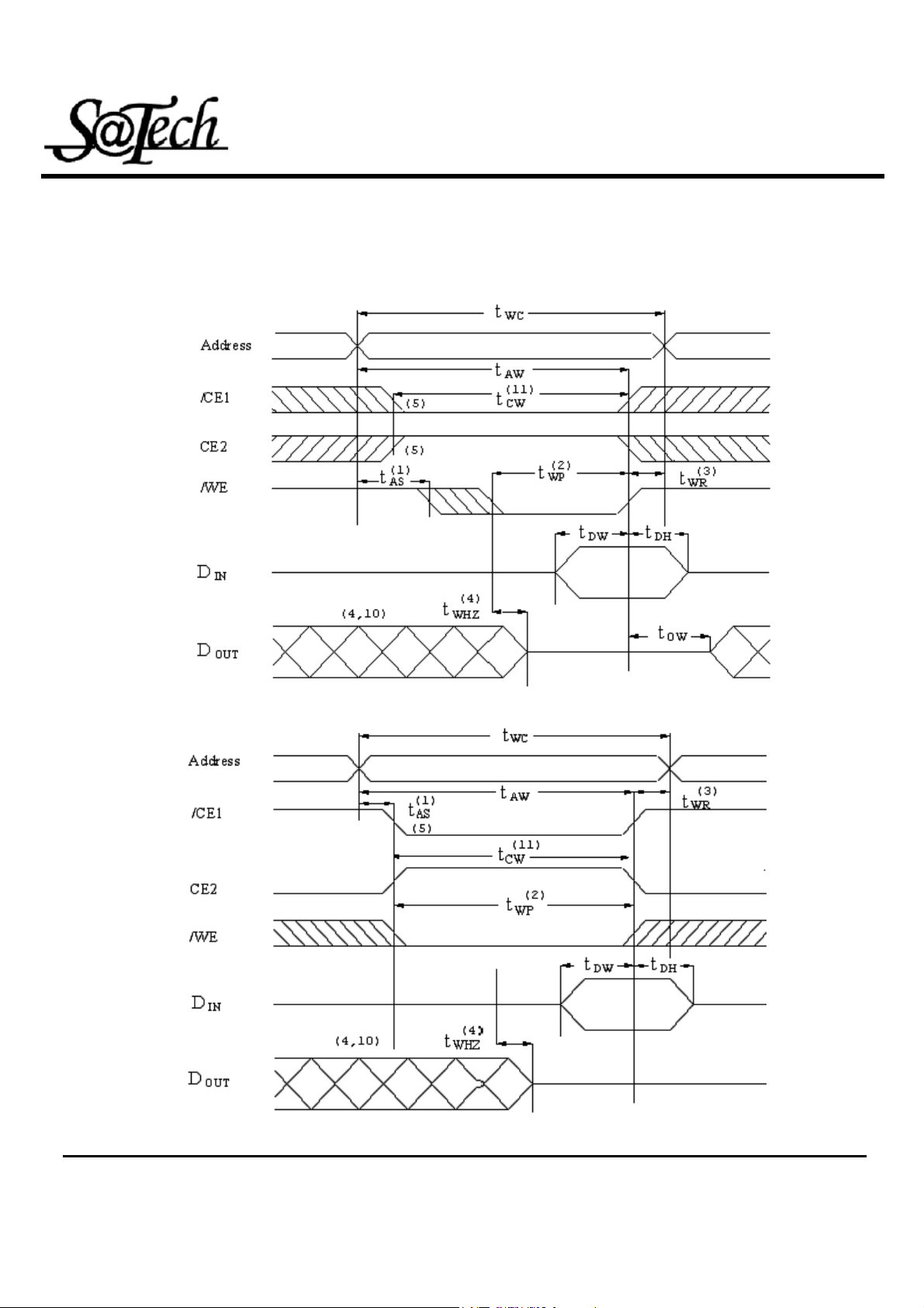
SWITCHING WAVEFORMS (WRITE CYCLE)
WRITE CYCLE1 (Write Enable Controlled)
WRITE CYCLE2 (Chip Enable Controlled)
Rev. 1.0
MCU reserves the right to change product or specification without notice.
12
Page 13
High Speed Super Low Power SRAM
8K-Word By 8 Bit HM6264
NOTES:
1. TAS is measured from the address valid to the beginning of write.
2. The internal write time of the memory is defined by the overlap of /CE1 and CE2 active and /WE
low. All signals must be active to initiate a write and any one signal can terminate a write by going
inactive. The data input setup and hold timing should be referenced to the second transition edge
of the signal that terminates the write.
3. TWR is measured from the earlier of /CE1 or /WE going high or CE2 going low at the end of write
cycle.
4. During this period, DQ pins are in the output state so that the input signals of opposite phase to
the outputs must not be applied.
5. If the /CE1 low transition or CE2 high transition occurs simultaneously with the /WE low
transitions or after the /WE transition, output remain in a high impedance state.
6. /OE is continuously low (/OE = VIL ).
7. D
8. D
is the same phase of write data of this write cycle.
OUT
is the read data of next address.
OUT
9. If /CE1 is low and CE2 is high during this period, DQ pins are in the output state. Then the data
input signals of opposite phase to the outputs must not be applied to them.
10. Transition is measured ±500mV from steady state with CL = 5pF as shown in Figure 1B. The
parameter is guaranteed but not 100% tested.
11. TCW is measured from the later of /CE1 going low or CE2 going high to the end of write.
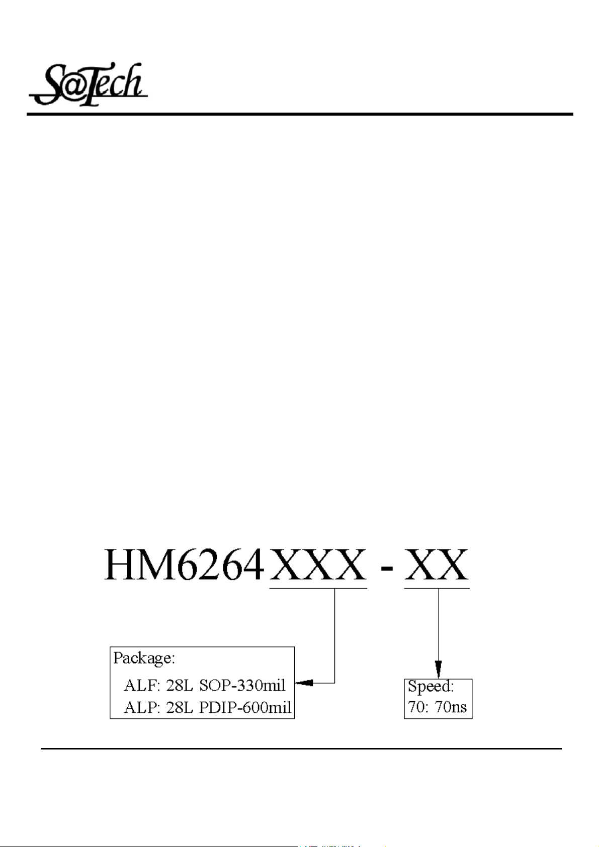
ORDER INFORMATION
Rev. 1.0
MCU reserves the right to change product or specification without notice.
13
Page 14
High Speed Super Low Power SRAM
8K-Word By 8 Bit HM6264
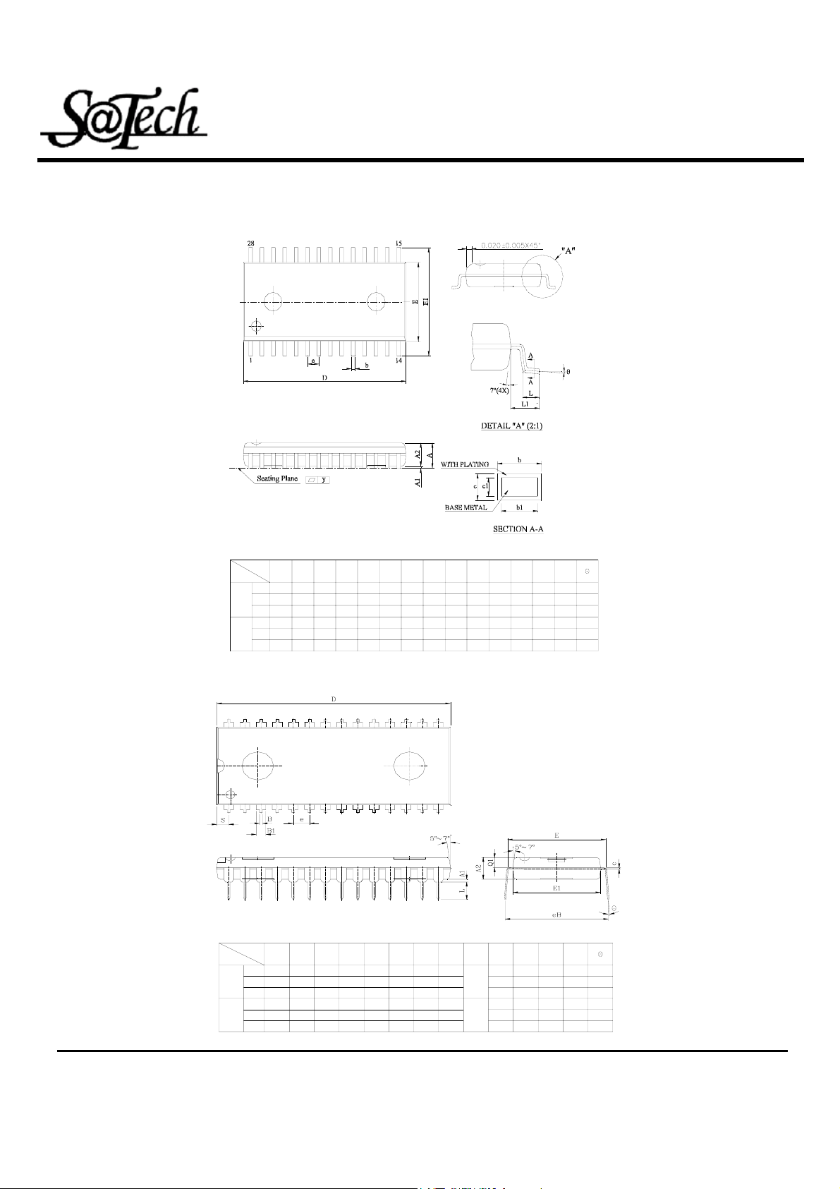
PACKAGE DIMENSIONS
28 pin SOP (330 mil) :
UNIT
28 pin PDIP (600mil):
SYMBOL
UNIT
mm
inch
SYMBOL
mm
inch
Min.
Nom.
Max.
Min.
Nom.
Max.
Min.
Nom.
Max.
Min.
Nom.
Max.
2.540
2.692
2.844
0.100
0.106
0.112
A1
0.254
_
_
0.010
_
_
A
0.102
0.226
0.350
0.004
0.009
0.014
A2
3.683
3.810
3.937
0.145
0.150
A1 A2 b b1
0.35
2.362
_
2.489
2.616
0.50
0.093
0.014
_
0.098
0.103
0.020
B
B1
1.270
0.330
1.524
0.457
1.778
0.584
0.050
0.013
0.060
0.018
0.070
0.0230.155
0.35
0.45
0.014
0.018
_
_
0.152
0.254
0.356
0.006
0.010
c
0.20
0.32
0.008
0.012
c
_
_
36.957
37.084
37.211
1.455
1.460
1.4650.014
c1 D E
0.20
_
0.28
0.008
_
0.011
E
D
14.986
15.240
15.494
0.590
0.600
17.983
18.110
18.237
0.708
0.713
0.718
8.280
8.407
8.534
0.326
0.331
0.336
E1
13.716
13.818
13.920
0.540
0.544
0.5480.610
11.506
11.811
12.116
0.453
0.465
0.477
2.540
(TYP)
0.100
(TYP)
e
1.118
1.270
1.422
0.044
0.050
0.056
15.748
16.256
16.764
0.620
0.640
L
0.700
0.964
1.228
0.0276
0.0380
0.0484
3.048
3.302
3.556
0.120
0.130
0.1400.660
E1
e
y
L1
_
1.778
2.032
2.286
0.070
0.080
0.090
0°
_
_
0.1
10°
_
0°
_
_
0.004
10°
Q1
S
1.651
3°
1.778
6°
1.905
9°
0.065
3°
0.070
6°
9°0.075
1.520
1.720
1.920
0.0598
0.0677
0.0756
LeB
Rev. 1.0
14
MCU reserves the right to change product or specification without notice.
 Loading...