

Page 1

System 6000
Electropneumatic Converters for Direct Current Signals
i/p Converter Type 6111
Application
Instruments used to convert direct current input signals into
pneumatic output signals for measuring and control tasks.
Especially suitable as intermediate element between electric
measuring devices and pneumatic controllers (or between
electric control devices and pneumatic control valves).
These converters are designed for use in all kinds of industrial
applications, especially in the field of process engineering.
The converters accept a load-independent 4 to 20 mA or 0 to
20 mA direct current input signal which they convert into a
pneumatic output signal.
Wide output pressure ranges can be selected for the Type 6111
i/p Converter by installing various converter modules (see Tech
nical data). The maximum output pressure that can be achieved
is 8 bar.
-
Special features
• Wide selection of measuring ranges
• High output pressures up to 8 bar
• Easy replacement of i/p module
• Zero reset at specific mA-value when switch-off electronic
function is activated (function can be activated as required)
• Operation possible without an upstream pressure regulator
• Version designed as rail-mounting unit with plastic housing
or as field unit for offshore applications in a stainless steel
enclosure
•
Supply air manifold for rail-mounting units available as
accessories for 3, 4, 5 and 6 converter units (Fig. 4)
Versions
•
Type 6111 designed as rail-mounting unit (Fig. 1) · Suitable
for snap-on mounting on a top-hat rail
•
Type 6111 designed as field unit for offshore applications
(Fig. 2) · Mounted using a bracket
Special versions (on request)
•
Input signal 0 (2) to 10 V with Type 6151 Module
•
Electric connection with an angle connector according to
DIN EN 175301-803 A
•
AS-Interface connection over Type 6150 Module
Fig. 1 · Type 6111 as rail-mounting unit
Fig. 2 · Type 6111 as field unit for offshore applications
Edition May 2007
Data Sheet T 6111 EN
Page 2

Principle of operation (Fig. 3)
Electropneumatic converters essentially consist of an i/p con
verter module operating according to the force-balance princi
ple and a connected volume booster.
When operated, the supplied direct current (4) flows through
the plunger coil (2) in the field of the permanent magnet (3). At
the balance beam (1), theforce of theplunger coil, whichis pro
portional to the current, is balanced against the force of the
back-pressure. The back-pressure is produced on the flapper
plate (6) by the air jet leaving the nozzle (7).
The nozzle is supplied with air from the pneumatic output (36).
At an input signal of0 mA, an output pressureof approximately
50 to 80 mbar already exists due to the offset spring.
The supply air (9) flowsin the lower diaphragm chamber, and a
certain amount flows to the output. When the current increases,
the flapper moves closer to the nozzle. The force of the resulting
back-pressure pushes both the diaphragm (5) and sleeve (8)
downwards, allowing additional air to enter the chamber. The
passing air volume increases until the forces on the diaphragm
obtain a state of equilibrium. When the current decreases, this
action isreversed. The back-pressure created by the nozzleand
flapper decreases, and the diaphragm is pressed upwards. In
this process, it releases the sleeve, if applicable, and opens the
vent (11) untilthe forces onthe diaphragm arebalanced again.
Devices with an input signal range from 4 to 20 mA have a
slide switch which activates the switch-off electronic function.
This function causes the pneumatic output to be vented up to
approx. 100 mbar when the input signal falls below 4.08 mA ±
tolerance. In this way, the tight shut-off function of a valve can
be guaranteed.
-
-
-
1 Balance beam
2 Plunger coil
3 Permanent magnet
4 Input
5 Diaphragm
6 Flapper plate
Fig. 3 · Functional diagram
7 Nozzle
8 Sleeve
9 Supply air
11 Vent
36 Output
Fig. 4 · Supply air manifold for Type 6111
2
T 6111 EN
Page 3
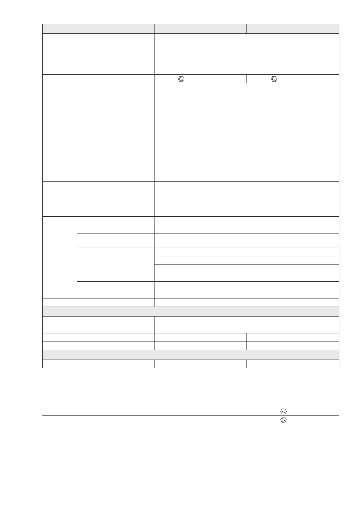
Technical data
Converter Type 6111 Rail-mounting unit Field unit
Input 4 to 20 mA (0 to 20 mA on request);
Load Standard
Explosion-protected version
Device without switch-off electronics
Explosion protection II 2 G EEx ia IIC T6 II 3 G EEx nA II T6
Output
With Type 6112 i/p Module
Special ranges adjustable at the factory to meet customer specifications:
Module A
Module B
Module C
Module D
Module E
Module F
Module G
Module H
Maximum air output capacity
Supply air At least 0.4 bar above the upper signal pressure value,
Air consumption
Performance
2)
Hysteresis
Deviation from terminal-based
conformity
Influence in % of the final value
Alternating load, supply air failure, interruption of input current: < 0.3 %
Ambient temperature: Lower range value < 0.03 %/°C, measuring span < 0.03 %/°C
Dynamic performance With an output between 0.2 and 1 bar
Limiting frequency 5.3 Hz
Phase shift –130°
Variable position Maximum 3.5 % depending on how device is mounted, e.g.±1 % in horizontal position
Ambient conditions, degree of protection, weight
Ambient temperature –20 to 70 °C
Storage temperature –40 to 70 °C
Degree of protection IP 20 IP 65
Weight approx. 0.35 kg 1.9 kg
Materials
Housing Glass fiber reinforced polyamide Stainless steel 1.4581
1)
The maximum possible output pressure is 8 bar
2)
Measured according to IEC 770
For split-range: 4 to 12 mA or 12 to 20 mA;
Other signals on request
6 V (corresponding to 300Ωat 20 mA)
≤
7 V (corresponding to 350Ωat 20 mA)
4 V (corresponding to 200Ωat 20 mA)
≤
0.2 to 1 bar (3 to 15 psi) (standard range)
0.4 to 2 bar (6 to 30 psi) (standard range)
Initial value; SpanΔp
0.1 to 0.4 bar; 0.75 to 1.0 bar
0.1 to 0.4 bar; 1.0 to 1.35 bar
0.1 to 0.4 bar; 1.35 to 1.81 bar
0.1 to 0.8 bar; 1.81 to 2.44 bar
0.1 to 0.8 bar; 2.44 to 3.28 bar
0.1 to 0.8 bar; 3.28 to 4.42 bar
0.1 to 1.2 bar; 4.42 to 5.94 bar;
0.1 to 1.2 bar; 5.94 to 8.0 bar
3
/h at an output of 0.6 bar (0.2 to 1.0 bar)
2.0 m
3
2.5 m
/h at an output of 1.2 bar (0.4 to 2.0 bar)
3
8.5 m
/h at an output of 5.0 bar (0.1 to 8.0 bar)
1)
maximum 10 bar without upstream pressure regulator
3
0.08 m
0.10 m
Maximum 0.26 m
/h at 1.4 bar
n
3
/h at 2.4 bar
n
3
/h at 10 bar
n
Characteristic: Output linear to the input
0.3 % of the final value
≤
1 % of the final value
≤
Supply air: 0.1 %/0.1 bar
List of issued explosion protection certificates
Type of approval Certificate number Date Comments
Type 6111-1: EC Type Examination Certificate
Type 6111-8: Statement of Conformity
PTB 01 ATEX 2174 2001-11-26 II 2 G EEx ia IIC T6
PTB 02 ATEX 2013 X 2001-11-26 II 3 G EEx nA II T6
The certificates are contained in the mounting and operating instructions or can be requested.
3 T 6111 EN
Page 4

Electrical connection Installation
Rail-mounting unit for mounting on a top hat rail acc. to
•
DIN EN 50022, 35 mm wide
Wall mounting possible, using holes with Ø 5.5 mm
–
Air connections (supply air and output):
–
hose connection suitable for hose4x1(outer∅6 mm) as
standard; also available as ports with
female thread
Electrical connections:
–
Terminals for 0.5 to 2.5 mm² wires
Note: On using a plug-on terminal, the connections
marked “+“ and “–“ at the front of the converter are to be
ignored.
Field unit for offshore applications mounted using a
•
bracket
Bracket (stainless steel), order no: 1400-7432
–
Pneumatic connections: ¼ NPT
–
Electrical connection: M20 x 1.5
–
1
NPT, G
8
1
8
or M5
4
T 6111 EN
Page 5

Article code
Converter Type 6111-xxxxxxxxxxxxxxxx
Explosion
protection
Without
II 2G EEx ia IIC T6 (ATEX)
II 3G EEx nA II T6 (ATEX)
Housing For rail mounting, 35 mm top-hat rail (DIN EN 50022)
Field unit made of stainless steel 1.4581
i/p module Type 6109
Type 6112
Input 4 to 20 mA with switch-off electronic function
0 to 20 mA without switch-off electronic function
1)
4 to 12 mA with switch-off electronic function
12 to 20 mA with switch-off electronic function
Booster I (output above 0.1 bar/3 psi)
II (output above 0 bar/0 psi)
2)
Output 0.2 to 1.0 bar
3 to 15 psi
0.4 to 2.0 bar
6 to 30 psi
Special ranges
3)
Initial value
0.1 to 0.4 bar
0.1 to 0.4 bar
0.1 to 0.4 bar
0.1 to 0.8 bar
0.1 to 0.8 bar
0.1 to 0.8 bar
0.1 to 1.2 bar
0.1 to 1.2 bar
SpanΔp
0.75 to 1.00 bar
1.00 to 1.35 bar
1.35 to 1.81 bar
1.81 to 2.44 bar
2.44 to 3.28 bar
3.28 to 4.42 bar
4.42 to 5.94 bar
5.94 to 8.00 bar
0
180
1
0
1
1
2
0
1
2
0
2
2
0
3
2
0
4
1
2
2
2
2
2
2
2
2
2
2
2
2
1
0
1
1
0
2
1
0
3
1
0
4
1
1
1
2
1
3
1
4
1
5
1
6
1
7
1
8
Direction of action Increasing/increasing
Increasing/decreasing
Pneumatic
connection
Hose connection M10 x 1 for hose 4 x 1
1
-27 NPT female thread
8
ISO-228/1-G
1
female thread
8
M5 female thread
¼-18 NPT
Electrical
connection
Terminals for 0.5 to 2.5 mm² wires
Angle connector acc. to DIN EN 175301-803
M20 x 1.5
Degree of
protection
IP 20
IP 65
2
0
0
0
0
1
0
0
1
0
1
1
2
0
1
2
3
4
1
2
3
1
2
Temperature range Tmin≥–20 °C 0
Special version Without 000
1)
Without switch-off electronic function and without potentiometer for zero and span adjustment
2)
A stable compressed air network is necessary for the version with booster II.
The specifications concerning supply air pressure need to be strictly observed (always exactly 0.4 bar greater than the max. output
signal).
3)
Specify setting range, e.g. set to 0.1 to 4 bar;
Output pressure max. 8 bar, supply air max. 10 bar
5 T 6111 EN
Page 6
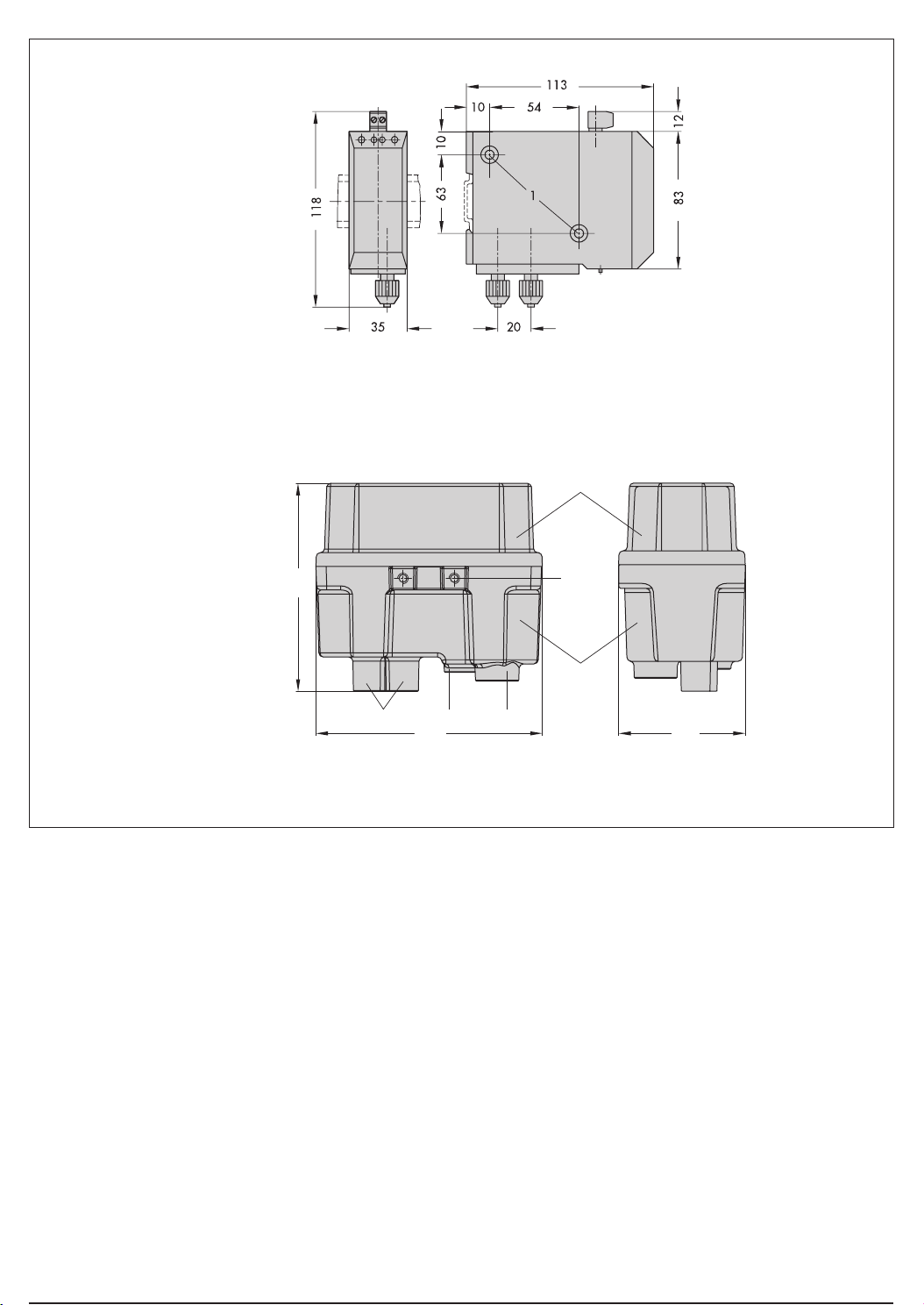
Dimensions in mm
Type 6111 designed as rail-mounting unit
1 Holes for wall mounting
Cover
126
NPT 1/4 R 1/4 M20x1.5
Type 6111 designed as field unit
M6x1
Enclosure
76136
Specifications subject to change without notice.
 Loading...