

Page 1
5B Series 16 Channel Backplane
FEATURES
Mix and Match 5B Series I/O Module Capability
Factory Mutual (FM) Approved
Approved for Use in Class I, Division2, Groups A, B, C, and D
Locations.
CE Certified: EMC Directive in Heavy Industrial Applications
1500 V rms Channel/Channel and Input/Output Isolation
16- channels
o
C to +85oC Temperature Range
-25
Single Threaded Insert for Module Hold Down
APPLICATIONS
Industrial Signal Conditioning
Industrial Signal Isolation
Industrial Signal Filtering
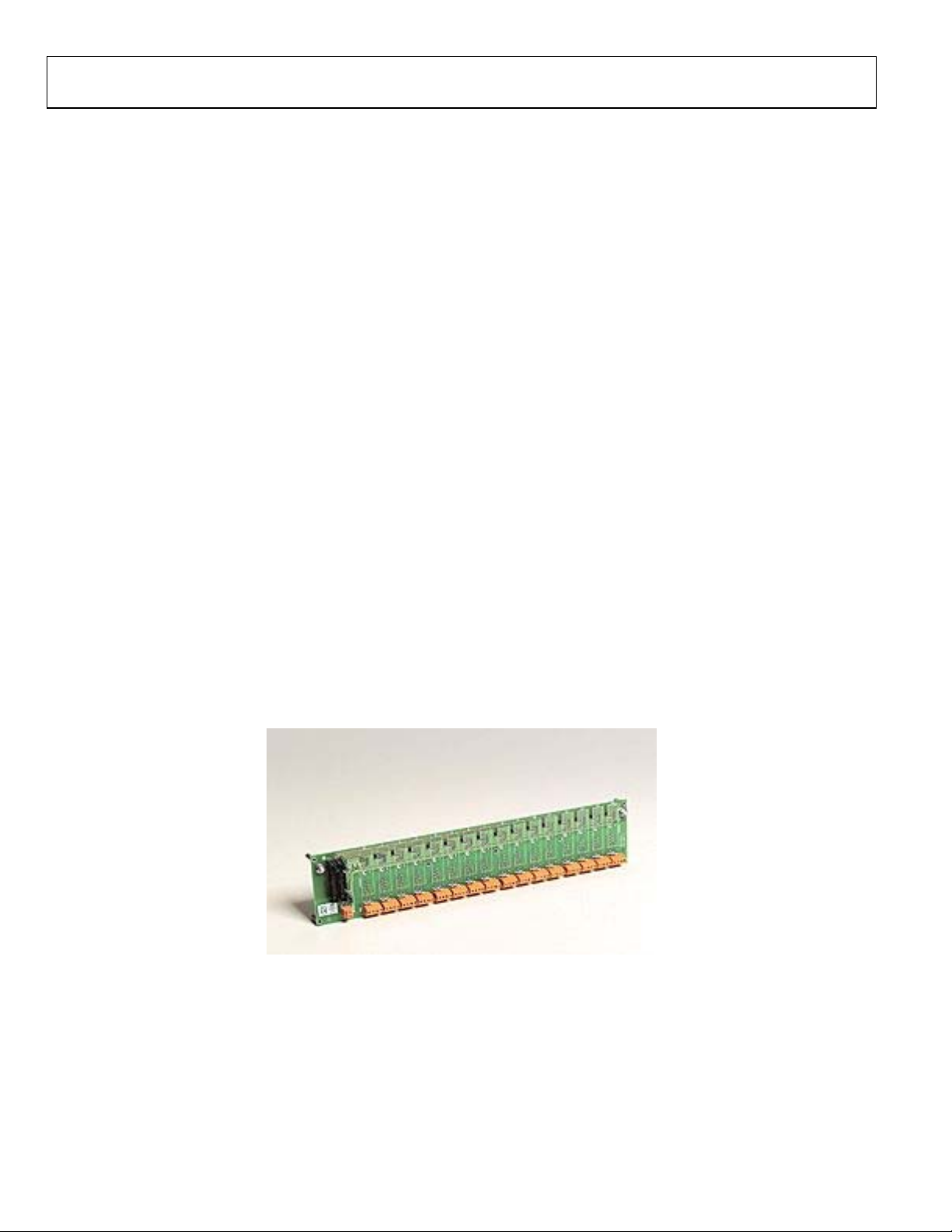
PRODUCT OVERVIEW
To address diverse applications, the 5B Series includes a family
of backplanes and mounting cards which provide a complete
signal conditioning solution. The 16-channel backplane can be
mounted in a 19” x 3.5” panel space, providing an economical
means to handle signals.
5B01
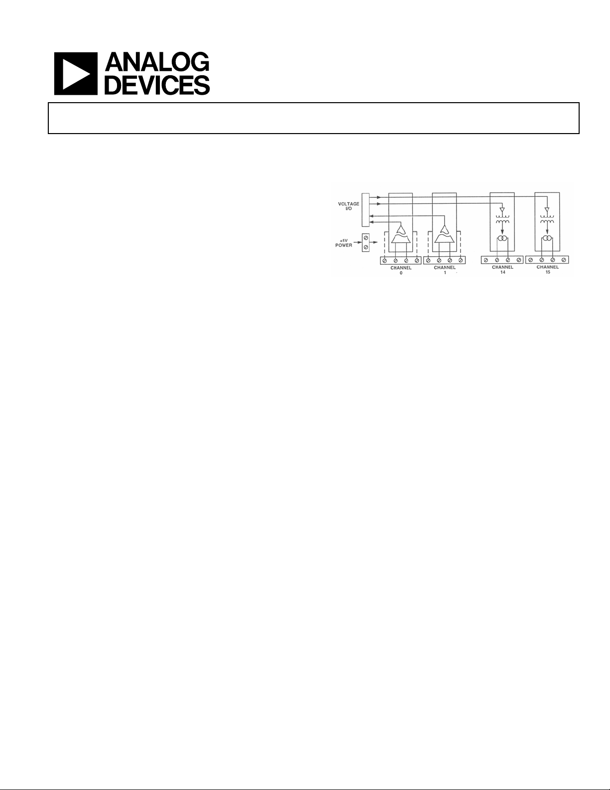
FUNCTIONAL BLOCK DIAGRAM
Figure 1 5B01 Functional Block Diagram
This backplane provides four screw terminals per channel for
all field connections. These connections satisfy all transducer
inputs, process current outputs and provide transducer
excitation when necessary. A cold junction temperature sensor
(model AC1361) sensor is also supplied on each channel to
accommodate thermocouple input modules. A pair of pin
sockets permits installation of the AC1362 current sensing
resistor used with the 5B32 current input module on the 16channel backplane, a 26-pin system interface connector
provides high level I/O for all channels. The 5B01 Series
backplane requires a regulated +5VDC external power source.
Rev. 0
Information furnished by Analog Devices is believed to be accurate and reliable.
However, no responsibility is assumed by Analog Devices for its use, nor for any
infringements of patents or other rights of third parties that may result from its use.
Specifications subject to change without notice. No license is granted by implication
or otherwise under any patent or patent rights of Analog Devices. Trademarks and
registered trademarks are the property of their respective companies.
One Technology Way, P.O. Box 9106, Norwood, MA 02062-9106, U.S.A.
Tel: 781.329.4700
Fax: 781.326.8703 © 2005 Analog Devices, Inc. All rights reserved.
www.analog.com
Page 2
GENERAL DESCRIPTION
Model 5B01 Backplane - The 5B01 diagrammed in Figure 1, is
a 16 channel backplane that provides single-ended, high level
analog input/output pins on the system connector. It is pin
compatible with Analog Devices’ 3B Series applications. (Note,
however, that 5B Series modules provide a +5V output swing
rather than the +10V swing provided by 3B Series modules.)
Model 5B01 System Connectors – Signal connections between
the 5B01 backplane and the associated measurement and
control system are made at P1 and P2. These connectors are
identical electrically. The redundant connectors may be useful if
a 5B01 is used for both analog input and analog output and the
data acquisition system has separate input and output
connectors. A signal path is provided for each channel and, in
addition, a number of grounding pins are present in the
connector pin-out to provide inter-channel shield conductors in
the ribbon cable. In some cases, discussed below, the ground
conductors will not provide an accurate signal reference, so a
SENSE pin is also provided in the pin-out. Several jumper and
component options on the backplane provide optimum ground
connections for various circumstances.
Model 5B01 Grounding – Each 5B01 backplane is factory
configured with Jumpers W1, W3, and W4 installed. Jumper
W1 grounds the shield wires in the ribbon cable (Pins 3, 6, 12,
15, 18, 21, and 24) at the 5B01 backplane. This will usually be
the primary ground connection between the 5B01 and the
5B01
measurement system. This connection is required if output
modules will be used on the backplane. It is also required is
there is no high impedance sense input (input Low of a
differential or pseudo-differential system) available on the
measurement system. Jumper W3 connects the sense input, if
available, to Pin 25 so that the 5B01’s ground is read. It can be
left in place at all times. Jumper W4 connects +5VDC power
common to input/output common (backplane measurement
ground). A connection between power common and
input/output common is important for the 5B Series modules to
function properly, however, if this connection is made elsewhere
in your system the best place is usually near the A/D or D/A
converters), W4 should be cut, since a ground loop could result.
Model 5B01 Inter-channel Bridge Jumpers – The 5B01 gives
the user the capability of directing the voltage output of any
input module to an adjacent output module (e.g., Model 5B39)
simply by placing a jumper between the pins of the two
modules (input to channel n, output from channel n+1). This
feature can be used to provide an isolated current output from
an isolated input module, giving two levels of 1500 V rms
isolation. Model AC1344 provides ten jumpers.
.
Figure 2
Rev. 0 | Page 2 of 7
Page 3

5B01
5B01 Specifications
(typical @ +25°C and Vs =+5 V dc Power)
Description Model 5B01
Number of Channels
ISOLATION
Input-to-Output Continuous
Channel-to-Channel Continuous
MECHANICAL DIMENSIONS – with modules
WEIGHT
MOUNTING STANDOFFS
COLD JUNCTION TEMPERATURE SENSORS
Number provided on backplane
Type
Initial Accuracy @ +25oC
Accuracy +5oC to +45oC
SYSTEM I/O CONNECTOR
Number
Type
POWER SUPPLY OPTIONS
Voltage; Operating
Voltage; Max Safe Limit – with modules
Current – without modules
Fuse; (F1)
Environmental
Temperature Range
Rated Performance -25°C to +85°C
Operating -40°C to +85°C
Storage -40°C to +85°C
Relative Humidity, 24 hours 0 to 95% @ +60°C noncondensing
16
1500 V rms, Maximum
1500 V rms, Maximum
3.5” x 17.4” x 3.2”
(88.9 mm x 442 mm x 81.3 mm)
11.25 oz. (305 g)
7
16
Model AC1361
+0.5oC
+0.5oC (+0.0125oC/oC)
2, 26-pin
Amp 746290-6
+5 VDC +5%
+6.0 VDC Max.
0
4 Ampere Littlefuse © Type 252 004
Rev. 0 | Page 3 of 7
Page 4

PIN CONFIGURATION AND FUNCTIONAL DESCRIPTION
Table 1. Pin Function Descriptions—
Pin No. Description
1 CHANNEL 0
2 CHANNEL 8
3 COMMON
4 CHANNEL 9
5 CHANNEL 1
6 COMMON
7 CHANNEL 2
8 CHANNEL 10
9 COMMON
10 CHANNEL 11
11 CHANNEL 3
12 COMMON
13 CHANNEL 4
14 CHANNEL 12
15 COMMON
16 CHANNEL 13
17 CHANNEL 5
18 COMMON
19 CHANNEL 6
Figure 3 5B01 Pin-outs
20 CHANNEL 14
21 COMMON
22 CHANNEL 15
23 CHANNEL 7
24 COMMON
25 SENSE 25
26 NO CONNECTION
5B01
ESD CAUTION
ESD (electrostatic discharge) sensitive device. Electrostatic charges as high as 4000 V readily accumulate on the human
body and test equipment and can discharge without detection. Although this product features proprietary ESD
protection circuitry, permanent damage may occur on devices subjected to high energy electrostatic discharges.
Therefore, proper ESD precautions are recommended to avoid performance degradation or loss of functionality.
Rev. 0 | Page 4 of 7
Page 5

OUTLINE DIMENSIONS
5B01
Figure 3 Outline Dimensions
Rev. 0 | Page 5 of 7
Page 6

NOTES
5B01
Rev. 0 | Page 6 of 7
Page 7

NOTES
5B01
© 2005 Analog Devices, Inc. All rights reserved. Trademarks and
registered trademarks are the property of their respective companies.
D05410-0-2/05(0)
Rev. 0 | Page 7 of 7
 Loading...