

Page 1
LM195/LM395
Ultra Reliable Power Transistors
General Description
The LM195/LM395 are fast, monolithic power transistors
with complete overload protection. These devices, which act
as high gain power transistors, have included on the chip,
current limiting, power limiting, and thermal overload protection making them virtually impossible to destroy from any
type ofoverload.In the standard TO-3transistor power package, the LM195 will deliver load currents in excess of 1.0A
and can switch 40V in 500 ns.
The inclusion of thermal limiting, a feature not easily available in discrete designs, provides virtually absolute protection against overload. Excessive power dissipation or inadequate heat sinking causes the thermal limiting circuitry to
turn off the device preventing excessive heating.
The LM195 offers a significant increase in reliability as well
as simplifying power circuitry. In some applications, where
protection is unusually difficult, such as switching regulators,
lamp or solenoid drivers where normal power dissipation is
low, the LM195 is especially advantageous.
The LM195 is easy to use and only a few precautions need
be observed. Excessive collector to emitter voltage can destroy the LM195 as with any power transistor. When the device is used as an emitter follower with low source imped-
ance, it is necessary to insert a 5.0k resistor in series with
the base lead to prevent possible emitter follower oscillations. Although the device is usually stable as an emitter follower,the resistor eliminates the possibility of trouble without
degrading performance. Finally, since it has good high frequency response, supply bypassing is recommended.
For low-power applications (under 100 mA), refer to the
LP395 Ultra Reliable Power Transistor.
The LM195/LM395 are available in standard TO-3 power
packages and solid Kovar TO-5. The LM195 is rated for operation from −55˚C to +150˚C and the LM395 from 0˚C to
+125˚C.
Features
n Internal thermal limiting
n Greater than 1.0A output current
n 3.0 µA typical base current
n 500 ns switching time
n 2.0V saturation
n Base can be driven up to 40V without damage
n Directly interfaces with CMOS or TTL
n 100%electrical burn-in
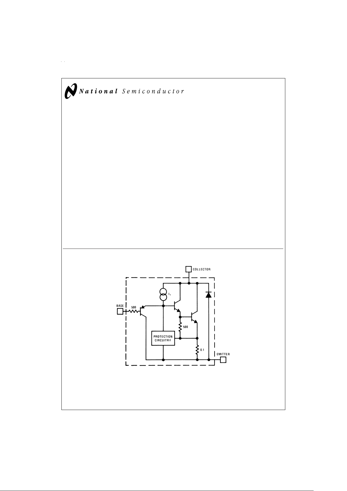
Simplified Circuit
DS006009-1
June 1999
LM195/LM395 Ultra Reliable Power Transistors
© 1999 National Semiconductor Corporation DS006009 www.national.com
Page 2
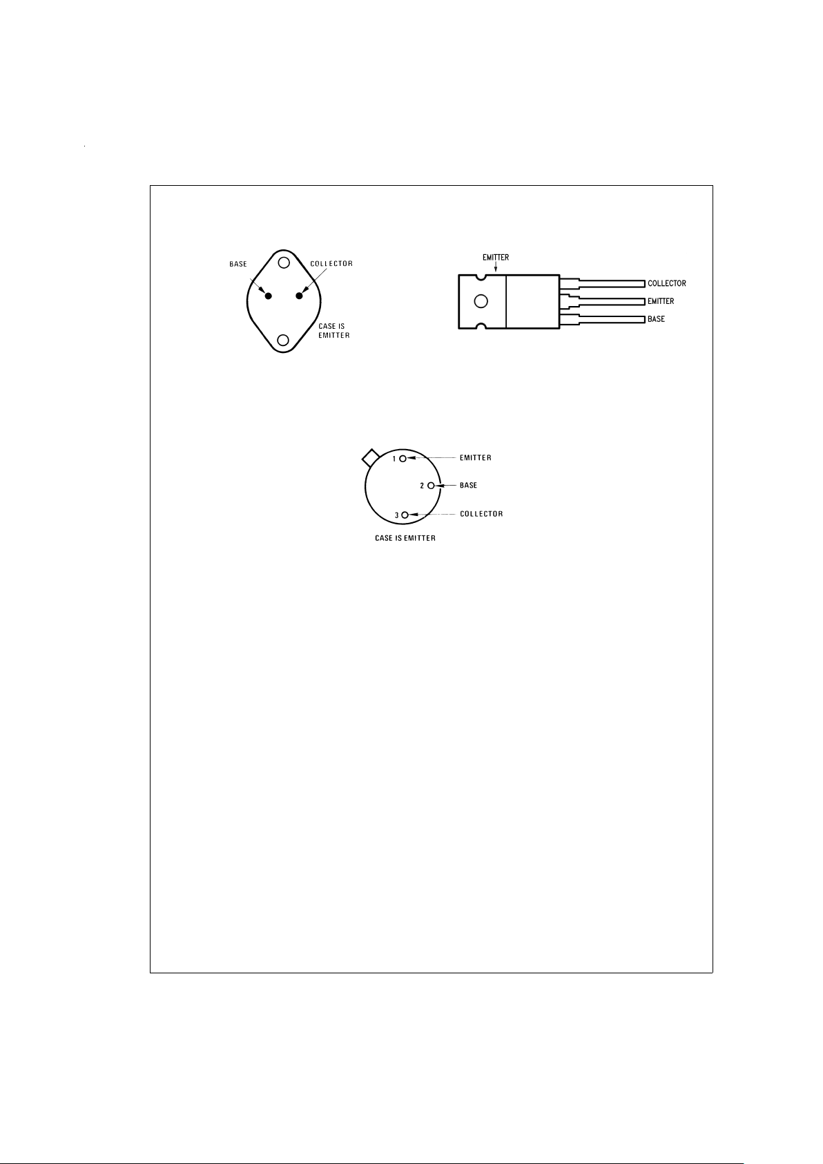
Connection Diagrams
TO-3 Metal Can Package
DS006009-2
Bottom View
Order Number LM195K/883
See NS Package Number K02A
TO-220 Plastic Package
DS006009-3
Case is Emitter
Top View
Order Number LM395T
See NS Package Number T03B
TO-5 Metal Can Package
DS006009-4
Bottom View
Order Number LM195H/883
See NS Package Number H03B
www.national.com 2
Page 3
Absolute Maximum Ratings (Note 1)
If Military/Aerospace specified devices are required,
please contact the National Semiconductor Sales Office/
Distributors for availability and specifications.
Collector to Emitter Voltage
LM195 42V
LM395 36V
Collector to Base Voltage
LM195 42V
LM395 36V
Base to Emitter Voltage (Forward)
LM195
LM395
42V
36V
Base to Emitter Voltage (Reverse) 20V
Collector Current Internally Limited
Power Dissipation Internally Limited
Operating Temperature Range
LM195 −55˚C to +150˚C
LM395 0˚C to +125˚C
Storage Temperature Range −65˚C to +150˚C
Lead Temperature
(Soldering, 10 sec.) 260˚C
Preconditioning
100%Burn-In In Thermal Limit
Electrical Characteristics
(Note 2)
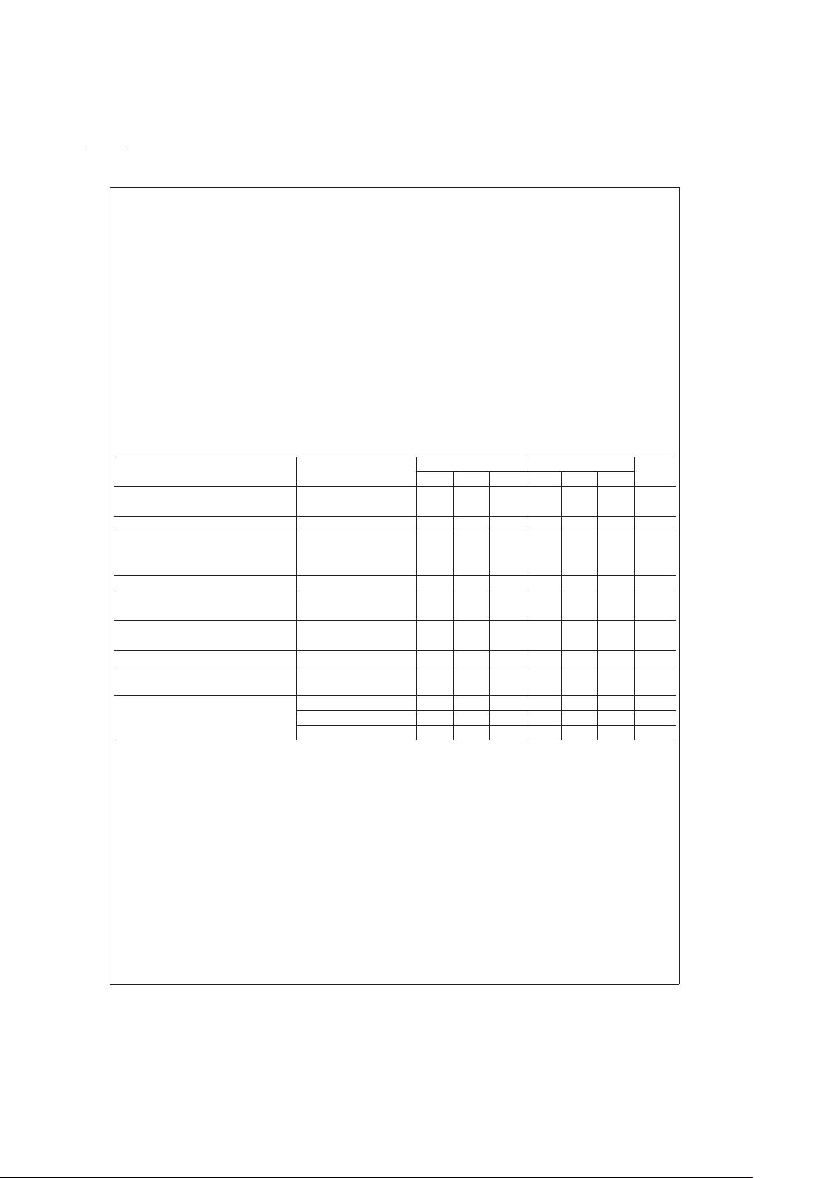
Parameter Conditions LM195 LM395 Units
Min Typ Max Min Typ Max
Collector-Emitter Operating Voltage I
Q
≤ IC≤ I
MAX
42 36 V
(Note 4)
Base to Emitter Breakdown Voltage 0 ≤ V
CE
≤ V
CEMAX
42 36 60 V
Collector Current
TO-3, TO-220 V
CE
≤ 15V 1.2 2.2 1.0 2.2 A
TO-5 V
CE
≤ 7.0V 1.2 1.8 1.0 1.8 A
Saturation Voltage I
C
≤ 1.0A, T
A
=
25˚C 1.8 2.0 1.8 2.2 V
Base Current 0 ≤ I
C
≤ I
MAX
3.0 5.0 3.0 10 µA
0 ≤ V
CE
≤ V
CEMAX
Quiescent Current (IQ)V
be
=
0
2.0 5.0 2.0 10 mA
0 ≤ V
CE
≤ V
CEMAX
Base to Emitter Voltage I
C
=
1.0A, T
A
=
+25˚C 0.9 0.9 V
Switching Time V
CE
=
36V, R
L
=
36Ω,
500 500 ns
T
A
=
25˚C
Thermal Resistance Junction to TO-3 Package (K) 2.3 3.0 2.3 3.0 ˚C/W
Case (Note 3) TO-5 Package (H) 12 15 12 15 ˚C/W
TO-220 Package (T) 4 6 ˚C/W
Note 1: “Absolute Maximum Ratings” indicate limits beyond which damage to the device may occur. Operating Ratings indicate conditions for which the device is
functional, but do not guarantee specific performance limits.
Note 2: Unless otherwise specified, these specifications apply for −55˚C ≤ T
j
≤ +150˚C for the LM195 and 0˚C ≤ +125˚C for the LM395.
Note 3: Without a heat sink, the thermal resistance of the TO-5 package is about +150˚C/W, while that of the TO-3 package is +35˚C/W.
Note 4: Selected devices with higher breakdown available.
Note 5: Refer to RETS195H and RETS195K drawings of military LM195H and LM195K versions for specifications.
www.national.com3
Page 4
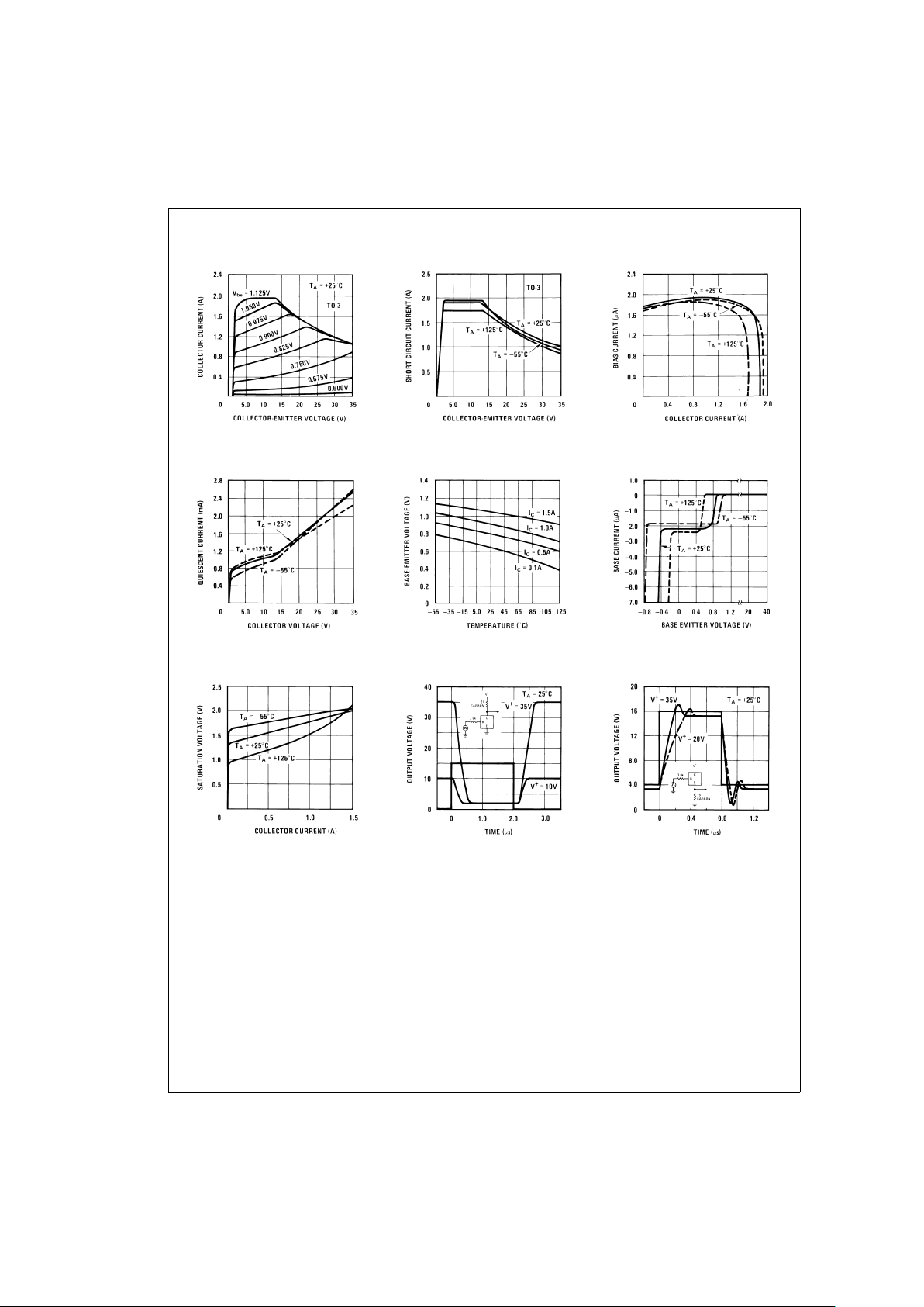
Typical Performance Characteristics (for K and T Packages)
Collector Characteristics
DS006009-33
Short Circuit Current
DS006009-34
Bias Current
DS006009-35
Quiescent Current
DS006009-36
Base Emitter Voltage
DS006009-37
Base Current
DS006009-38
Saturation Voltage
DS006009-39
Response Time
DS006009-40
Response Time
DS006009-41
www.national.com 4
Page 5
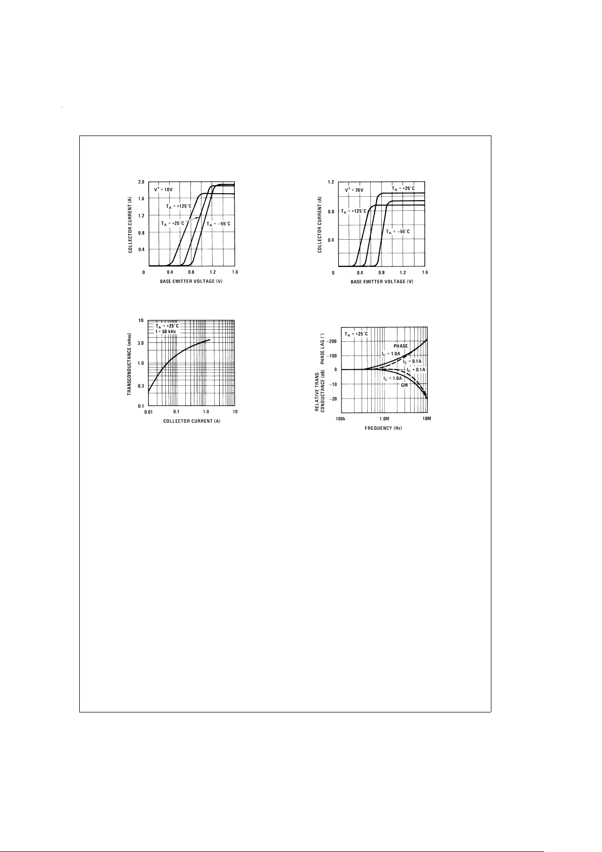
Typical Performance Characteristics (for K and T Packages) (Continued)
10V Transfer Function
DS006009-7
36V Transfer Function
DS006009-8
Transconductance
DS006009-9
Small Signal Frequency
Response
DS006009-10
www.national.com5
Page 6
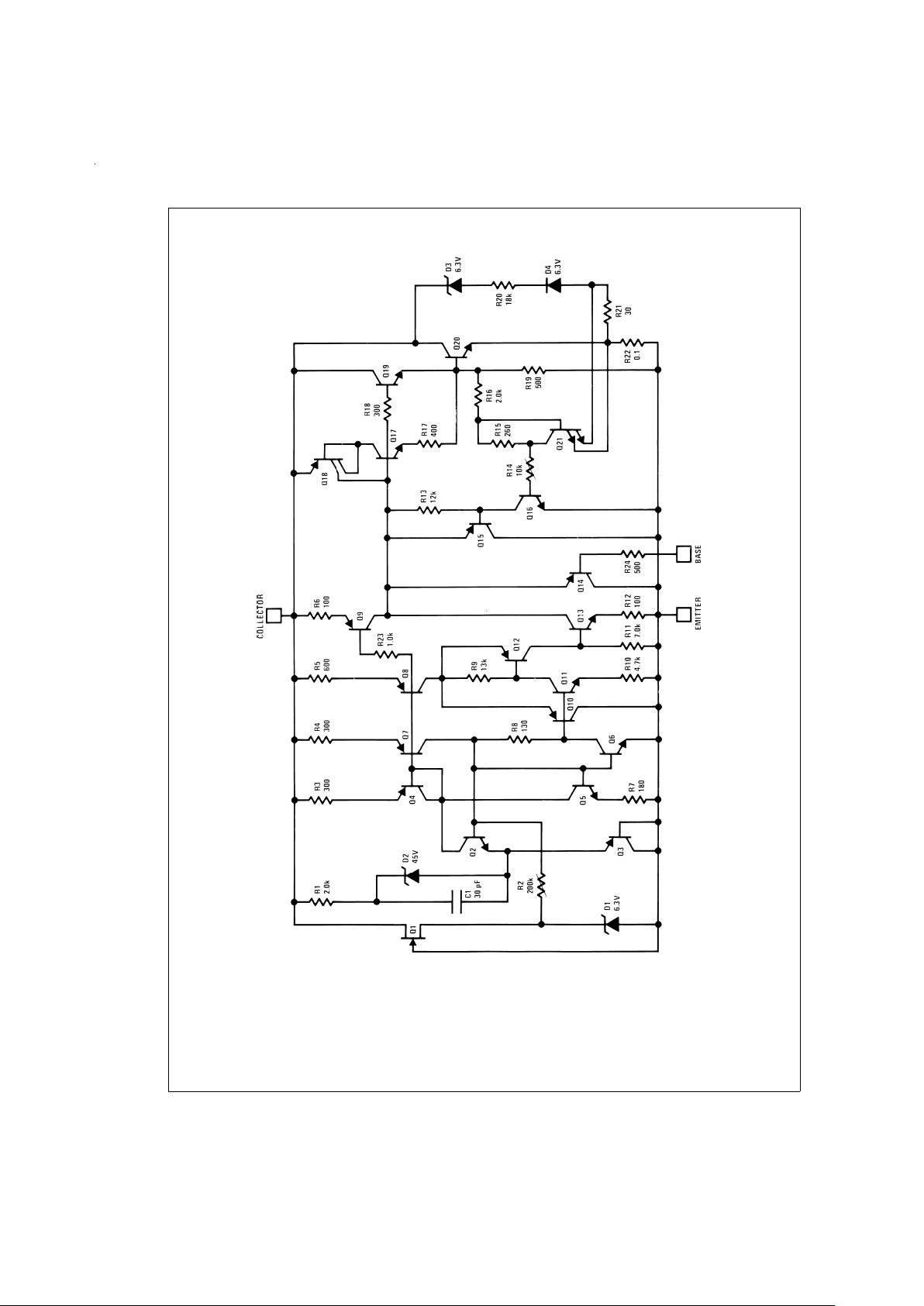
Schematic Diagram
DS006009-11
www.national.com 6
Page 7
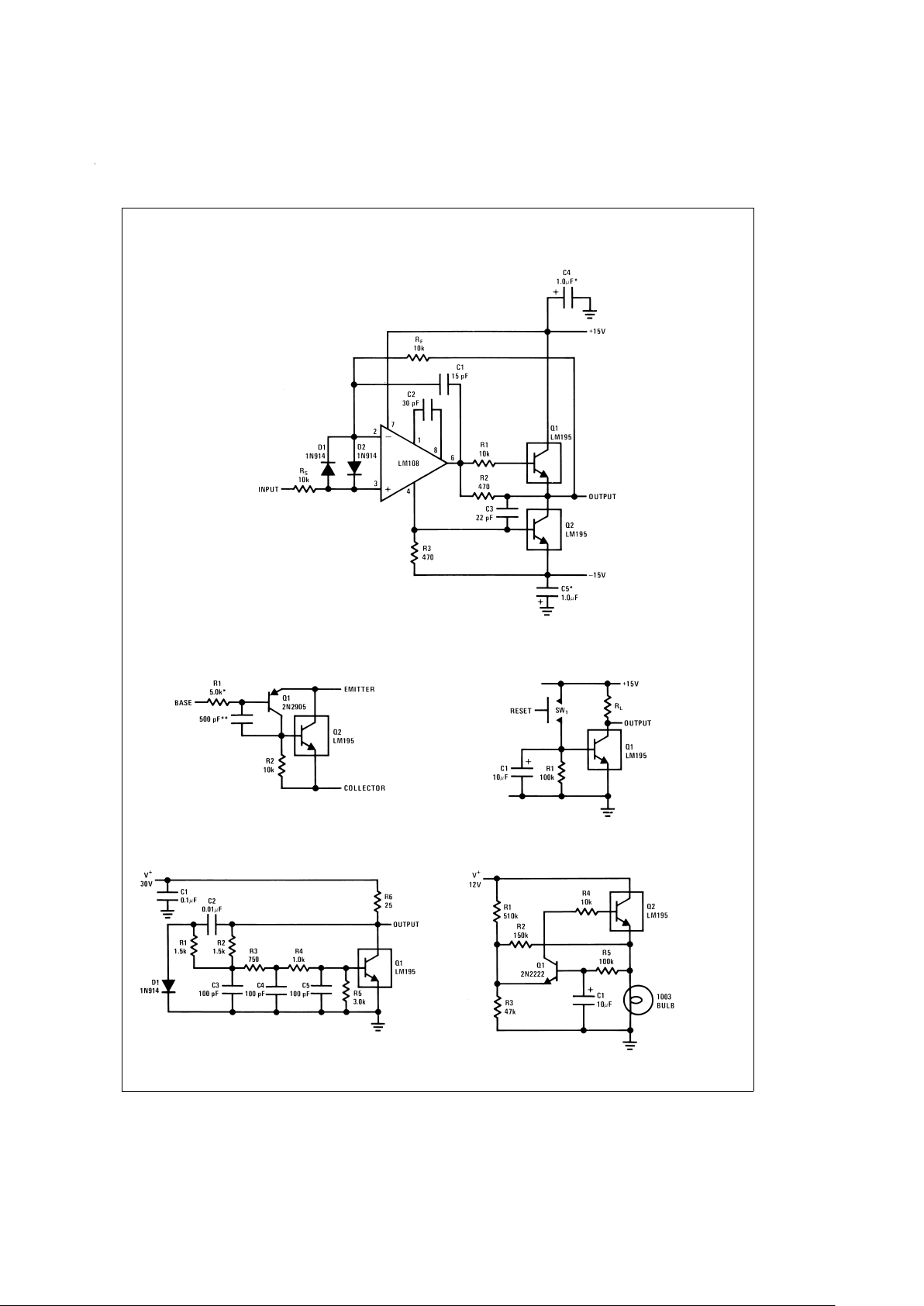
Typical Applications
1.0 Amp Voltage Follower
DS006009-12
*
Solid Tantalum
Power PNP
DS006009-13
*
Protects against excessive base drive
**
Needed for stability
Time Delay
DS006009-14
1.0 MHz Oscillator
DS006009-15
1.0 Amp Lamp Flasher
DS006009-16
www.national.com7
Page 8
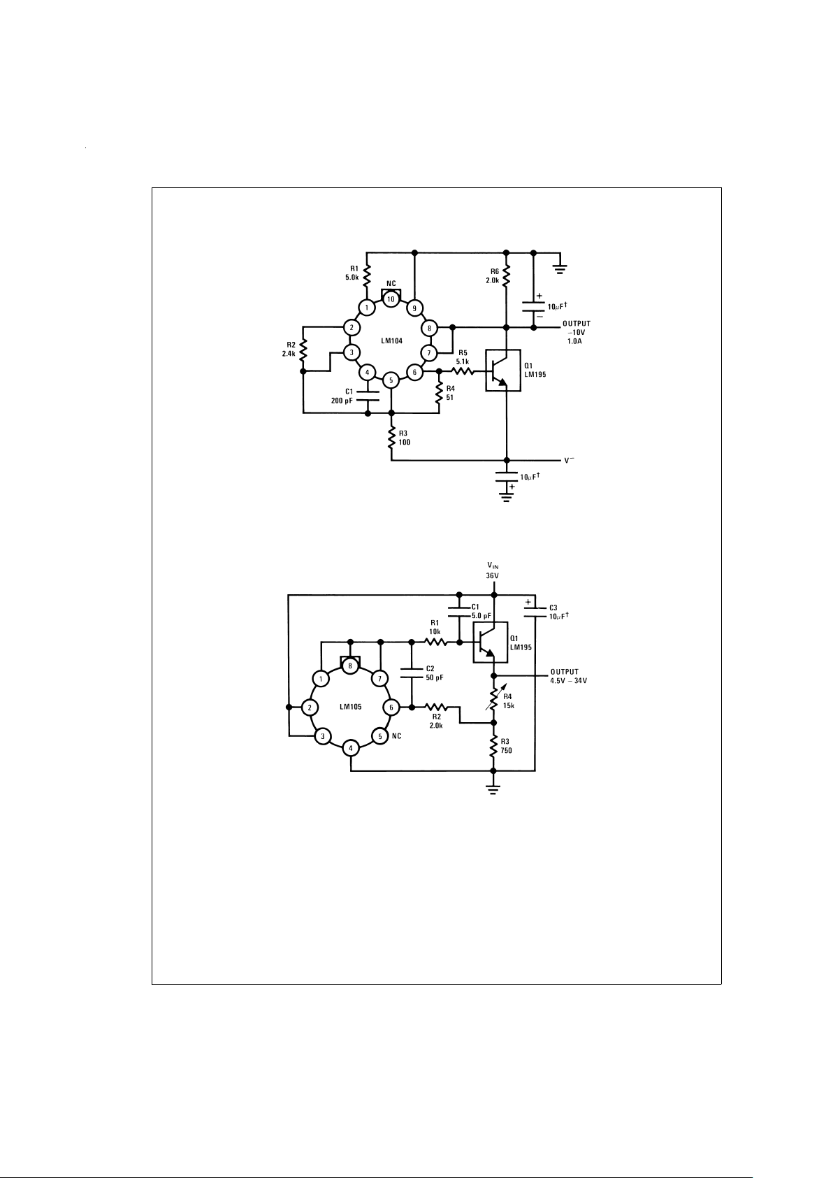
Typical Applications (Continued)
1.0 Amp Negative Regulator
DS006009-17
†
Solid Tantalum
1.0 Amp Positive Voltage Regulator
DS006009-18
†
Solid Tantalum
www.national.com 8
Page 9
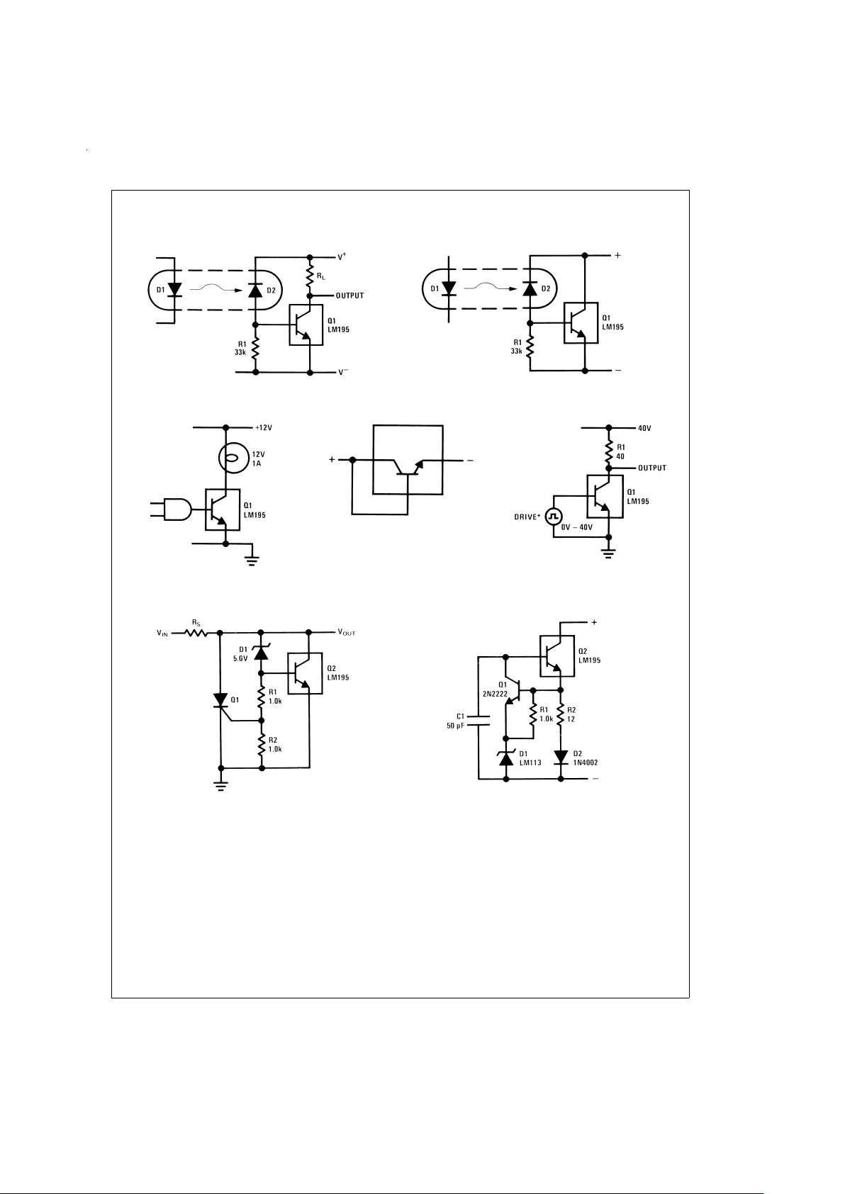
Typical Applications (Continued)
Fast Optically Isolated Switch
DS006009-19
Optically Isolated Power Transistor
DS006009-20
CMOS or TTL Lamp Interface
DS006009-21
Two Terminal Current Limiter
DS006009-22
40V Switch
DS006009-23
*
Drive Voltage 0V to ≥ 10V ≤ 42V
6.0V Shunt Regulator with Crowbar
DS006009-24
Two Terminal 100 mA Current Regulator
DS006009-25
www.national.com9
Page 10
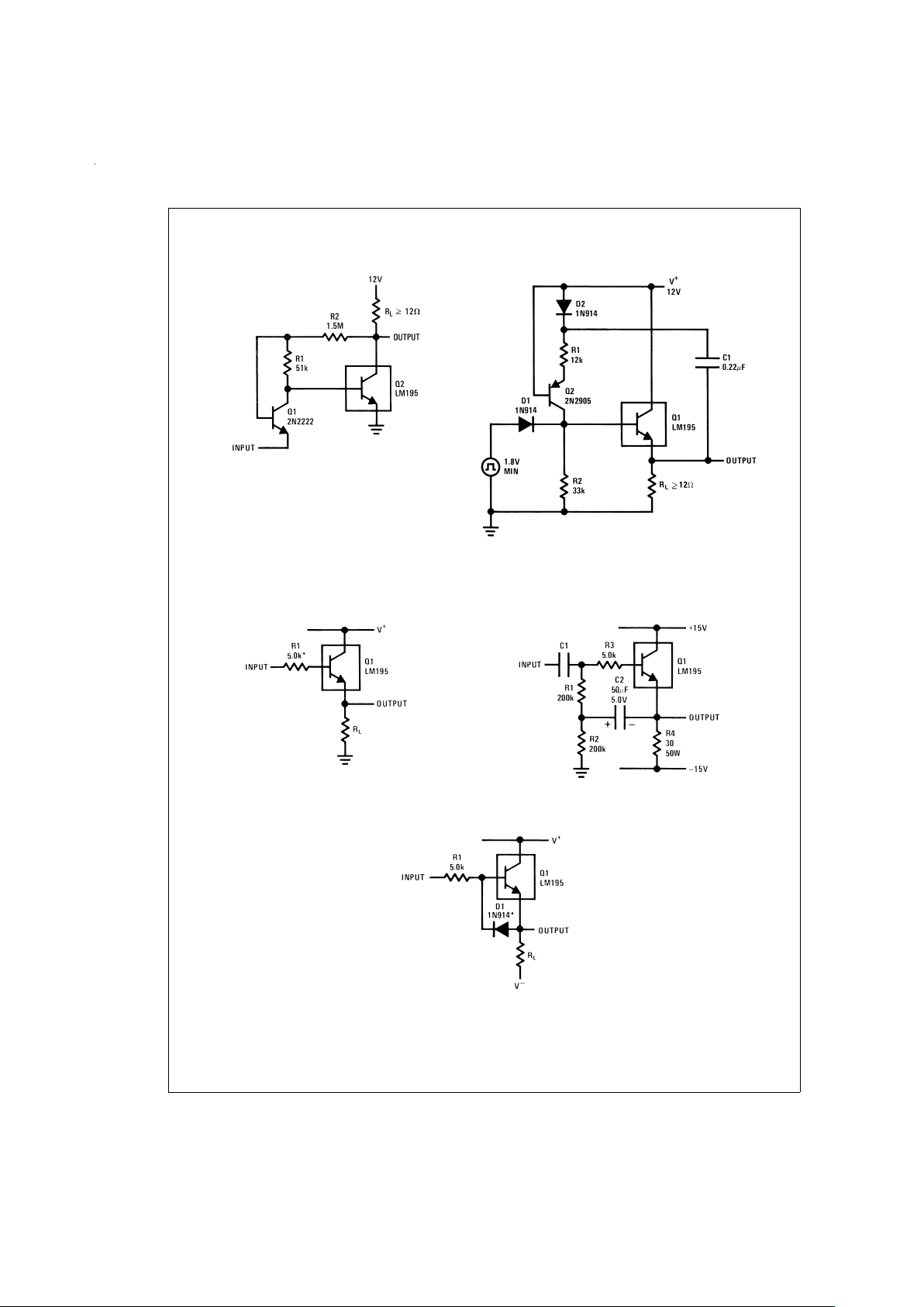
Typical Applications (Continued)
Low Level Power Switch
DS006009-26
Turn ON=350 mV
Turn OFF=200 mV
Power One-Shot
DS006009-27
T=R1C
R2=3R1
R2 ≤ 82k
Emitter Follower
DS006009-28
*
Need for Stability
High Input Impedance AC Emitter Follower
DS006009-29
Fast Follower
DS006009-30
*
Prevents storage with fast fall time square wave drive
www.national.com 10
Page 11
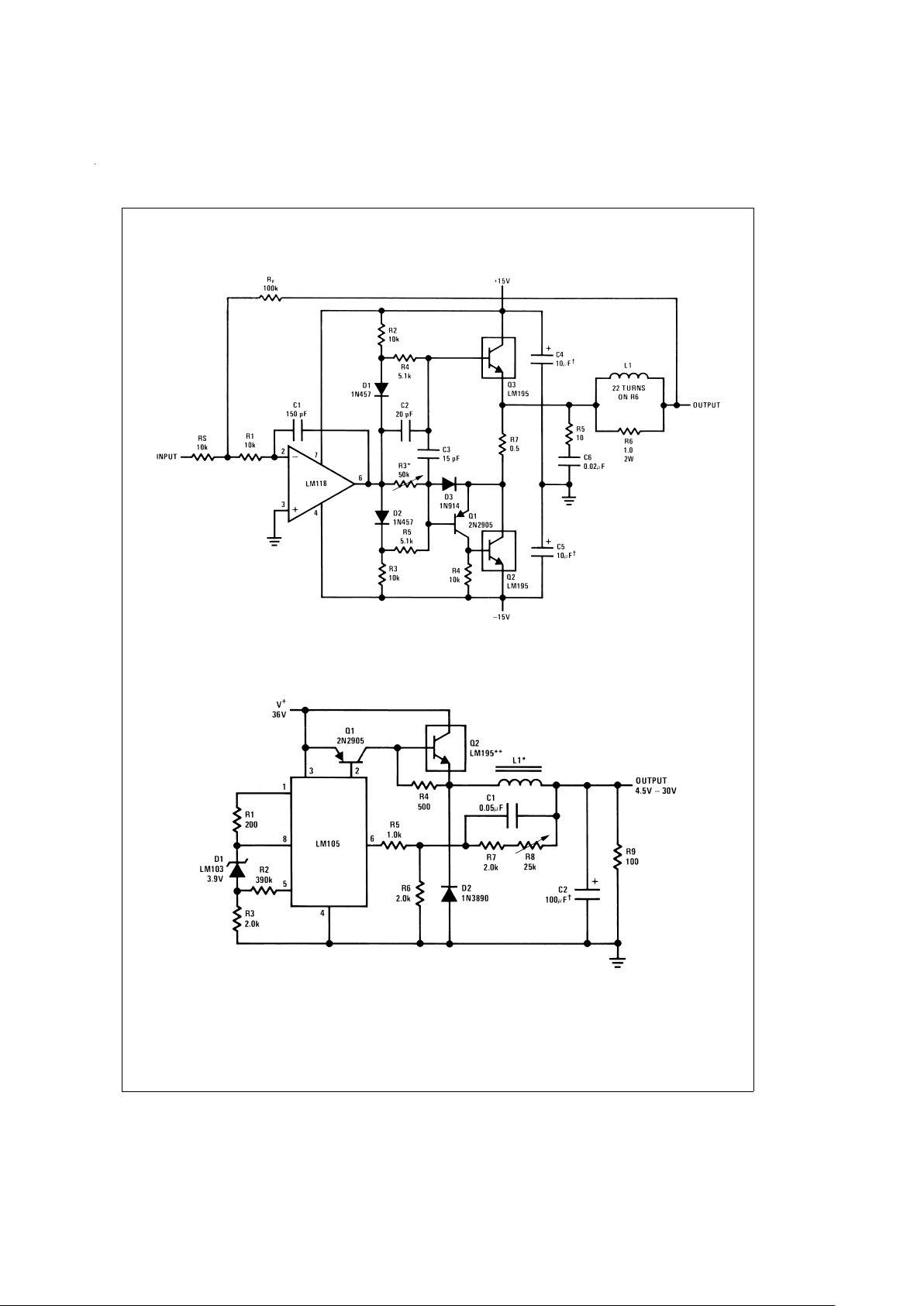
Typical Applications (Continued)
Power Op Amp
DS006009-31
*
Adjust for 50 mA quiescent current
†
Solid Tantalum
6.0 Amp Variable Output Switching Regulator
DS006009-32
*
Sixty turns wound on Arnold Type A-083081-2 core.
**
Four devices in parallel
†
Solid tantalum
www.national.com11
Page 12
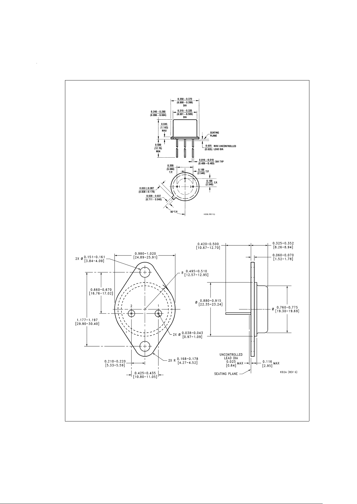
Physical Dimensions inches (millimeters) unless otherwise noted
TO-5 Metal Can Package
Order Number LM195H/883
NS Package Number H03B
TO-3 Metal Can Package
Order Number LM195K/883
NS Package Number K02A
www.national.com 12
Page 13
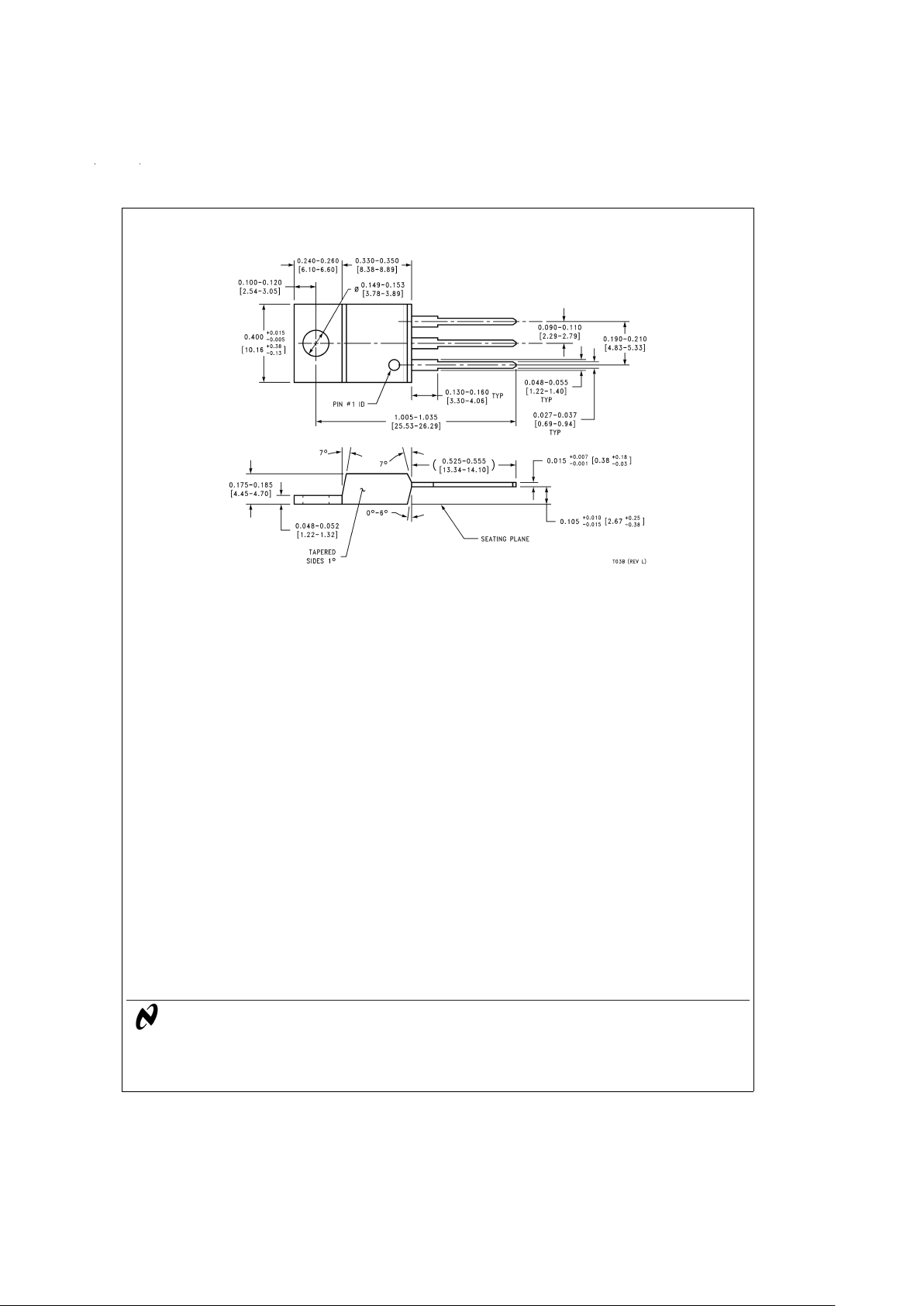
Physical Dimensions inches (millimeters) unless otherwise noted (Continued)
LIFE SUPPORT POLICY
NATIONAL’S PRODUCTS ARE NOT AUTHORIZED FOR USE AS CRITICAL COMPONENTS IN LIFE SUPPORT
DEVICES OR SYSTEMS WITHOUT THE EXPRESS WRITTEN APPROVAL OF THE PRESIDENT AND GENERAL
COUNSEL OF NATIONAL SEMICONDUCTOR CORPORATION. As used herein:
1. Life support devices or systems are devices or
systems which, (a) are intended for surgical implant
into the body, or (b) support or sustain life, and
whose failure to perform when properly used in
accordance with instructions for use provided in the
labeling, can be reasonably expected to result in a
significant injury to the user.
2. A critical component is any component of a life
support device or system whose failure to perform
can be reasonably expected to cause the failure of
the life support device or system, or to affect its
safety or effectiveness.
National Semiconductor
Corporation
Americas
Tel: 1-800-272-9959
Fax: 1-800-737-7018
Email: [email protected]
National Semiconductor
Europe
Fax: +49 (0) 1 80-530 85 86
Email: [email protected]
Deutsch Tel: +49 (0) 1 80-530 85 85
English Tel: +49 (0) 1 80-532 78 32
Français Tel: +49 (0) 1 80-532 93 58
Italiano Tel: +49 (0) 1 80-534 16 80
National Semiconductor
Asia Pacific Customer
Response Group
Tel: 65-2544466
Fax: 65-2504466
Email: [email protected]
National Semiconductor
Japan Ltd.
Tel: 81-3-5639-7560
Fax: 81-3-5639-7507
www.national.com
TO-220 Plastic Package
Order Number LM395T
NS Package Number T03B
LM195/LM395 Ultra Reliable Power Transistors
National does not assume any responsibility for use of any circuitry described, no circuit patent licenses are implied and National reserves the right at any time without notice to change said circuitry and specifications.
 Loading...