

Page 1
Phase Matrix, Inc.
585C
Instruments You Can Count On
Pulse/CW Frequency Counters
with Peak Power (595A/598A)
588C
595A
598A
• Pulse and CW Frequency Measurement to 170 GHz
• Peak Power Measurement to 26.5 GHz
• Built-in Pulse Profiling
• 200 Watt (+53 dBm) Burnout Protection
Page 1
Page 2
EIP/Phase Matrix Pulse/CW Microwave
and Millimeter-Wave Counters
Automatic Acquisition and Profiling
(Both Frequency and Power) with the Broadest
Frequency Measurement Coverage: 100Hz to 170GHz
585C / 588C full function pulse/CW counters with an
optional internal delaying pulse generator for the
ultimate in ease-of-use
595A / 598A add practical peak and CW power
measurements to the capability of the 585C/588C
Phase Matrix brings to you the broadest spectrum of
pulse and CW microwave and millimeter-wave frequency counters available today. These models offer
automatic and self contained frequency and power
profiling that is ideally suited to such applications as
chirped radar analysis, VCO measurement, and
frequency agile system analysis over a frequency range
up to 170 GHz (depending upon the model selected).
Phase Matrix’s frequency selective heterodyne technique with unique
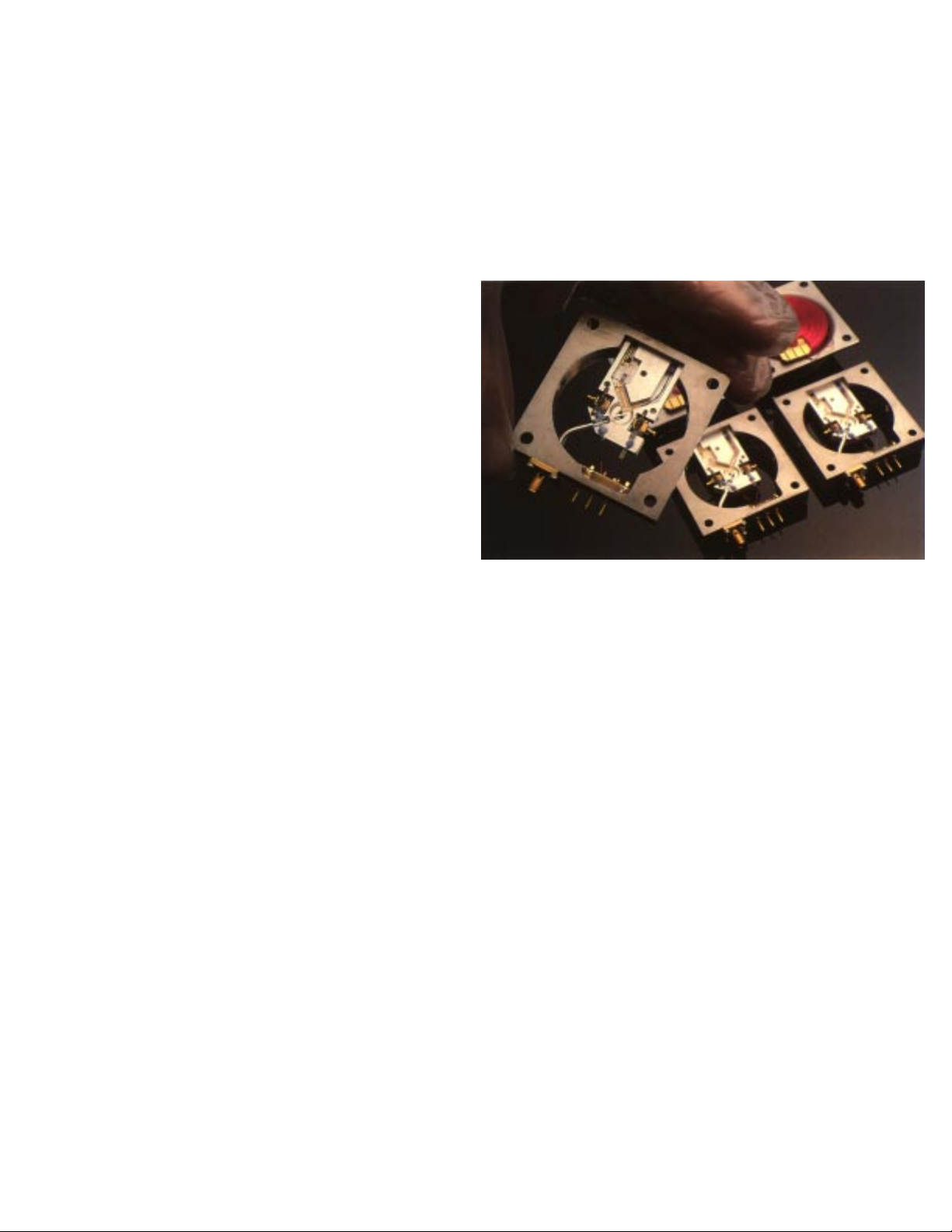
YIG filter frontend offers benefits not available in any other counter.
Pulsed or CW Measurements to 170 GHz
The 588C and 598A extended frequency capability
enables CW measurements from 100 Hz to 170 GHz, and
pulsed measurements from 250 MHz to 170 GHz.
Parameters such as frequency, power (595A/598A only),
pulse width, pulse period, or PRF can all be measured
fully automatically. The 585C/588C and the 595A/598A
will detect and measure CW, frequency modulated,
amplitude modulated, or pulsed RF signals with pulse
widths as narrow as 50nS.
Automatic Peak Power
The 595A/598A greatly simplify the measurement of
peak power in your application. By measuring the
frequency of the incoming signal, the instrument automatically corrects the power reading for the Calibration
Factor of the internal sensor. You no longer have to
manually enter the Calibration Factors or the measurement frequency. Careful design and internal calibration
tables result in excellent accuracy and repeatability.
Self-Contained Profiling of Frequency
and Power
The optional built in delaying pulse generator enables
completely self-contained frequency and power profiling
measurements. Synchronous outputs on the rear panel
show actual measurement window for viewing on an
oscilloscope. In addition, automatic measurements of
pulse width, pulse period and pulse repetition frequency
simplify your measurement task.
True profiled measurements are possible with a sample
window as narrow as 15nS. Careful design consideration
was given to accurately and automatically measuring
rapidly varying pulse bursts as might be typical in the
generation of frequency hopping or wide band chirp
signals. The Phase Matrix/EIP Model 595A/598A and 585C/
588C actually reacquire the microwave signal for each
measurement window, allowing, essentially, unlimited
frequency changes from window to window. Competitive
techniques require external gating if the frequency
changes more than 10 MHz within the detected burst.
Page 2
Page 3
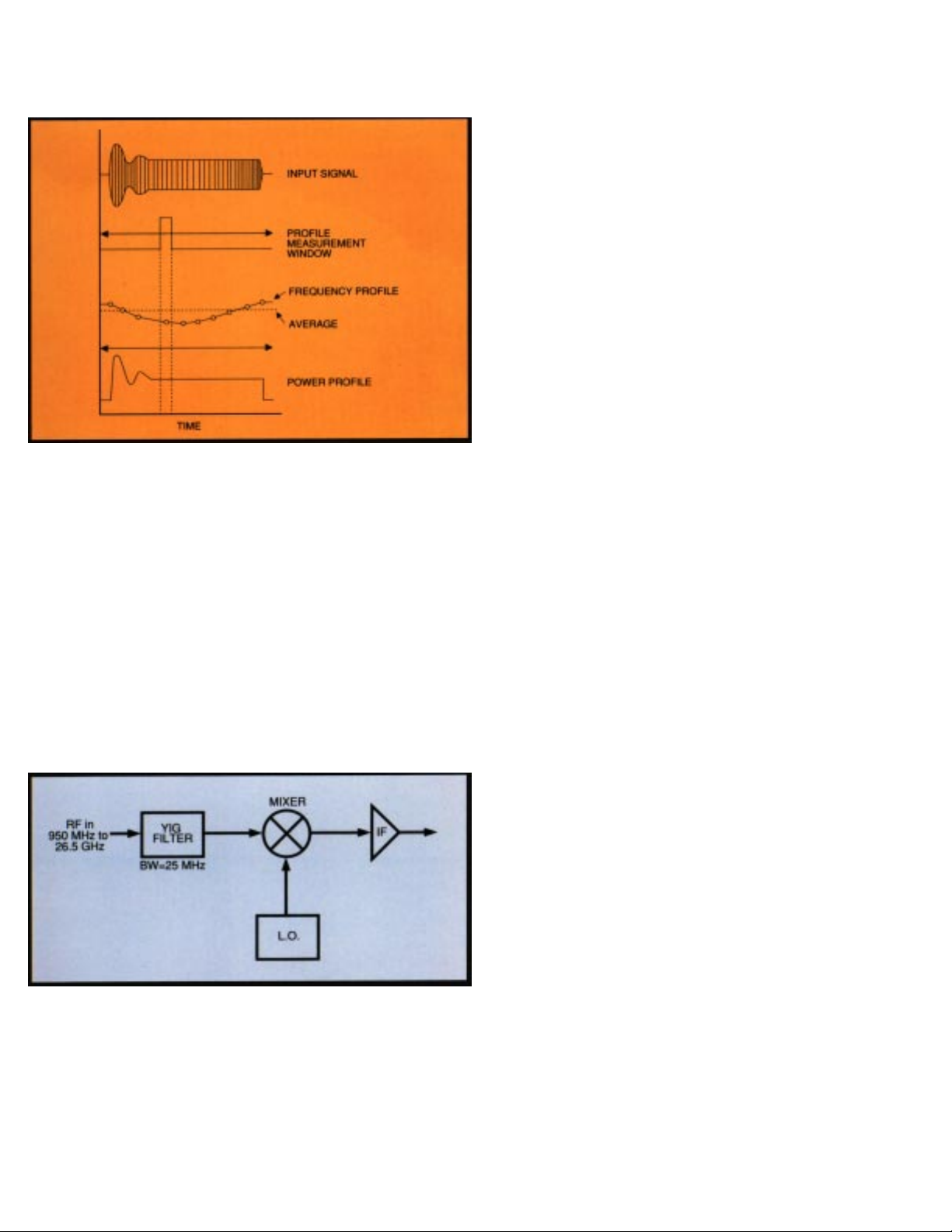
Frequency and power can be automatically profiled with
the optional internal delaying pulse generator
Unmatched Frequency Selectivity
Only Phase Matrix/EIP counters utilize the proven YIG
Preselected Heterodyne Down Conversion technique. This
spectrum analyzer type preselector prevents harmonics
and other spurious signals from interfering with the
measurement of the desired signal. Additionally, it totally
eliminates “kickback” noise. Furthermore, this frequency
selectivity allows the user to select any desired signal for
measurement of both power and frequency in a
multi-signal environment.
Graceful Overload Protection to 200 Watts
The YIG filter provides effective power limiting to protect
against burnout due to accidental application of high-level
signals, yet does not reduce sensitivity. This greatly reduces down time, especially in the hands of unskilled
operators. At remote sites, this high-level burnout protection often proves invaluable by reducing the need for
additional trips if a high power signal is accidentally
connected to the counter’s input.
Full Environmental Compliance
The Phase Matrix/EIP 595A/598A and 585C/588C are in full
EMI/RFI environmental compliance with MIL-STD-461 and
MIL-T-28800, Type III, Class 5. As well as CE certified to
EN50011 and EN50082-1.
Full Programmability
These counters have been optimized for integration into
ATE systems and have all the systems characteristics you
need for your test applications. All front panel controls,
data output format and special functions are controllable
over GPIB. Also, rear panel inputs simplify the integration
of your system.
High Stability Time Bases
All Phase Matrix Counters features the unique YIG Preselected
Heterodyne Down-Convertor.
Optional ovenized time bases provide higher accuracy and
lower cost of ownership. The time base component of error
is dramatically reduced with these high-stability time
bases. The only periodic maintenance required on the
595A/598A and 585C/588C is time base calibration. With
aging rates as low as 2 x 10⁻⁷/year, the calibration cycle
can be extended to two years while maintaining kHz
accuracy on a 20 GHz frequency measurement.
Proven Reliability
The predecessors to the Phase Matrix models 595A/598A
and 585C/588C , (EIP 585 and 588, introduced in 1985), have
become standards of reliability, achieving a field proven
MTBF in excess of 40,000 hours. Phase Matrix is so confident in the quality and reliability of these products that we
back them with an optional three year warranty.
Page 3
Page 4
Automatic Pulsed/CW Frequency and
Power Measurements
1. Automatic Pulsed Millimeter-Wave Counting up to 170 GHz with
the addition of the Model 890 cable kit and one or more harmonic mixers.
Large amounts of “chirp”, often encountered in millimeter-wave signals, can
be precisely counted using Center Frequency Mode.
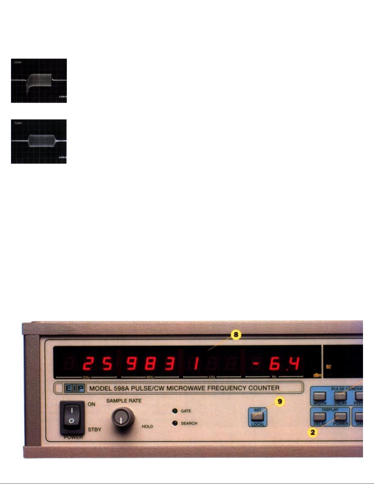
Photo 1
Photo 2
Photo 1 shows extreme video distortion
interference on the incoming RF. Photo 2
shows the same RF signal after processing
by the Phase Matrix YIG Preselected
Heterodyne Down-Convertor input filter,
with error causing video component
removed.
2. Model 595A/598A Power Measurement Capability operates over the
full operating range of the Band 1 and 2 inputs on both CW and pulsed
signals.
3. Phase Matrix’s Unique YIG Preselector provides an excellent
combination of burnout protection, sensitivity, frequency selectivity and video
immunity. The inherent frequency selectivity of the YIG filter allows counting
the highest amplitude signal even with many other signals present.
4. Optional Internal Pulse Generator makes the profiling of frequency and
power simple and automatic.
5. Pulse Width or Pulse Period can be measured and displayed with a
touch of the Pulse Width or Pulse Period key. Pulse repetition frequency can
also be easily displayed.
6. Frequency High/Low Limit allows the measurement of a lower amplitude
signal in the presence of higher amplitude signals.
7. External Switching Requirements Eliminated by the use of four
independent signal inputs that let the operator apply multiple signals and
measure any one by merely switching the band selector from the keyboard or
over the IEEE-488 Bus.
Page 4
Page 5
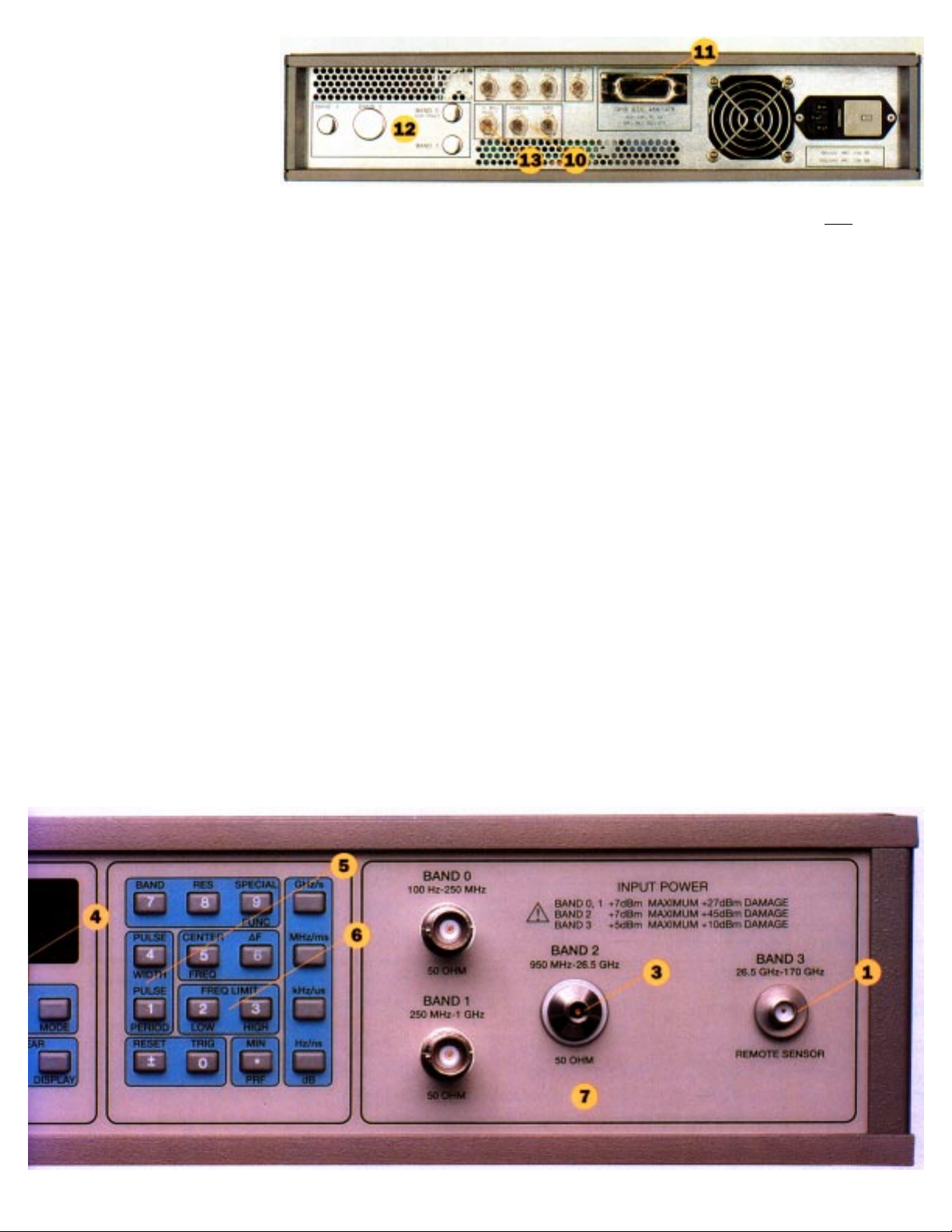
8. Dual Display For Fast, Easy Readout simultaneously provides two
important signal parameters: 1) Frequency to 1 kHz resolution, and either 2)
Power to 0.1 dB resolution or 3) Pulse width (or pulse period) to
10 nanosecond resolution. The three-digit (or six digits with special function
mode) pulse period/pulse width display utilizes a floating decimal format with
annunciators.
9. Automatic Power-Up Self-Testing and Go-to-Local allows one key
stroke to switch from remote to local, or to fully initialize the system from local.
When initialized, the instrument automatically executes power-up self-tests.
10.Precise Pulse Measurements Provided by the IF Threshold and
Gate Outputs. These convenient outputs allow the operator to monitor
exactly where within the RF pulse the sample is taken. This feature is
especially useful when using external gating for frequency profiling.
11.All Front Panel Functions and Test Sequences Can Be Placed
Under GPIB Control
via the IEEE-488 bus for ATE applications.
12.Optional Rear Panel Inputs simplify signal routing in rack-mounted
applications.
13.External Time Base Reference Capability allows the use of an external
10 MHz reference as a common system time base. Or use the output of the
optional ovenized oscillator as the system time base.
Page 5
Page 6

BAND 1 BAND 3 (Option 5804)BAND 2
S P E C I F I C A T I O N S
Frequency Range
Sensitivity
Connector
Impedance
Maximum Input
Damage Level
Amplitude
Discrimination
Frequency Limits
Center Frequency
FM Tolerance
(up to 10 MHz rate)
Acquisition Time*
Pulse
CW
Measurement Time
Pulse
CW
Gate Error
Distortion Error
Averaging Error
2
2
2
0.25 -1 GHz
-20dBM
BNC
50 Ω nominal
+7 dBm
+27 dBm
15 dB
N/A
N/A
Carrier must remain in band
AQ = { } + 0.05
AQ = { } + 0.05
2
MT = + 0.05
MT = + 0.05
GE = ±
DE = ±
1
MINPRF
1
MINPRF
(4)(PP)
(GW)(RES)
(4)
(RES)
0.07
GW
0.03
PW - (3x10⁻⁸)
AE = ± 2 x √ RES
(GW)(AVG)
595A & 585C: 0.95 - 20 GHz
598A & 588C: 0.95-26.5 GHz
0.95 - 2GHz -20 dBm
2 - 12.4 GHz -25 dBm
12.4 - 20 GHz -20 dBm
20 - 26.5 GHz -15 dBm
595A & 585C: Precision N
598A & 588C: APC 3.5
50 Ω nominal
+7 dBm
+45 dBm CW
+53 dBm peak pulsed
(≤1µS pulse, 0.1% duty cycle)
15 dB (>50 MHz seperation)
Instrument will reject signals
>50 MHz outside of Limits
Resolution: 10MHz
Instrument will reject signals
>50 MHz outside the specified Delta
Frequency.
Resolution: 10MHz
20 MHz P-P
(4x10⁻⁸)
-12
(4x10
AQ = 2(FH)[ ]
60
+ + + 0.3
MINPRF
AQ = 2(FH)[ ]
60
+ +0.3
MINPRF
(PP)
MT = + 0.05
(GW)(RES)
1
MT = + 0.05
(RES)
GE = ±
DE = ±
AE = √
0.01
GW
0.03
PW - (3x10⁻⁸)
RES
)+
(2x10⁻⁵)(PP)
GW
-12
(4x10
)+
MINPRF
(4x10⁻⁸)
MINPRF
(GW)(AVG)
26.5-170 GHz
-20 dBm (26.5 to 60 GHz)
-15 dBm (60 to 170 Ghz)
Depends on remote sensor
(See Table)
N/A
+ 5 dBm
+10 dBm
20 dB
N/A
Instrument assumes any signal
present to be in the range ±2 GHz
from the specified center frequency.
Auto Mode: 20MHz P-P
Center Freq: 150 MHz P-P
Automatic:
AQ = + +0.2
70
MINPRF
(6x10⁻³)(PP)
GW
Center Frequency:
AQ = + +0.2
AQ = +0.2
MT = + 0.05
MT = + 0.05
GE = ±
DE = ±
70
MINPRF
70
MINPRF
(4)(PP)
(GW)(RES)
4
(RES)
0.03
GW
PW - (3x10⁻⁸)
(8x10⁻⁴)(PP)
GW
0.02
AE = ± 2 x √ RES
(GW)(AVG)
Total Error
Pulse
CW
Page 6
2
TEP=±AE±GE±DE±TimeBaseError
TECW=TBError±1 count
(Based on 10 averages)
TE=±AE±GE±DE±TimeBaseError
TECW=TBError±1 count
(Based on 10 averages)
TE=±AE±GE±DE±TimeBaseError
TECW=TBError±N2 counts
(where N = )
freq
20GHz
Page 7

S P E C I F I C A T I O N S
BAND 0 (CW only)
Frequency Range 100 Hz - 250 MHz
Sensitivity -20dBm
Connector BNC
Input Impedance 50 ohms nominal
Maximum Input +7 dBm
Damage Level +27 dBm
FM Tolerance Carrier must remain in band
Measurement Time (1/RES) + 50ms
Total Error
2
TE = Time Base Error± Count
BAND 3
Model 588C/598A Frequency extended, in bands, up to 170GHz. This
Remote Frequency WaveGuide WaveGuide
Sensor Range Size Flange
091 26.5 - 40 GHz WR-28 UG-599/U
092 40 - 60 GHz WR-19 UG-383/U
093 60 -90 GHz WR-12 UG-387/U
094 90 - 110 GHz WR-10 UG-387/U
095 50 - 75 GHz WR-15 UG-385/U
096 33 - 50 GHz WR-22 UG-383/U
097 26.5 - 50 GHz K - Conn.* Coaxial
098 110 - 170 GHz WR - 6 UG-387/U
requires Option 5804, a frequency extension cabling
kit (890), and one or more of the following remote
sensors:
ST ANDARD TIME BASE
Crystal Frequency 10MHz (TXCO)
Stability
Aging Rate <1 x 10
Short Term <1 x 10
Temperature <1 x 10
Line Variation <1 x 10
-7
/month
-9
RMS, 1s average
-6,
0° to 50°C
-7
,± 10% Line voltage change
Warm-Up Time None required
Output Frequency 10 MHz square wave, 1V p – p
minimum into 50 ohms.
External Time Base Requires 10 MHz square wave,
1V p – p minimum into 300 ohms.
OPTIONAL HIGH-ST ABILITY OVENIZEDTIME BASE
Option 5809
Aging Rate per 24 hrs <5 x 10
(after 72 hours warm-up)
Short Term Stability <1 x 10
1s Average (RMS)
Temperature Stability <3 x 10
(0° - 50°C)
±10% Line Voltage Change <2 x 10
-10
-10
-9
-10
PULSED MEASUREMENTS
Pulse Width 50 ns - CW
Minimum Profile Sample 15 ns frequency/100 ns power
Pulse Repetition Frequency (PRF) 1 Hz - 4 MHz
Minimum Off Time 200 ns (will count CW)
Minimum On/Off Ratio 15 dB
PULSE P ARAMETER MEASUREMENTS
Pulse Width Pulse Period
Range 50ns - 1 s 250 ns - 1 s
Resolution 10 ns 10 ns
Measurement Points -6 dB ± 1.5 dB -6 dB ± 1.5 dB
Accuracy ±20 ns (Timebase Error x PW)
PULSE GENERA TOR SPECIFICATIONS
Min Max Resol.
Delay 74 ns 800 ms 2 ns
Width 24 ns 800 ms 2 ns
Period 100 ns 800 ms 50ns
Trig In TTL, 1kΩ input
Trig Out TTL, into 50Ω, 50 to 100 ns width
Pulse Out TTL, into 50Ω
POWER MEASUREMENT (595A AND 598A ONLY)
Measured power of signals (pulsed and CW) applied to band 1 and 2
inputs. Power and frequency are simultaneously displayed to 0.1 dB
and 100 kHz resolution, respectively. Power off sets from +99.9 dB to
-99.9 dB (0.1 dB resolution) can be input from the keyboard for via GPIB.
Frequency Range 250 MHz - 20 GHz (595A)
250 MHz - 26.5 GHz (598A)
Resolution 0.1 dB
Dynamic Range Same as counter operation range
Measurement Window 25 MHz nominal
Minimum Pulse Width 100 ns (internal or external gating)
Measurement Time Frequency measurement time plus one
gate time plus 150 msec - CW
Accuracy ±0.5 dB CW typical (25°C, input padded
by 3 dB)
±1.5 dB CW typical (25°C, input padded
by 3 dB, 1µsec measurement window,
10% duty cycle)
Repeatability ±0.3 dB typical CW to 20 GHz
±0.5 dB typical CW to 26.5 GHz
±0.3 dB typical pulse to 20 GHz (1µsec
measurement window, 10% duty cycle)
±0.8 dB typical pulse to 26.6 GHz (1µsec
measurement window, 10% duty cycle)
Note 2 AE = RMS averaging error (Hz) FH = Difference between Frequency Limit High and Low (Hz)
AQ = Aquisition time (seconds)
AVG = Number of averages GE = Gate error (Hz)
DE = Distortion error (Hz) TE = Total error (Hz)
*K-Connector is a registered trademark of Wiltron Company
Specifications subject to change without notice.
GW = Logical AND of inhibit input and pulse width -3 x 10
MinPRF = Minimum PRF coutner setting (Hz); for MinPRF>1.2 kHz, use MinPRF = 1200
MT = Measurement Time (seconds)
PP = Pulse period (seconds)
PW = Pulse width (seconds)
RES = Counter resolution setting (Hz); for RES>1MHz, use RES = 10%
-8
(seconds)
Page 7
Page 8

GENERAL
Dimensions 3.5 in H x 16.75 in W x 14 in D
(8.9 cm H x 42.6 cm W x 35.6 cm D)
Weight ≈ 35 lbs., 15.9 Kg
Shipping Weight ≈ 40 lbs., 18.2 Kg
Operating Temperature 0 to 50°C
Power 100/120/200/240 Vac ± 10%
50 - 400 Hz, 100 VA typical
Resolution 1 Hz to 1 GHz
Gate Time 1 s to 1µs (dependent upon resolution)
ORDERING INFORMA TION
Model 585C Pulse/CW Microwave Frequency Counter, 20 GHz
Model 588C Pulse/CW Microwave Frequency Counter, 26.5 GHz
Model 595A Pulse/CW Microwave Frequency Counter, 20 GHz
with Peak Power Measurement
Model 598A Pulse/CW Microwave Frequency Counter, 26.5 GHz
with Peak Power Measurement
FREQUENCY EXTENSION ACCESSORIES FOR MODEL 588C/598A
Waveguide Waveguide
Size Flange
890 Fr equency Extension Cable Kit
091 Remote Sensor 26.5 - 40 GHz WR-28 UG -599/U
092 Remote Sensor 40 - 60 GHz WR-19 UG-383/U
093 Remote Sensor 60 - 90 GHz WR-12 UG-387/U
094 Remote Sensor 90 - 110 GHz WR-10 UG-387/U
095 Remote Sensor 50 - 75 GHz WR-15 UG-385/U
096 Remote Sensor 33 - 50 GHz WR-22 UG-383/U
097 Remote Sensor 26.5 - 50 GHz K-Conn Coaxial
098 Remote Sensor 110 - 170 GHz WR-6 UG-387/U
Note: Remote Sensors require cable kit 890 and extended frequency Option 5804.
Warranty 1 Year Standard
Computer Interface GPIB (IEEE-488/1987)
Certifications CE Certified for EMC to
EN50011 and EN50082-1
CE Certified for Safety to IEC
1010-1 (1990)
(Extendable to 3 years)
OPTIONS
5803 Rear Panel Input Connectors
5804 Band 3 Frequency Extension Module
Available on Model 588C/598A only.
5809 Ovenized High Stability Timebase
(Aging Rate: <5 x 10
5810 Delaying Pulse Generator
14 2 Year Warranty Extension (to 3 years total)
15 MIL-STD 45662A Data and Certification
-10/
day)
ACCESSORIES
010 Transit Case
021 Rack Mount Kit with Handles
022 Rack Mount Kit without Handles
031 Extra Operations Manual
(one supplied at no cost)
032 Maintenance and Service Manual (includes
operations information)
043 Service Kit
050 Sof-Pac Carrying Case
101 Chassis Slide Kit with Handles
(includes 021)
102 Chassis Slide without Handles
(includes 022)
For More Information Contact:
Phase Matrix, Inc.
109 Bonaventura Drive
San Jose, CA 95134 U.S.A
TEL: (408) 428-1000
FAX: (408) 428-1500
TOLL FREE: (877) 4PhaseM
EMAIL: sales @phasematrix.com
Copyright ©1999, All Rights Reserved, Phase Matrix, Inc.
Revision 10/99
Printed in the USA
Specifications subject to change without notice.
Datasheet Prepared By:
Sonic Imagery Labs and
PixelJam Productions
Page 8
 Loading...