

Page 1
Phase Matrix, Inc.
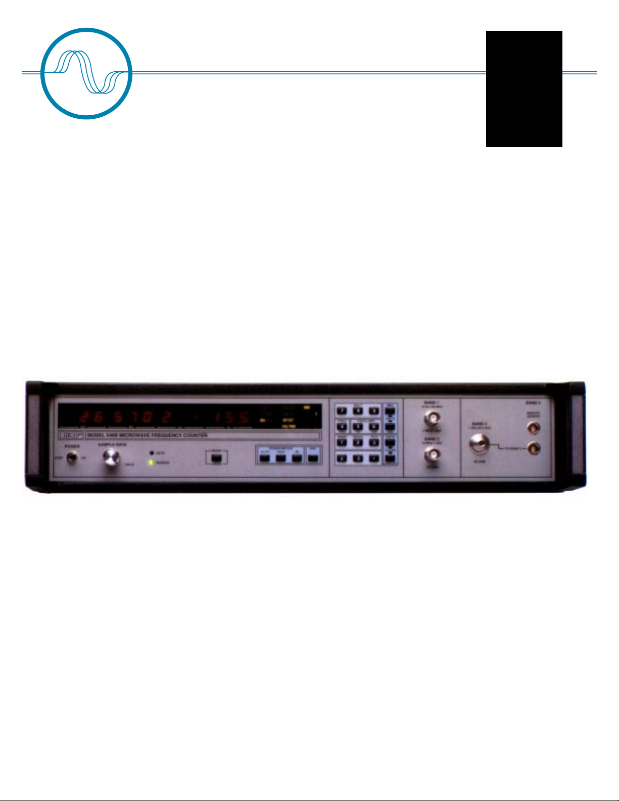
545B
Instruments You Can Count On
Full Function CW Microwave
Frequency Counters with
Selective Power
Measurement
548B
Phase Matrix, Inc.
EIP 545B and 548B
CW Frequency Counters
• Keyboard controlled frequency limit selection
• Power Measurement to 0.1 dB resolution
• Power Measurement accuracy to ±0.5 dB typical
• -30 dBm sensitivity
• 200 Watt (+53 dBm) peak damage protection
• 10 dB automatic amplitude discrimination
• 200msec acquisition time
• Up to 800 MHz/sec tracking speed
• 20MHz P-P FM tolerance up to a 10 MHz rate
Page 1
Page 2
Phase Matrix / EIP 545B and 548B. . . .
Full Function Microwave Frequency Counters
The Ideal Benchtop Counters
The combination of accuracy, simple operation, and the widest range of standard
features and options available ina microwave counter makes the 545B/548B family
the best choice for your R&D lab or production test bench. Wherever a microwave
counter has multiple duties and a variety of applications to meet, only a full function counter with YIG-tuned preselection can provide the capabilities that you
need.
The 545B measures CW, FM and AM frequencies from 10 Hz to 20 GHz, and the
548B extends that range up to 26.5 GHz. With simultaneous power measurement
capability, and options for a high stability time base, these high performance
counters are ideally suited for applications in:
• Carrier signal measurement
• Transmitter frequency verification
• Channel specific signal measurements
• Production Line testing
• R&D Labs
• ATE
Only Phase Matrix counters offer the unique
YIG-preselected heterodyne technique.
Unsurpassed Burnout Protection
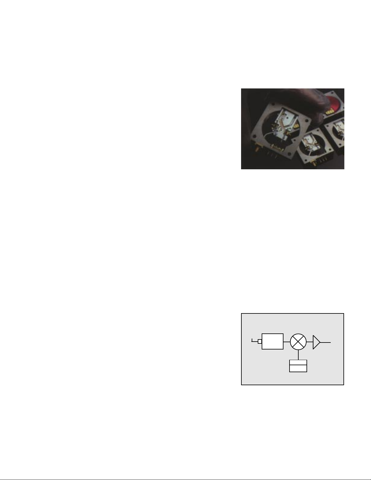
Typically found in high performance spectrum analyzers; only Phase Matrix
counters feature a YIG-preselected microwave input, which provides unparralled
burnout protection, FM tolerance and frequency selectivity. The YIG preselector
works like a tunable bandpass filter, preventing harmonics and other out-of-band
spurious signals from interfering with measurement of the desired signal. It also
protects the counter from accidental application of high level signals (up to 200
watts peak), reducing downtime and the associated high cost of repairing
damaged microwave circuitry.
Selective Frequency and Power Measurements
With a single connection, the 545B and 548B can simultaneously measure and
display the input signals frequency and power level in the microwave band,
eliminating the need for a seperate microwave power meter. Within the 25MHz
bandwidth of the YIG-preselector, only the selected signals frequency and power
level are measured. Signals to be analyzed are selected by keystroke entry of an
individual center frequency, or search a range between a low and high frquency
limit. This signal selectivity, combined with 20MHz of FM tolerance at all rates up to
10MHz, allows the 545B and the 548B to make accurate frequency and power level
measurements even while the input signal is carrying traffic; there is no need to
take the transmitter, or adjacent channels, off the air for routine checks.
RF Input
950MHz to
26.5 GHz
YIG Filter
BW=25MHz
All Phase Matrix Counters feature the unique
YIG Preselected Heterodyne Down-Convertor.
MIXER
SRD
L.O.
IF to Count
Circuitry
Page 2
Page 3
Phase Matrix / EIP 545B and 548B. . . .
The Ultimate Benchtop Instrument
Frequency Extension to 110 GHz
Option 06 provides the ability to extend the frequency range of your 548B, in bands, up
to 110 GHz. Remote sensors allow you to reach out to connect to virtually any wave
guide system without the complications of the additional plumbing necessary to bring
the signal to your counter. A wide selection of sensors provides measurement
capability in the wave guide band that you are working in now, and the flexibility to
change as your application changes without having to purchase another counter.
Frequency Limits
Automatic amplitude discrimination enables the 545B/548B counters to automatically
select and measure the input signal with the highest level, and ignore all other harmonics and other spurious signals that are present. "Frequency Limits" extend this
signal selection capability by allowing you to select upper and lower limits, The
counter will measure the frequency and power level of only the highest level signal
within these limits - even if there are higher level signals present at the counters input.
This gives you the ability to measure the frequency and power of a low level signal
(such as a harmonic) even when a signal of much higher level (the fundamental) is
present.
Power Measurement
The 545B/548B family of microwave counters offers the optional ability to simultaneously measure both the frequency and power level through the same input. This
often eliminates the need for a separate microwave power meter. With the 25 MHz
bandwidth of the YIG tuned preselector, power measurement is made only of the
displayed signal, not of its harmonics or other signals present. Thus you can
simultaneously measure and display both frequency and power of individual signals in
a multisignal environment. Easy keystroke entry of power offsets can be used to
measure power deviation from a reference, or to compensate for losses in external
hook-ups such as cable and attenuator losses.
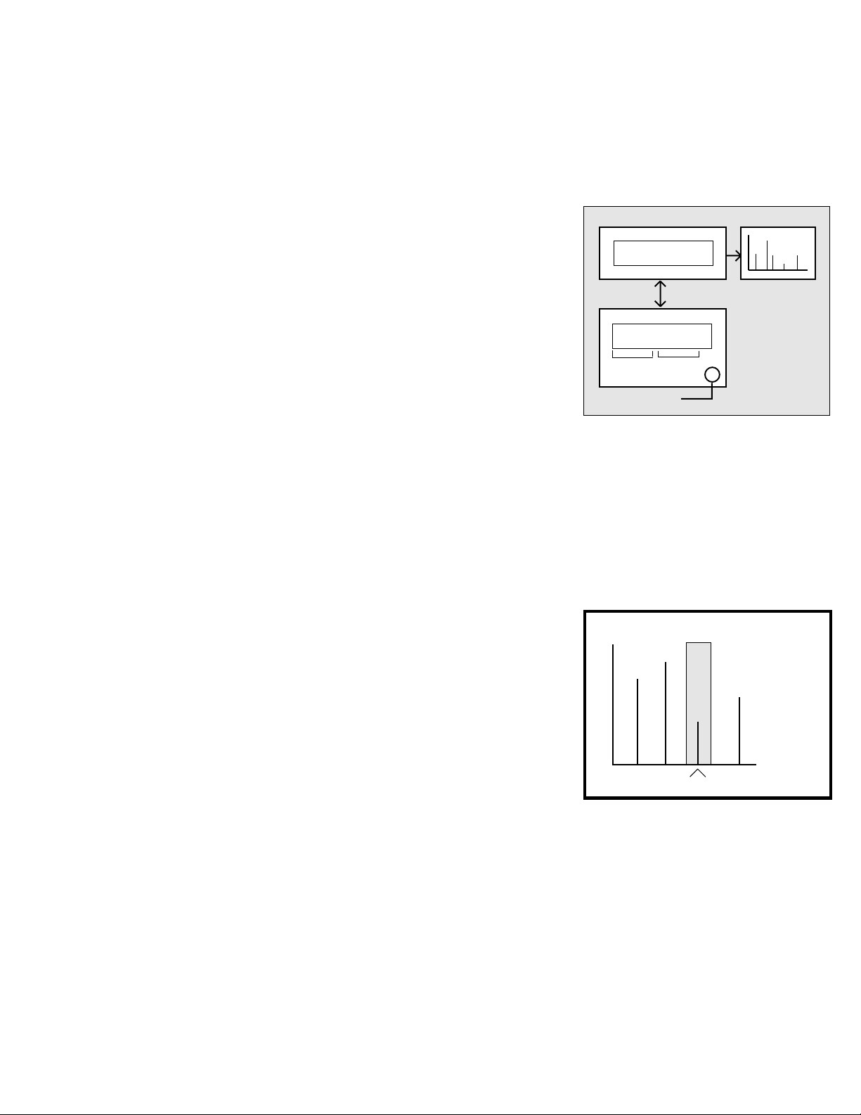
GPIB Controller CRT or Plotter
Program
PhaseMatrix 545B/548B
Display
Freq. Power
Signal Under Test
Frequency domain analysis can be accurately
and quickly performed by utilizing the counter’s
selective frequency and selective power
measurement capabilities.
POWER
(dBm)
+10
0
-5
-30
FREQUENCY
MEASURED SIGNAL
Proven Reliability
This counter has become the standard in reliability, achieving over 26,000 hours
(12.5 years) of field-proven MTBF. The high performance, economy and compact
configuration of the 545B and 548B make them the ideal choice for your
production and R&D applications on the bench.
The frequency selective operation of the
counters allows measurement of any individual
signal’s frquency and power in a multi-signal
environment.
Page 3
Page 4

SPECIFICATIONS
MODEL 545B and 548B
Frequency Range
Sensitivity
Impedance
Connector
Input Coupling
Maximum Operating Level
Damage Level
Acquisition Time
Standard
Center Frequency Mode
Automatic Amplitude
Discrimination
BAND 1 BAND 2
10 Hz-100 MHz
25mV rms
1MΩ/20pF
BNC (female)
DC
120 V rms*
150 V rms*
N/A
N/A
N/A
10 MHz-1 GHz
-20dBm
50 Ohms
BNC (female)
AC
+10 dBm
+27 dBm
<50mS
N/A
N/A
BAND 3
1-20 GHz (545B)
1-26.5 GHz (548B)
-30 dBm 1-12.4 GHz
-25 dBm 12.4 GHz-20 GHz
-20 dBm 20 GHz-26.5 GHz
50 Ohms
Precision Type N-female (545B)
APC 3.5-female (548B)
AC
+10 dBm
+45 dBm (30 watts) continuous
+53 dBm (200 watts) peak pulsed
(<1uS PW, 0.1% duty)
<200ms
<20ms
10 dB
FM Tolerance
Maximum Tracking Speed
VSWR
Center Frequency Mode
Frequency Limits
BAND 4 (option 06, 548B only)
Frequency Range
Sensitivity
Connector
Maximum Operating Level
Damage Level
Acquisition Time
Amplitude Discrimination
Carrier remains in
band
Carrier remains in
band
N/A
N/A
N/A
26.5 GHz - 110 GHz
-25 dBm typical
Depends on remote sensor
+5 dBm
+10 dBm
<1 second typical
10 dB
Carrier remains in
band
>800MHz/sec
typical
2.5:1 typical
N/A
N/A
20 MHz P-P up to 10MHz rate
>800MHz/sec typical
2.5:1 typical
Keyboard controlled. Unit will measure
signal within ± 5 MHz
of entered frequency. Signals of equal
amplitude must be seperated by 40 MHz
Keyboard controlled. Unit will measure
largest signal within set limits. Signals
outside desired range must be seperated by
≥200 MHz (typical) from either limit.
*Above 1KHz, decreases @ 6dB/octave
down to 3.0 V rms
Page 4
Page 5

SPECIFICATIONS
Power Measurement
Time Base: Standard TCXO
Frequency Range
Accuracy
Resolution
Minimum Level
Display
Offset Range
Offset Resolution
Offset Input
Measurement Time
Measurement Window
1-20 GHz (545B)
1-26.5 GHz (548B)
±1.2 dB typical (0˚ to 50˚C, input padded by 3 dB)
±0.5 dB typical (25˚C, input padded by 3 dB)
Power: ±0.1 dB
Frequency: 100 kHz to 1 GHz (selectable) via GPIB
1 Hz to 1 GHz (selectable) via GPIB
Equal to counter sensitivity
Simultaneous frequency and power reading
-99.9 dB to +99.9 dB
0.1 dB
Keyboard or optional GPIB
1 Gate Time + 50ms + Freq Measurement Time
25 MHz nominal
Crystal Frequency
Stability
Output Frequency
External Time Base
GPIB (IEEE-488/1978) Programmabilty
GPIB
General
Warranty
Frequency Resolution
Display
Frequency Accuracy
Test
Sample Rate
Reset
Frequency Offset
Frequency Multiply
Computer Interface
Certifications
Operating Temperature
Power
Net Weight
Shipping Weight
Dimensions
Standard Accessories
10 MHz
Aging Rate
Short Term
Temperture
Line Variation
10 MHz square wave, 1V P-P min into 50Ω
Requires 10 MHz, 1VP-P min into 300Ω
Functions, special functions and diagnostics are programmable.
Address settable from the front panel. Compatible IEEE STD-488.
SH1, AH1, T5, L3, SR1, RL1, DC1 and DT1 implimented.
1 year Standard (Extendable to 3 years)
Selectable 0.1 Hz to 10 MHz in band 1, 1 Hz to 1 GHz in bands 2 and 3.
12-digit LED sectionalized to read GHz, MHz, kHz, Hz or GHz, MHz,
kHz, dBm.
± 1 count ± time base error.
Front panel selected service diagnostics and user information.
Varies time between measurements, from 0 sec to 10 sec.
HOLD freezes display indefinitely.
Resets display to zero and initiates new acquisition.
Displayed frequency is offset by the entered value to 1 Hz resolution.
Displayed frequency is multiplied by an entered integer from 1 to 99 and
displayed to 1 kHz resolution. OFFSET is added or subtracted to obtain
y = mx ±b result.
GPIB (IEEE 488/1978)
CE Certified for EMI/RFI to EN50011 and EN50082-1
Certified for Safety to IEC 1010-1 (1990)
0˚ to 50˚C.
100/120/140/200/220/240/VAC ±10%, 50 to 400 Hz; 60 VA typical.
~ 26 lbs. (11.8 kg).
~ 32 lbs. (14.5 kg).
3.5” H x 16.75” W x 14.0” D (89 mm H x 425 mm W x 356 mm D).
Power cord, Operating manual.
<1x10⁻⁷/month, <1x10⁻⁶/year
<1x10⁻⁹ rms for one sec. averaging time
<1x10⁻⁶, 0˚ to 50˚C
<1x10⁻⁷, ±10% line voltage
Page 5
Page 6

SPECIFICATIONS
OPTION 01
OPTION 02
OPTION 05
Stability
Frequency Extention Accessories
Digital to Analog Converter
Option 01 will convert any three consecutively displayed digits to an analog voltage output. A display of 000
produces 0 volts output; 999 produces 0.999 volts full scale. Output is updated after every display update.
Power Measurement
Option 02 measures power of signals applied to the Band 3 input. Power and frequency are simultaneously
displayed to 0.1 dB and 100kHz resolution, respectively. Option 02 also allows power offsets from -99.99 to +99.99 dB
(0.1 dB resolution) to be input from the keyboard or via GPIB.
High Stability Ovenized Timebase
Aging Rate
Short Term
Temperture
Line Variation
Retrace
590 Frequency extention cable kit
091 26.5-40 GHz remote sensor, waveguide
092 40-60 GHz remote sensor, waveguide
093 60-90 GHz remote sensor, waveguide
094 90-110 GHz remote sensor, waveguide
095 50-75 GHz remote sensor, waveguide
096 33-50 GHz remote sensor, waveguide
097 26.5-50 GHz remote sensor, coax
-10
<5x10
/day, (After 24 hour warm up).
-10
<1x10
rms for one sec. averaging time
<3x10⁻⁸, 0˚ to 50˚C
-10
<2x10
, ±10% line voltage
<5x10⁻⁹ of final value 10 minutes after counter is turned on at 25˚C
Note: All remote sensors require cable kit 590 and
extended frequency Option 06
ORDERING INFORMATION
MODEL 545B
MODEL 548B
Options
Accessories
10 Hz - 20 GHz Microwave Frequency Counter
10 Hz - 26.5 GHz Microwave Frequency Counter
01
02
05
06
09
10
14
15
010
020
031
032
040
For More Information Contact:
Phase Matrix, Inc.
109 Bonaventura Dr.
San Jose, CA. 95134 USA
tel: 408-428-1000
fax: 408-428-1500
toll free: 877-4PhaseM
www.phasematrix.com
Specifications and ordering
information subject to change without notice.
Copyright ©1999 Phase Matrix, Inc. All Rights Reserved
Printed in the USA
Revision 10/99
Digital to Analog Converter
Power Measurement
High Stability Ovenized Time Base
Frequency Extension
Rear Panel Signal Input
24” Chasis Slides
2 Year Warranty Extension (3 years total)
MIL-STD 45662 (ANSI Z540-1:94)
Transit Case
Rack Mount Kit
Extra Operating Manual (one supplied at no cost)
Maintenance and Service Manual (includes operation information)
Service Kit
Datasheet Prepared By:
Sonic Imagery Labs and
Page 6
PixelJam Productions
 Loading...