

Page 1

PRELIMINARY DATA SHEET
53248-102
POWER CONTROLLER
28 VDC SOLID STATE
Mii
HYBRID MICROELECTRONICS
PRODUCTS DIVISION
Features:
Isolated Control
•
Isolated Status Output
•
Latched Fault Protection
•
Thermal Shutdown
Undervoltage & Overvoltage Shutdown
Current Limit
Short Circuit Protection
DESCRIPTION
The 53248-102 is a 28 VDC Solid State High Side Power Controller (SSPC) that is designed to replace
electromagnetic circuit breakers rated at up to 10 amperes. It is a high side switch utilizing N-channel vertical power
FET technology with integral charge pump. The SSPC provides a status output that signals a variety of conditions
including over temperature shutdown, overvoltage or undervoltage, over-current or short circuit. It will trip off and latch
for any of the above conditions until reset by recycling of the control input.
Using vertical MOSFET technology, the SSPC offers extremely low “ON” resistance. This results in very low power
dissipation, which allows operation over the temperature range of –40°C to +85°C with minimal heat sinking.
Applications:
Power Distribution In Land/Air/Launch Vehicles
•
Motor Switch
•
Displays/Lamps/Controls
•
Industrial Automation
•
Switching Heaters
•
Test Equipment
•
Machine Control Equipment
•
•
Medical Lab Equipment
ABSOLUTE MAXIMUM RATINGS
= 25°C unless otherwise specified)
(@ T
C
Input Control Current...................................................................................................................................................... 10 mA
Reverse Input Voltage (Control to Signal Ground)..................................................................................................... - 5 VDC
Pins to Case Isolation.............................................................................................................................................. 1000 VDC
Input-Output Isolation .............................................................................................................................................. 1000 VDC
Lead Temperature (15 seconds) ................................................................................................................................. +300°C
Junction Temperature ..................................................................................................................................................+150°C
Blocking Voltage ……………………………………………………………………………………………………… 63 VDC
Micropac Industries cannot assume any responsibility for any circuits shown or represent that they are free from patent infringement.
Micropac reserves the right to make changes at any time in order to improve design and to supply the best product possible.
MICROPAC INDUSTRIES, INC. HYBRID MICROELECTRONICS PRODUCTS DIVISION • 905 E. Walnut St., Garland, TX 75040 • (972) 272-3571 • Fax (972) 494-2281
www.micropac.com E-MAIL: [email protected]
05/16/01
Page 2
PRELIMINARY DATA SHEET 53248-102
28 VDC SOLID STATE POWER CONTROLLER
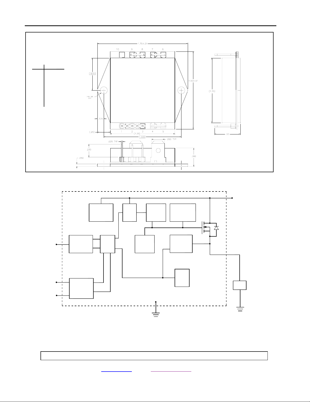
Package Configuration
PIN # FUNCTION
1
CONTROL
STATUS
2
SIGNAL GND
3
OUTPUT
4
5
OUTPUT
POWER IN
6
POWER IN
7
8
POWER GND
POWER GND
9
NC
10
Dimensions: inches
Functional Block Diagram
CONTROL
STATUS
SIGNAL GND
ISOLATION/
CONTROL
ISOLATION/
STATUS
VOLTAGE
REGULATOR
LOGIC
O/V
U/V
CURRENT
LIMIT
CHARGE
PUMP
GATE
PROTECTION
OUTPUT
DETECTION
TEMP
SENSE
(POWER GND)
POWER
IN
OUTPUT
LOAD
Micropac Industries cannot assume any responsibility for any circuits shown or represent that they are free from patent infringement.
Micropac reserves the right to make changes at any time in order to improve design and to supply the best product possible.
MICROPAC INDUSTRIES, INC. HYBRID MICROELECTRONICS PRODUCTS DIVISION • 905 E. Walnut St., Garland, TX 75040 • (972) 272-3571 • Fax (972) 494-2281
www.micropac.com E-MAIL: [email protected]
05/16/01
Page 3

PRELIMINARY DATA SHEET 53248-102
28VDC SOLID STATE POWER CONTROLLER
SPECIFICATIONS
25°C unless otherwise specified)
(@ T
C
Control Function
Input Type......................................................................................................... 1.5 kΩ resistor in series with 1.3 V drop LED
Turn-on Control Current ..........................................................................................................................................3 mA (min)
Turn-off Control Current ....................................................................................................................................... 10 µA (max)
Status Function
Open Collector transistor, V
Output High is V
, Output Low is +0.4 V (max) @ ICC = 10 mA (max)
CC
Status output transistor off (logic high) indicates unit is off.
Status output transistor on (V ≤ 0.4 VDC) indicates unit is on.
Power Circuit
Supply Voltage (for normal operation) ................................................................ 5 VDC (min), 28 VDC (typ), 40 VDC (max)
Continuous Current ........................................................................................................................................................... 10 A
On-state Resistance, T
On-state Resistance, T
Minimum Output Voltage Drop (I
Power Dissipation at T
C
Power Output Leakage Through Load (off state, V supply = 28VDC) ..........................................................................15 µA
Quiescent Current (@ No load) (V supply = 28VDC) ..................................................................... 8 mA (typ), 15 mA (max)
= +40 VDC (max)
CC
@ 25°C (IL ≥ 5A) .....................................................................................................................38 m
j
@ 150°C (I
j
5A)....................................................................................................................80 m
≥
L
= 0.5A) ..................................................................................................................... 50 mV
L
= 25°C and Full Load.................................................................................................................. 4 W
Ω
Ω
Temperature Range
Operating (Case) ..............................................................................................................................................-40°C to +85°C
Storage .......................................................................................................................................................... -55°C to +150°C
Thermal Resistance
Junction to Case............................................................................................................................................................3 °C/W
Physical Characteristics
See Package Configuration
Timing at 28 VDC (I
=1A)
L
Turn-on Time ................................................................................................................................................... 300 µsec (max)
Status Turn-on Delay ......................................................................................................................................400 µsec (max)
Turn-off Time ................................................................................................................................................... 300 µsec (max)
Status Turn-off Delay ......................................................................................................................................400 µsec (max)
Micropac Industries cannot assume any responsibility for any circuits shown or represent that they are free from patent infringement.
Micropac reserves the right to make changes at any time in order to improve design and to supply the best product possible.
MICROPAC INDUSTRIES, INC. HYBRID MICROELECTRONICS PRODUCTS DIVISION • 905 E. Walnut St., Garland, TX 75040 • (972) 272-3571 • Fax (972) 494-2281
www.micropac.com E-MAIL: [email protected]
05/16/01
Page 4
PRELIMINARY DATA SHEET
53248-102
28VDC SOLID STATE POWER CONTROLLER
FUNCTIONAL DESCRIPTION
The 53248-102 SSPC offers a wide range of features. These include overvoltage and undervoltage shutdown,
overcurrent and short circuit protection provided by temperature sensing, built in transient protection and fully
optically isolated control and status lines. The overcurrent and short circuit protection are achieved through the
temperature sensing feature of the controller. Overcurrent is sensed through the increasing R
increase power dissipation in the pass element, which additionally causes a further increase in R
junction temperature approaches +150°C, drive to the pass element is decreased, causing V
When the pass element temperature is between +150°C and +175°C, the drive to the pass element is removed
and current flow ceases. When the control is recycled and if the fault condition has been removed the device
will resume operations. Status will indicate a fault condition until the fault is removed.
Peak Current Limits vs. Junction Temperature* Overvoltage and Undervoltage Limits
Junction Temperature Min Typ Max Unit
Overvoltage +42 VDC to +52 VDC
-40°C --- --- 74 A Undervoltage +2.4 VDC to +4.5 VDC
+25°C --- 44 --- A Overvoltage hysteresis Typical +0.2 VDC
+150°C 24 --- --- A Undervoltage hysteresis Typical +0.2 VDC
= –40°C to +150°C)
(T
j
*Peak Duration
causing
DS(ON)
DS(ON)
to increase.
DS
. As
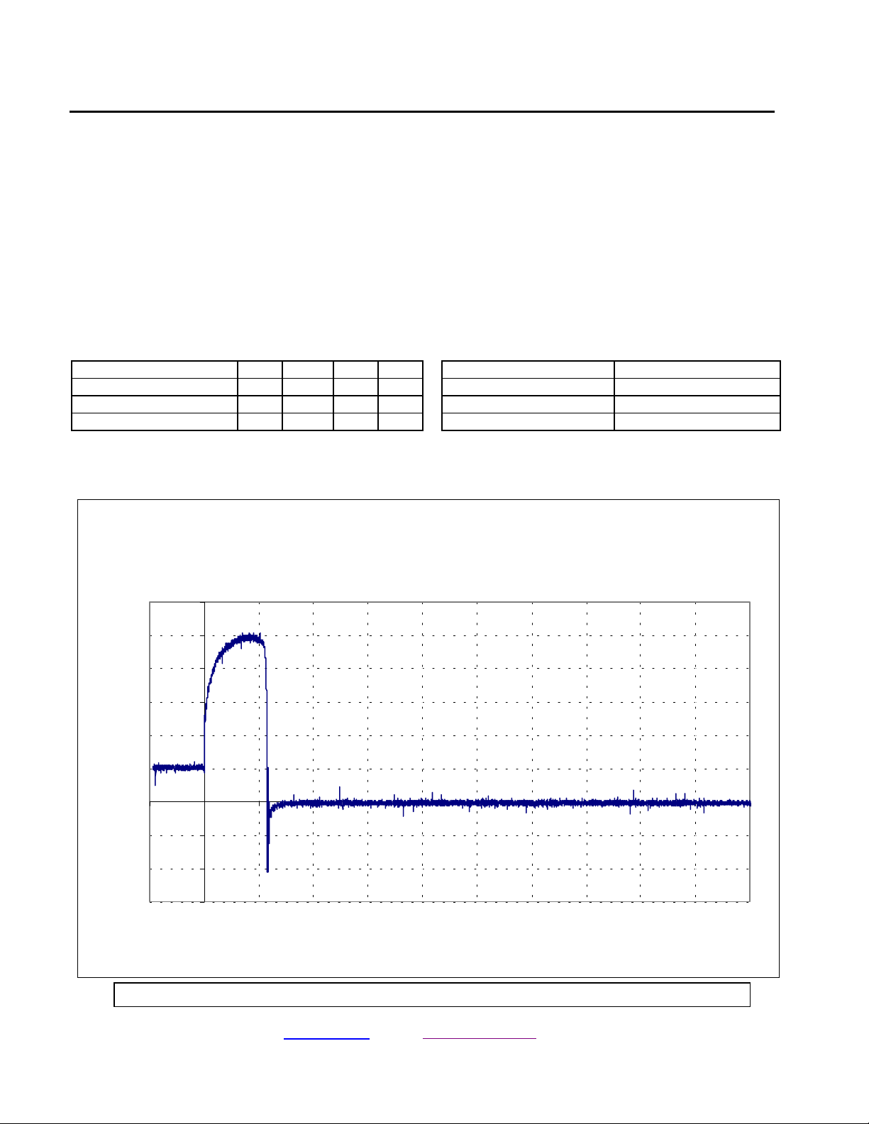
Typical Waveform
53248-102 Short Circuit Protection: Short-while-On @ 25°C
60
50
40
30
20
10
0
Output Load Current, A
-10
-20
-30
-200 0 200 400 600 800 1000 1200 1400 1600 1800 2000
Time, microseconds
Micropac Industries cannot assume any responsibility for any circuits shown or represent that they are free from patent infringement.
Micropac reserves the right to make changes at any time in order to improve design and to supply the best product possible.
MICROPAC INDUSTRIES, INC. HYBRID MICROELECTRONICS PRODUCTS DIVISION • 905 E. Walnut St., Garland, TX 75040 • (972) 272-3571 • Fax (972) 494-2281
www.micropac.com E-MAIL: [email protected]
05/16/01
Page 5

PRELIMINARY DATA SHEET
53248-102
28VDC SOLID STATE POWER CONTROLLER
APPLICATION INFORMATION
The cable harness occupies an important position in the total network to be protected. The wide variety and in
some cases considerable length and packing density used makes them particularly susceptible to persistent
overloads and/or overheating. The maximum current carrying capacity of a cable depends on its resistance, type
of insulation material and the ambient temperature. A cable, including insulation, generally consists of at least two
materials with different thermal capacitance and thermal resistance. The maximum temperatures of most cables
are at least +150°C (depending on the insulation properties) which is very close to the maximum junction
temperature of the SSPC (Shutdown). Since under overcurrent or short circuit conditions, the unit resistance per
unit length for the cable is much less than the R
less. Under these conditions, it is apparent that the SSPC can adequately protect properly selected cabling.
The following formulas provide methods for calculating the primary parameters.
Trip Current
of the SSPC, the unit heating of the cable will also be much
DS
I
= {(T
trip
T
= Maximum Trip Temperature
j max
T
= Ambient Temperature
a
j max
– Ta)/[R
θja
][R
ON (Tj max)
1/2
]}
R
= Thermal Resistance, Junction to Ambient
θja
R
ON
(Tj max)
= On-state resistance at Trip Temperature
On-state Resistance
25
0.006 (T – 25)
x e
R
R
(T) = R
on
= on-state resistance at 25°C
25
e = 2.718282 (natural logarithm)
T = T
at temperature of interest in °C
j
With the above information, the temperature and current trip can be determined based upon the type of mounting
chosen and the ambient temperatures of operation.
Precaution
When a short circuit causes turn-off of the SSPC, precautions must be taken to limit transient voltages generated by
any inductance in the load to less than the max voltage blocking of the SSPC (i.e. 63V). External protection is
recommended, either across the switch or across the load, to limit voltage transients to levels less than 63V to insure
the SSPC maximum blocking voltage is not exceeded.
Isolation of Control and Status
The SSPC was designed to utilize optical isolation both on the input/control and the status feed back. The only input
power required is that necessary to drive a control LED and provide pull up power for the open collector status
transistor. The SSPC derives its energy for operation from the 28 VDC load supply. As a result, the power in and
power out are completely isolated.
Micropac Industries cannot assume any responsibility for any circuits shown or represent that they are free from patent infringement.
Micropac reserves the right to make changes at any time in order to improve design and to supply the best product possible.
MICROPAC INDUSTRIES, INC. HYBRID MICROELECTRONICS PRODUCTS DIVISION • 905 E. Walnut St., Garland, TX 75040 • (972) 272-3571 • Fax (972) 494-2281
www.micropac.com E-MAIL: [email protected]
05/16/01
Page 6
PRELIMINARY DATA SHEET
53248-102
28VDC SOLID STATE POWER CONTROLLER
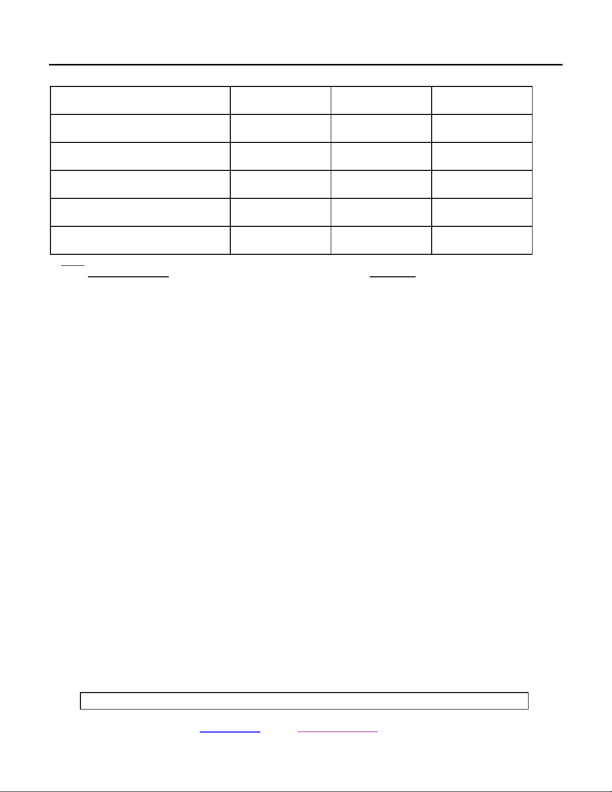
Truth Table
Control Output Status
Normal Operation L
H
Current Overload L
H
Over-Temperature L
H
Undervoltage L
H
Overvoltage L
H
L
H
L
L
L
L
L
L
L
L
H
L
H
H
H
H
H
H
H
H
Note:
For Control Output: For Status
L = “Low” Level Voltage H = Open Collector
H = “High” Level Voltage L = Current Sink
Loads
The 53248-102 SSPC is designed to handle low side loads from +5 VDC
to +40 VDC. Combinations of inductive,
resistive and capacitive may be used. This includes lamps and DC motors.
Inductive loads require protecting the SSPC from voltage transients as pointed out in the precaution section above.
For capacitive loads, the user must assure that junction temperature of the body is not exceeded. If at turn off, the V
drops below the voltage charge on the capacitor, current can flow through the body diode of the FET switch with no
inherent capability to limit this spike of reverse current. Incandescent lamps must be treated much like capacitive
loads in that in-rush currents at turn-on can cause an overcurrent condition.
CC
DC motors must be treated like capacitive loads because in-rush currents can be very high. Should a machine
continue to rotate after power is removed, reverse currents due to back EMF need to be addressed.
Heatsinking
The SSPC is designed to take advantage of the relationship between junction temperatures and heat sink thermal
impedance. As described in the section discussing current trip characteristics, the thermal impedance of the heat sink
utilized can determine the magnitude and time of over current or short circuit current expected in a system.
Offset voltage
The Power MOSFETs used in Micropac’s SSPC have very low on resistance and therefore low power dissipation.
Typical on-state resistance at 25°C is only 38 mΩ. Due to internal design the typical V
relatively constant until the current reaches approximately 2 amperes when V
is 60 mV. For higher currents, the R
DS
at 0.5 A is 50 mV. This stays
DS
is constant at Tj of +25°C. Maximum RDS at +150°C is 80 mΩ.
Since the design of SSPC current limit is temperature dependent, there is no need for a current sensing resistor and
therefore no additional voltage drop which would add to the R
Micropac Industries cannot assume any responsibility for any circuits shown or represent that they are free from patent infringement.
Micropac reserves the right to make changes at any time in order to improve design and to supply the best product possible.
MICROPAC INDUSTRIES, INC. HYBRID MICROELECTRONICS PRODUCTS DIVISION • 905 E. Walnut St., Garland, TX 75040 • (972) 272-3571 • Fax (972) 494-2281
www.micropac.com E-MAIL: [email protected]
DS
.
05/16/01
DS
 Loading...