

Page 1
PC123XNNSZ0F
Series
PC123XNNSZ0F Series
DIP 4pin Reinforced Insulation Type
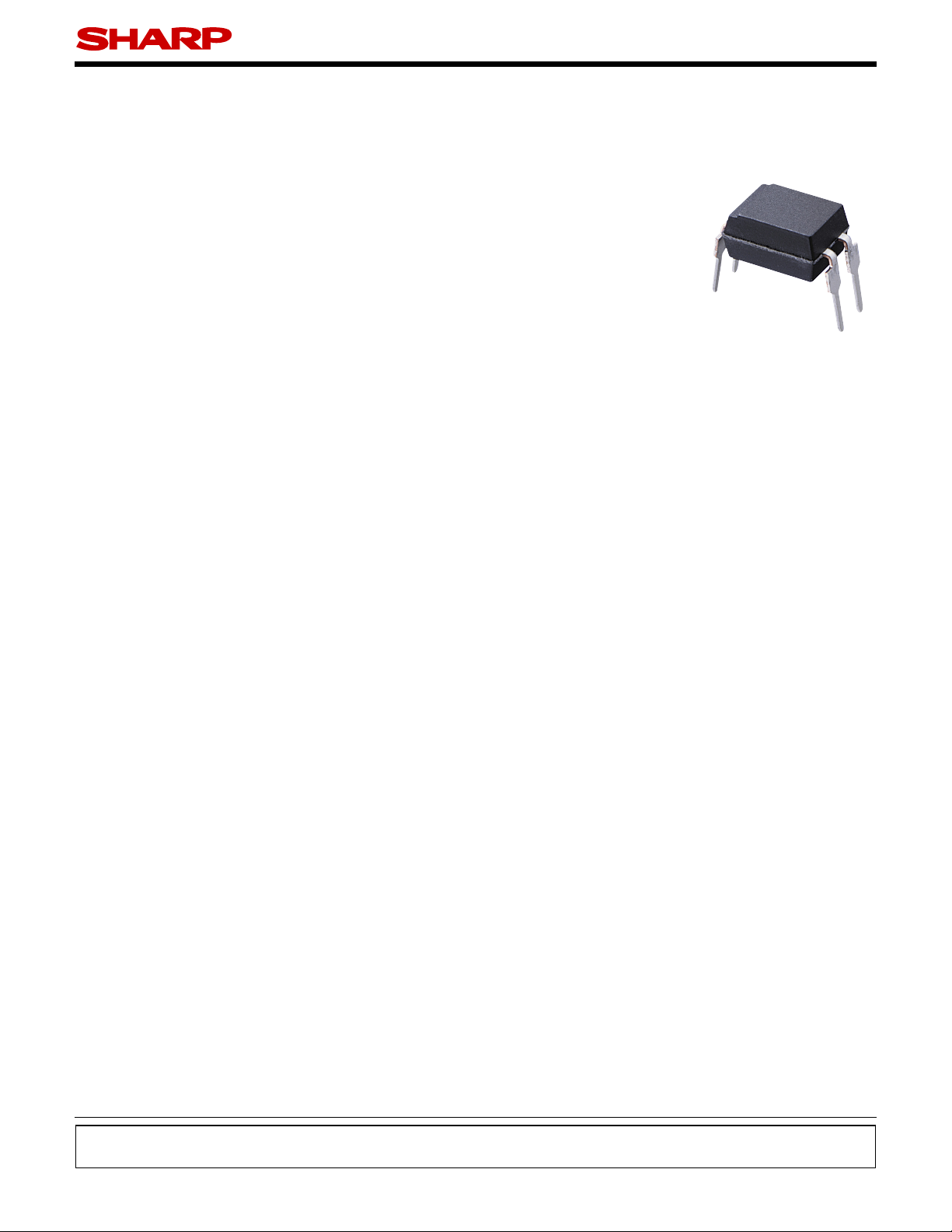
Photocoupler
Description
■
PC123XNNSZ0F Series
coupled to a phototransistor.
It is packaged in a 4-pin DIP, available in wide-lead
spacing option and SMT gullwing lead-form option.
Input-output isolation voltage(rms) is 5kV.
CTR is 50% to 400% at input current of 5mA
Features
■
1. 4-pin DIP package
2. Double transfer mold package (Ideal for Flow Soldering)
3. Current transfer ratio (CTR : MIN. 50% at I
V
5V)
=
CE
4. Several CTR ranks available
5. Reinforced insulation type (Isolation distance : MIN.
0.4mm)
6. Long creepage distance type (wide lead-form type
only : MIN. 8mm)
7. High isolation voltage between input and output
(V
(rms) : 5kV)
iso
8. Lead-free and RoHS directive compliant
contains an IRED optically
5 mA,
=
F
Agency approvals/Compliance
■
1. Recognized by UL1577 (Double protection isolation),
fi le No. E64380 (as model No.
2. Approved by BSI, BS-EN60065, file No. 7087, BS-
EN60950 fi le No. 7409, (as model No.
3. Approved by SEMKO, EN60065, EN60950, (as model No.
PC123
4. Approved by DEMKO, EN60065, EN60950, (as model No.
PC123
5. Approved by NEMKO, EN60065, EN60950, (as model No.
PC123
6. Approved by FIMKO, EN60065, EN60950, (as model
No.
PC123
7. Recognized by CSA fi le No. CA95323, (as model No.
PC123
8. Approved by VDE, DIN EN60747-5-2(
tion), fi le No. 40008087 (as model No.
9. Package resin : UL fl ammability grade (94V - 0)
(∗) DIN EN60747-5-2 : successor standard of DIN VDE0884.
Applications
■
1. I/O isolation for MCUs (Micro Controller Units)
2. Noise suppression in switching circuits
3. Signal transmission between circuits of different potentials and impedances
4. Over voltage detection
)
)
)
)
)
PC123
)
PC123
∗
) (as an op-
PC123
)
)
Notice The content of data sheet is subject to change without prior notice.
In the absence of confi rmation by device specifi cation sheets, SHARP takes no responsibility for any defects that may occur in equipment using any SHARP
devices shown in catalogs, data books, etc. Contact SHARP in order to obtain the latest device specifi cation sheets before using any SHARP device.
1
Sheet No.: D2-A09501EN
© SHARP Corporation
Date Sep. 1. 2006
Page 2
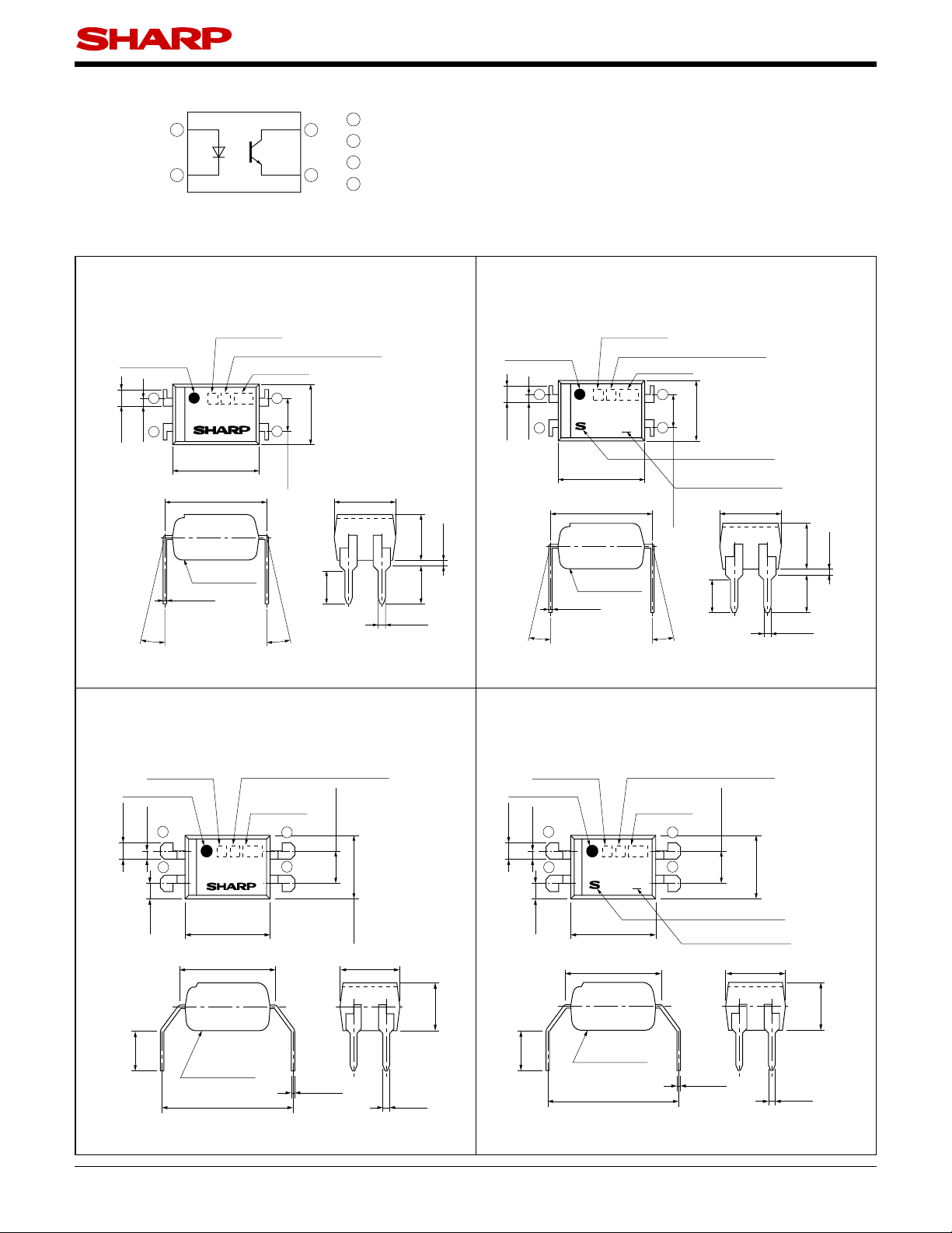
Internal Connection Diagram
■
1
2
PC123XNNSZ0F Series
1
4
3
Anode
2
Cathode
3
Emitter
4
Collector
Outline Dimensions
■
1. Through-Hole [ex.
Rank mark
Anode mark
1
±0.3
±0.2
2
1.2
0.6
0.26
θ
θ : 0 to 13˚
Product mass : approx. 0.23g
Factory identification mark
PC123
±0.3
6.5
±0.30
7.62
Epoxy resin
±0.10
PC123XNNSZ0F
Date code
4
±0.30
3
4.58
±0.25
2.54
±0.5
θ
2.7
4.58
±0.30
0.5
(Unit : mm)
]
±0.5
TYP.
3.5
0.5
±0.5
3.0
±0.1
2. Through-Hole (VDE option)
[ex.
PC123XNYSZ0F
Anode mark
1
±0.3
±0.2
2
1.2
0.6
θ
PC123
6.5
7.62
Epoxy resin
±0.10
0.26
θ : 0 to 13˚
Rank mark
Factory identification mark
4
±0.3
±0.30
]
Date code
4
±0.30
3
4.58
SHARP mark "S"
VDE idenfication mark
±0.25
2.54
±0.5
2.7
θ
4.58
±0.30
0.5
±0.5
±0.5
±0.1
3.5
3.0
TYP.
0.5
Product mass : approx. 0.23g
3. Wide Through-Hole Lead-Form
[ex.
PC123XNNFZ0F
Anode mark
±0.3
±0.2
1.2
0.6
Rank mark
1
2
PC123
]
Factory identification mark
Date code
±0.25
4
3
2.54
4.
Wide Through-Hole Lead-Form (VDE option)
[ex.
PC123XNYFZ0F
Rank mark
Factory identification mark
Anode mark
PC123
Date code
4
3
±0.3
±0.2
1
1.2
0.6
2
4
MIN.
2.7
±0.1
1.0
6.5
7.62
±0.3
±0.30
±0.30
4.58
4.58
±0.30
±0.5
3.5
Epoxy resin
±0.50
10.16
0.26
±0.10
0.5
±0.1
MIN.
2.7
±0.1
1.0
6.5
±0.3
7.62
±0.30
Epoxy resin
±0.50
10.16
Product mass : approx. 0.23g Product mass : approx. 0.23g
]
±0.25
2.54
±0.30
4.58
SHARP mark "S"
VDE idenfication mark
±0.30
4.58
±0.10
0.26
0.5
±0.5
3.5
±0.1
2
Sheet No.: D2-A09501EN
Page 3
PC123XNNSZ0F Series
(Unit : mm)
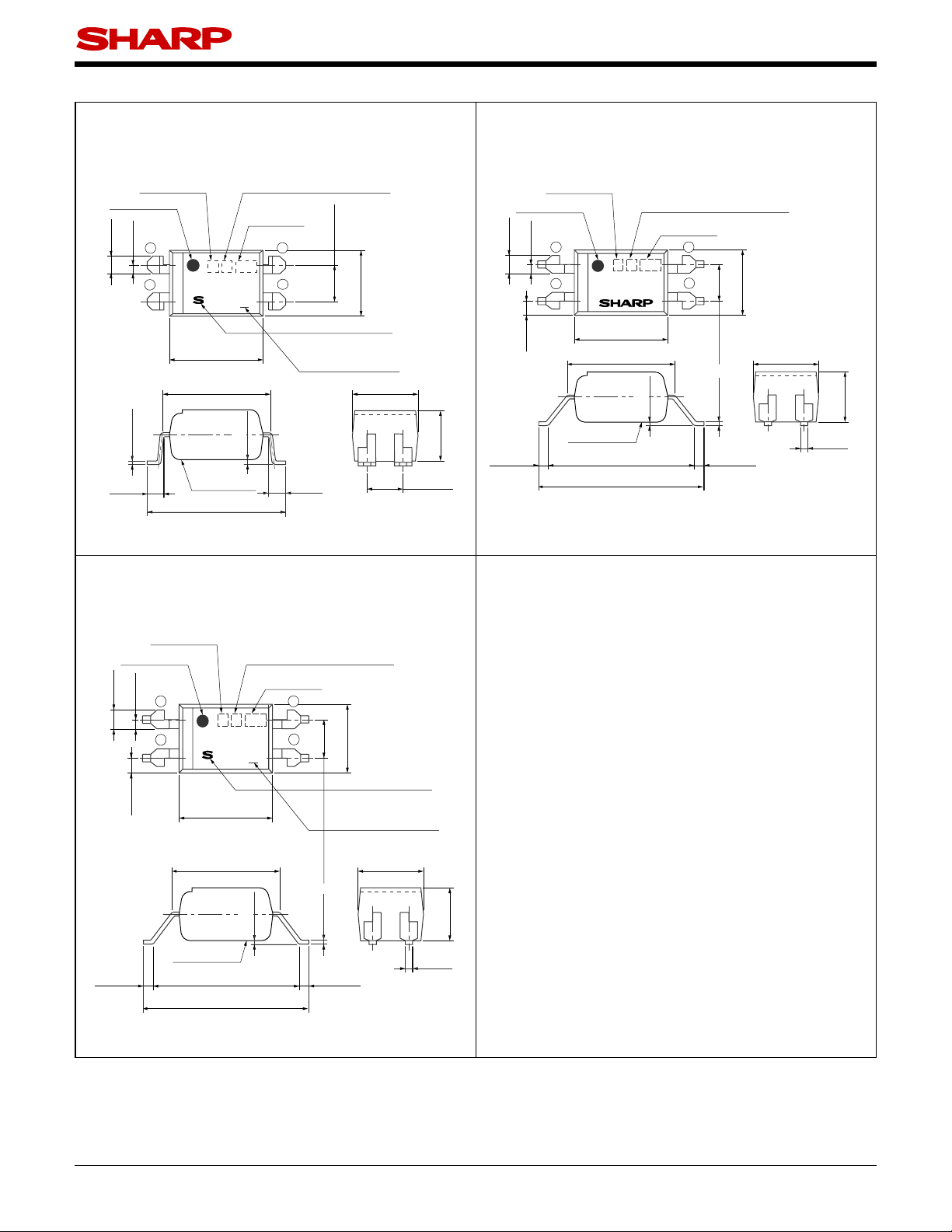
5. SMT Gullwing Lead-Form (VDE option)
[ex.
PC123XNYIP0F
Rank mark
Anode mark
±0.3
±0.2
1.2
1
0.6
2
PC123
±0.3
6.5
±0.30
7.62
±0.10
0.26
1.0
+0.4
−0.0
Epoxy resin
+0.0
10.0
−0.5
Product mass : approx. 0.22g
]
Factory identification mark
Date code
4
±0.25
0.35
±0.25
4
3
2.54
SHARP mark "S"
VDE
idenfication mark
+0.4
1.0
−0.0
±0.30
4.58
4.58
±0.30
2.54
±0.5
3.5
±0.25
6. Wide SMT Gullwing Lead-Form
[ex.
PC123XNNUP0F
Rank mark
Anode mark
±0.3
±0.2
1.2
1
0.6
2
PC123
±0.1
1.0
6.5
7.62
±0.3
±0.30
±0.25
Epoxy resin
0.75
±0.25
10.16
12
±0.50
MAX
Product mass : approx. 0.22g
]
Factory identification mark
Date code
4
±0.25
2.54
±0.10
0.26
0.75
±0.30
4.58
±0.25
3
0.25
4.58
±0.30
0.5
±0.5
3.5
±0.1
7.
Wide SMT Gullwing Lead-Form (VDE option)
[ex.
PC123XNYUP0F
]
Rank mark
Anode mark
±0.3
±0.2
1.2
0.6
±0.1
1.0
1
2
Factory identification mark
Date code
4
PC123
3
4
±0.3
6.5
±0.30
7.62
±0.30
4.58
SHARP mark "S"
VDE
idenfication mark
±0.25
4.58
±0.30
2.54
±0.25
0.25
±0.10
0.26
Epoxy resin
0.75
±0.25
10.16
12
±0.50
MAX
0.75
±0.25
0.5
±0.5
3.5
±0.1
Product mass : approx. 0.22g
3
Sheet No.: D2-A09501EN
Page 4
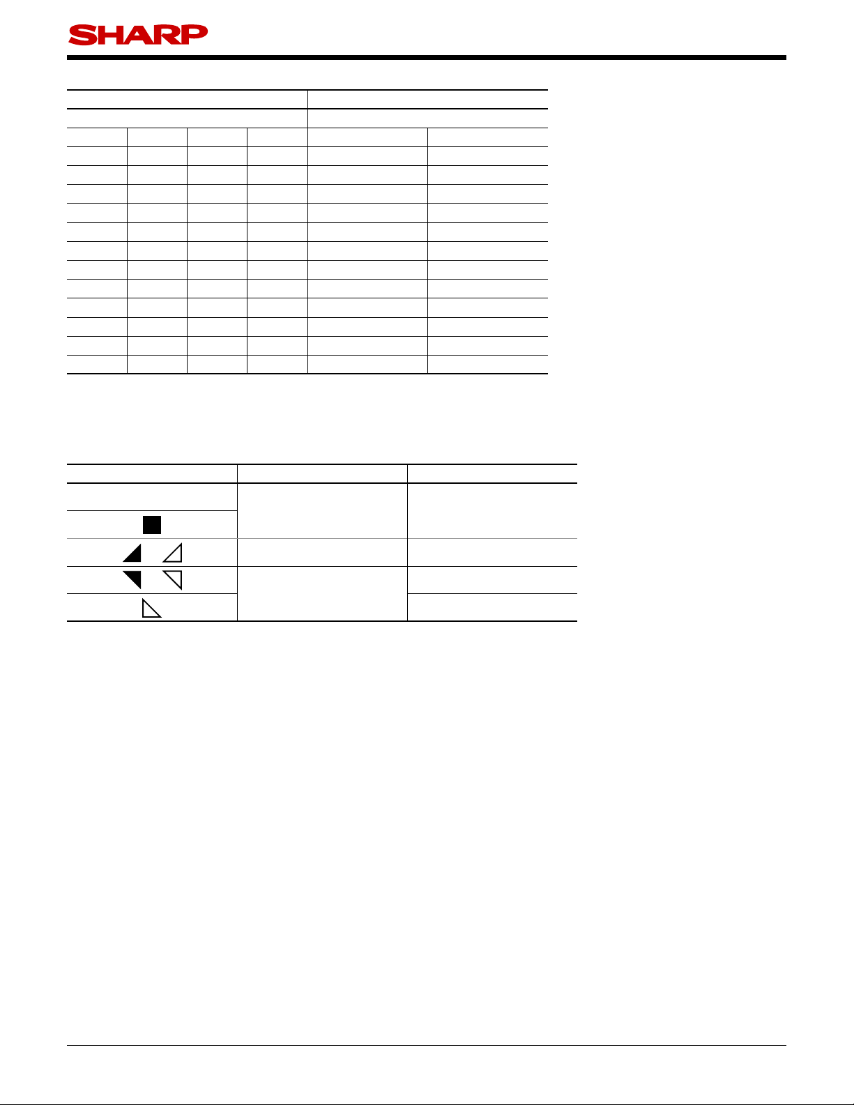
Date code (2 digit)
1st digit 2nd digit
Year of production Month of production
A.D. Mark A.D. Mark Month Mark
1990 A 2002 P January 1
1991 B 2003 R February 2
1992 C 2004 S March 3
1993 D 2005 T April 4
1994 E 2006 U May 5
1995 F 2007 V June 6
1996 H 2008 W July 7
1997 J 2009 X August 8
1998 K 2010 A September 9
1999 L 2011 B October O
2000 M 2012 C November N
2001 N : : December D
repeats in a 20 year cycle
PC123XNNSZ0F Series
Factory identifi cation mark and Plating material
Factory identifi cation Mark Country of origin Plating material
no mark
Japan SnCu (Cu : TYP. 2%)
or Indonesia SnBi (Bi : TYP. 2%)
or
SnCu (Cu : TYP. 2%)*
China
SnCu (Cu : TYP. 2%)
* Up to Date code "T4" (April 2005), SnBi (Bi : TYP. 2%).
** This factory marking is for identifi cation purpose only.
Please contact the local SHARP sales representative to see the actural status of the production.
Rank mark
Refer to the Model Line-up table.
4
Sheet No.: D2-A09501EN
Page 5
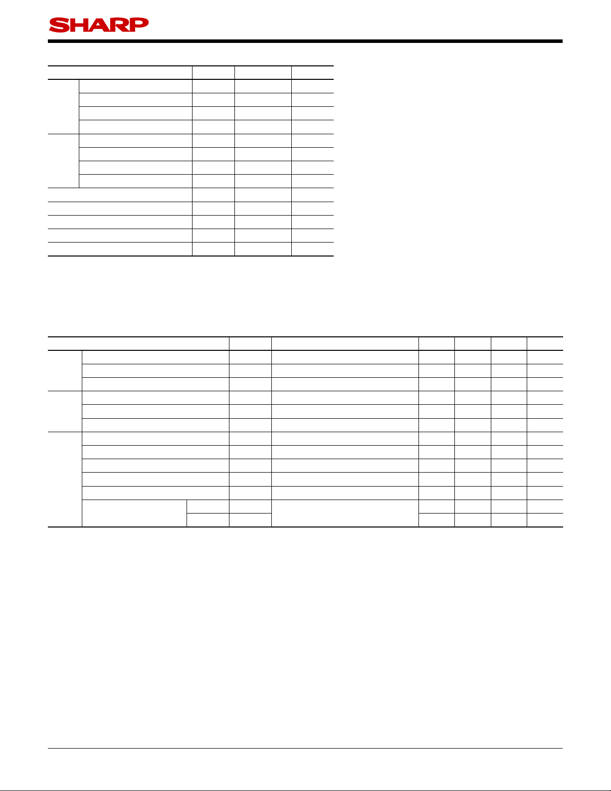
Absolute Maximum Ratings
■
Parameter Symbol Rating Unit
Forward current I
*1
Input
Peak forward current I
Reverse voltage V
Power dissipation P 70 mW
Collector-emitter voltage V
Output
Emitter-collector voltage V
Collector current I
Collector power dissipation
Total power dissipation P
*2
Isolation voltage V
Operating temperature T
Storage temperature T
*2
Soldering temperature T
*1 Pulse width≤100ms, Duty ratio : 0.001
*2 40 to 60%RH, AC for 1 minute, f = 60Hz
*3 For 10s
(T
F
FM
R
CEO
ECO
C
P
C
tot
(rms) 5 kV
iso
opr
stg
sol
50 mA
1A
6V
70 V
6V
50 mA
150 mW
200 mW
30 to +100 C
−
55 to +125 C
−
260 C
=
a
PC123XNNSZ0F Series
25C)
Electro-optical Characteristics
■
Parameter Symbol Condition MIN. TYP. MAX. Unit
Forward voltage V
Input
Reverse current I
Terminal capacitance C
Collector dark current I
Output
Collector-emitter breakdown voltage
Emitter-collector breakdown voltage
Collector current I
Collector-emitter saturation voltage V
Transfer
charac
teristics
Isolation resistance R
Floating capacitance C
−
Cut-off frequency f
Response time
Rise time
Fall time
BV
BV
F
R
t
CEO
CEO
ECO
C
CE(sat)
ISO
f
C
t
r
t
f
20mA
I
=
F
4V
V
=
R
V=0, f=1kHz
V
I
C
I
E
I
=
F
20mA, I
I
=
F
50V, I
=
CE
0.1mA, I
=
=10μ
5mA, V
0
=
F
0 70
=
F
A, I
0 6
=
F
5V 2.5
=
CE
1mA
=
C
DC500V, 40 to 60%RH 5×10101×10
V=0, f=1MHz
5V, I
V
=
CE
V
2mA, R
=
C
2V, I
=
CE
=
C
=
L
2mA, R
100Ω, −3dB
100
=
Ω
L
−
1.2 1.4 V
−−
−
30 250 pF
−−
−−
−−
−
−
−
−
−
−
0.1 0.2 V
11
0.6 1 pF
80
418μs
318μs
25C)
(T
=
a
10
A
μ
100 nA
V
nA
20 mA
−Ω
−
kHz
5
Sheet No.: D2-A09501EN
Page 6
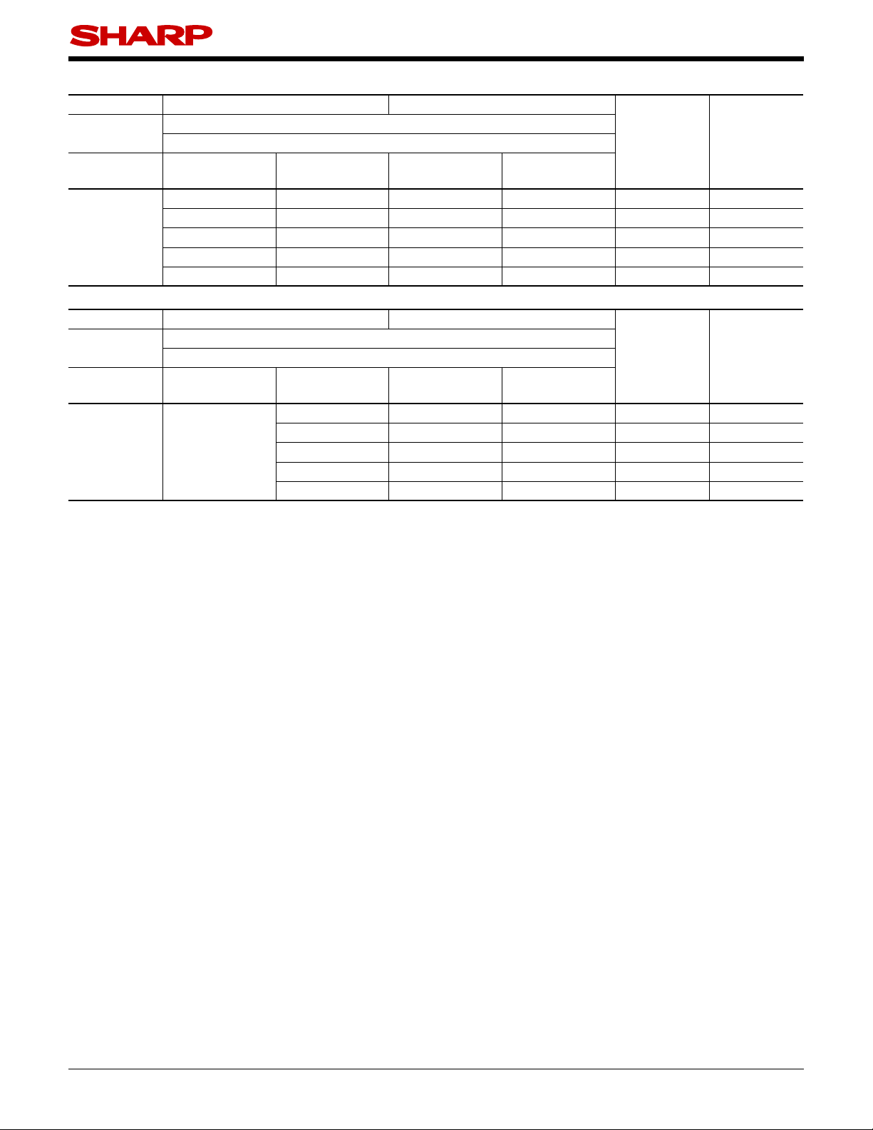
Model Line-up
■
Lead Form Through-Hole Wide Through-Hole
Package
DIN
EN60747-5-2
−
Approved
Sleeve
100pcs/sleeve
−
PC123XNNSZ0F PC123XNYSZ0F PC123XNNFZ0F PC123XNYFZ0F
PC123X1NSZ0F PC123X1YSZ0F PC123X1NFZ0F PC123X1YFZ0F
Model No.
PC123X2NSZ0F PC123X2YSZ0F PC123X2NFZ0F PC123X2YFZ0F
PC123X5NSZ0F PC123X5YSZ0F PC123X5NFZ0F PC123X5YFZ0F
PC123X8NSZ0F PC123X8YSZ0F PC123X8NFZ0F PC123X8YFZ0F
Approved
PC123XNNSZ0F Series
[mA]
I
C
5mA,
(I
=
T
V
F
CE
25˚C)
=
a
5V,
=
Rank mark
With or without 2.5 to 20
L 2.5 to 7.5
M 5 to 12.5
N 10 to 20
E 5 to 10
Lead Form SMT Gullwing Wide SMT Gullwing
Package
DIN
EN60747-5-2
−
Approved
Taping
2 000pcs/reel
−
Approved
PC123XNYIP0F PC123XNNUP0F PC123XNYUP0F
PC123X1YIP0F PC123X1NUP0F PC123X1YUP0F
Model No.
−
PC123X2YIP0F PC123X2NUP0F PC123X2YUP0F
PC123X5YIP0F PC123X5NUP0F PC123X5YUP0F
PC123X8YIP0F PC123X8NUP0F PC123X8YUP0F
Please contact a local SHARP sales representative to inquire about production status.
[mA]
I
C
5mA,
(I
=
T
V
F
CE
25˚C)
=
a
5V,
=
Rank mark
With or without 2.5 to 20
L 2.5 to 7.5
M 5 to 12.5
N 10 to 20
E 5 to 10
6
Sheet No.: D2-A09501EN
Page 7
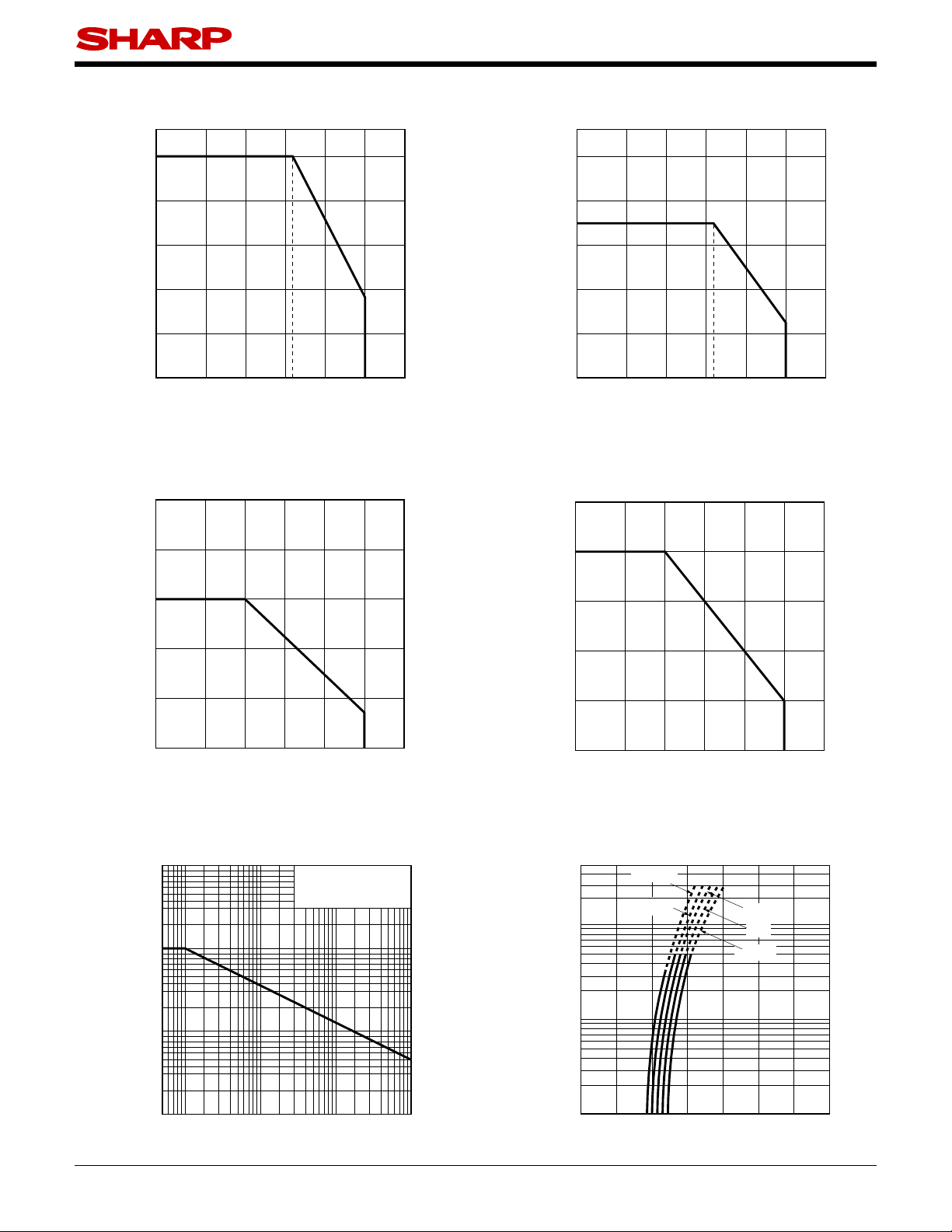
PC123XNNSZ0F Series
Fig.1 Forward Current vs. Ambient
Temperature
50
40
(mA)
F
30
20
Forward current I
10
0
−30 0 25 50 55 75 100 125
Ambient temperature Ta (˚C)
Fig.3 Collector Power Dissipation vs.
Ambient Temperature
250
Fig.2 Diode Power Dissipation vs.
Ambient Temperature
100
80
70
60
40
Diode power dissipation P (mW)
20
0
−30 0 25 50 55 75 100 125
Ambient temperature Ta (˚C)
Fig.4 Total Power Dissipation vs. Ambient
Temperature
250
200
(mW)
C
150
100
50
Collector power dissipation P
0
−30 0 25 50 75 100 125
Ambient temperature Ta (˚C)
200
(mW)
tot
150
100
50
Total Power dissipation P
0
−30 0 25 50 75 100
Ambient temperature Ta (˚C)
125
Fig.5 Peak Forward Current vs. Duty Ratio Fig.6 Forward Current vs. Forward Voltage
10 000
(mA)
1 000
FM
Pulse width≤100μs
T
=25˚C
a
(mA)
F
100
T
=75˚C
a
50˚C
25˚C
0˚C
−25˚C
100
Peak forward current I
10
−3
10
−2
10
Duty ratio
10
Forward current I
−1
10
1
1
0 0.5 1 1.5 2 2.5 3 3.5
Forward voltage VF (V)
Sheet No.: D2-A09501EN
7
Page 8
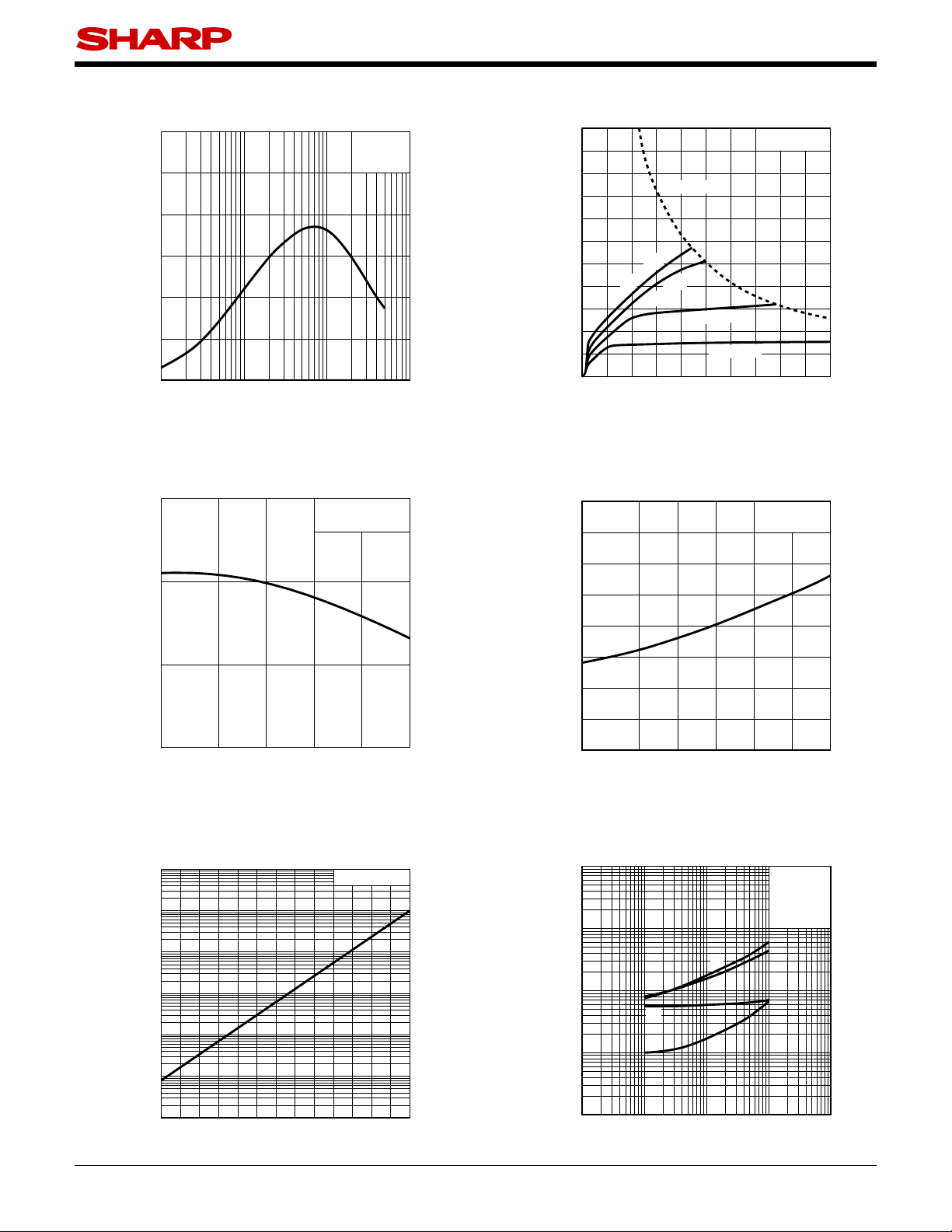
PC123XNNSZ0F Series
Fig.7 Current Transfer Ratio vs.
Forward Current
300
250
200
150
100
Current transfer ratio CTR (%)
50
0
0.1 1 10 100
Forward current IF (mA)
V
T
=5V
CE
=25˚C
a
Fig.9 Relative Current Transfer Ratio vs.
Ambient Temperature
150
100
I
=5mA
F
VCE=5V
Fig.8 Collector Current vs.
Collector-emitter Voltage
60
54
PC (MAX.)
(mA)
C
48
42
36
30
24
18
Collector current I
12
6
=30mA
F
I
=20mA
F
I
=10mA
I
F
5mA
=
I
F
0
012345678910
Collector-emitter voltage VCE (V)
Fig.10
Collector - emitter Saturation Voltage
vs. Ambient Temperature
0.16
(V)
0.14
CE (sat)
0.12
0.1
=25˚C
T
a
I
=20mA
F
IC=1mA
50
Relative current transfer ratio (%)
0
−30
0 255075100
Ambient temperature T
(˚C)
a
Fig.11 Collector Dark Current vs.
Ambient Temperature
−5
10
−6
10
(A)
−7
CEO
10
−8
10
−9
10
Collector dark current I
−10
10
VCE=50V
0.08
0.06
0.04
0.02
Collector-emitter saturation voltage V
0
−30 0 20406080100
Ambient temperature Ta (˚C)
Fig.12 Response Time vs.
Load Resistance
1 000
100
t
10
t
d
Response time (μs)
1
t
s
t
V
=2V
CE
IC=2mA
Ta=25˚C
r
f
−11
10
−30 0 20406080100
Ambient temperature Ta (˚C)
0.1
0.01 0.1 1 10 100
Load resistance (kΩ)
Sheet No.: D2-A09501EN
8
Page 9
PC123XNNSZ0F Series
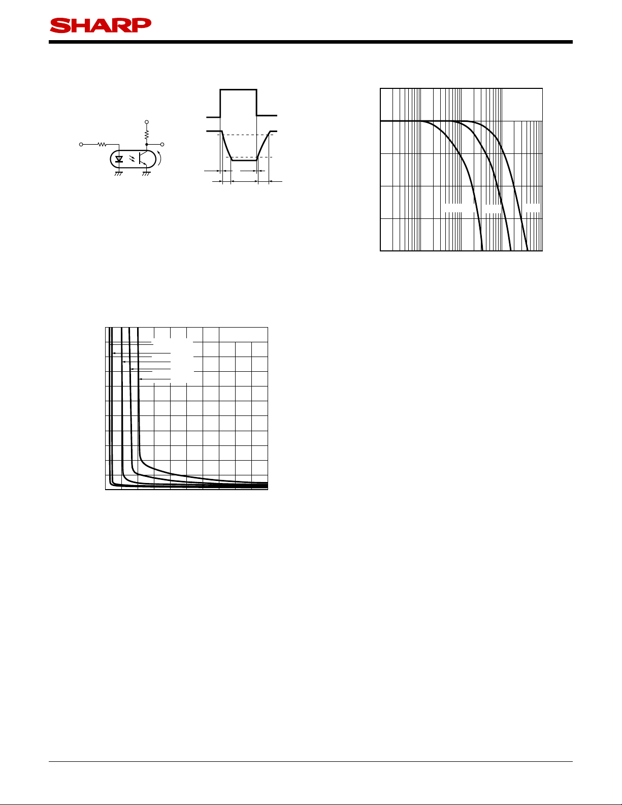
Fig.13 Test Circuit for Response Time Fig.14 Frequency Response
Input
Output
10%
CE
t
d
t
s
t
r
90%
t
f
Input
V
CC
Output
R
R
D
L
V
Please refer to the conditions in Fig.12.
Fig.15 Collector-emitter Saturation Voltage vs.
Forward Current
=25˚C
T
5
(V)
CE (sat)
4.5
4
3.5
I
=0.5mA
C
1mA
3mA
5mA
7mA
3
2.5
2
1.5
1
0.5
Collector-emitter saturation voltage V
0
0 2 4 6 8 101214161820
Forward current IF (mA)
a
5
0
(dB)
v
−5
−10
Voltage gain A
R
L
=10kΩ
−15
−20
0.1 10 100
1
Frequency (kHz)
1kΩ
V
=5V
CE
=2mA
I
C
Ta=25˚C
100Ω
1 000
Remarks : Please be aware that all data in the graph are just for reference and not for guarantee.
9
Sheet No.: D2-A09501EN
Page 10
Design Considerations
■
●
Design guide
While operating at IF<1mA, CTR variation may increase.
Please make design considering this fact.
This product is not designed against irradiation and incorporates non-coherent IRED.
●
Degradation
In general, the emission of the IRED used in photocouplers will degrade over time.
In the case of long term operation, please take the general IRED degradation (50% degradation over 5
years) into the design consideration.
●
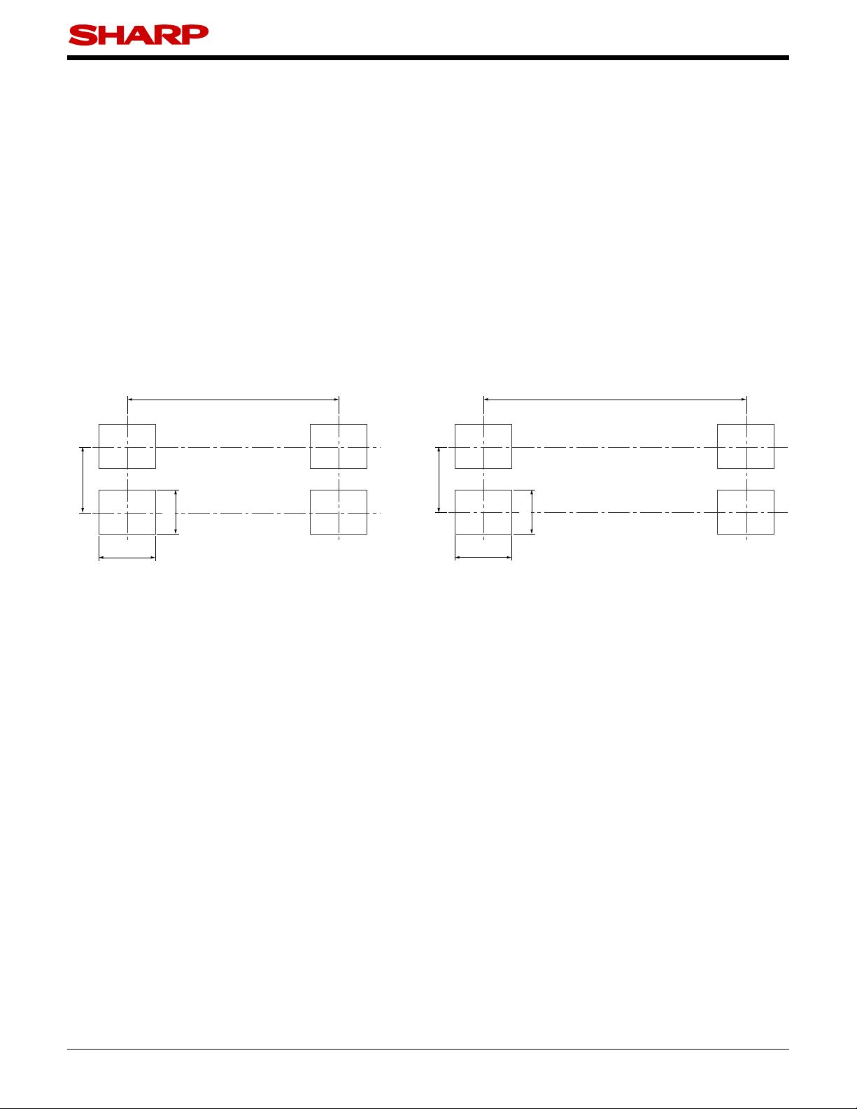
Recommended foot print (reference)
SMT Gullwing lead-form Wide SMT Gullwing lead-form
8.2
10.2
PC123XNNSZ0F Series
2.54
2.2
1.7
2.54
1.7
2.2
(Unit : mm)
For additional design assistance, please review our corresponding Optoelectronic Application Notes.
✩
10
Sheet No.: D2-A09501EN
Page 11
Manufacturing Guidelines
■
●
Soldering Method
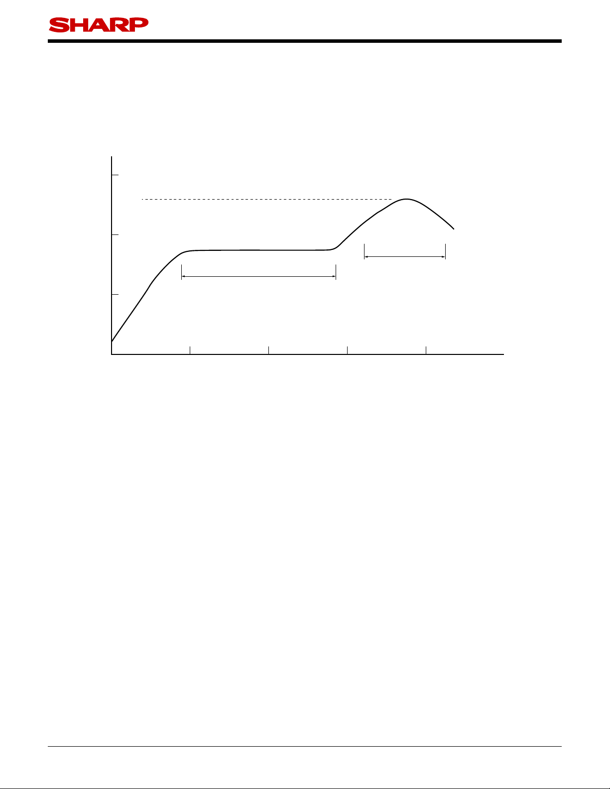
Refl ow Soldering :
Refl ow soldering should follow the temperature profi le shown below.
Soldering should not exceed the curve of temperature profi le and time.
Please don't solder more than twice.
(˚C)
PC123XNNSZ0F Series
300
200
100
0
0
Terminal : 260˚C peak
(package surface : 250˚C peak)
Reflow
220˚C or more, 60s or less
Preheat
150 to 180˚C, 120s or less
1234
(min)
Flow Soldering :
Due to SHARP's double transfer mold construction submersion in fl ow solder bath is allowed under the be-
low listed guidelines.
Flow soldering should be completed below 270C and within 10s.
Preheating is within the bounds of 100 to 150C and 30 to 80s.
Please don't solder more than twice.
Hand soldering
Hand soldering should be completed within 3s when the point of solder iron is below 400C.
Please don't solder more than twice
Other notice
Please test the soldering method in actual condition and make sure the soldering works fi ne, since the im-
pact on the junction between the device and PCB varies depending on the tooling and soldering conditions.
11
Sheet No.: D2-A09501EN
Page 12

PC123XNNSZ0F Series
●
Cleaning instructions
Solvent cleaning :
Solvent temperature should be 45˚C or below. Immersion time should be 3 minutes or less.
Ultrasonic cleaning :
The impact on the device varies depending on the size of the cleaning bath, ultrasonic output, cleaning time,
size of PCB and mounting method of the device.
Therefore, please make sure the device withstands the ultrasonic cleaning in actual conditions in advance of
mass production.
Recommended solvent materials :
Ethyl alcohol, Methyl alcohol and Isopropyl alcohol.
In case the other type of solvent materials are intended to be used, please make sure they work fi ne in ac-
tual using conditions since some materials may erode the packaging resin.
●
Presence of ODC
This product shall not contain the following materials.
And they are not used in the production process for this product.
Regulation substances : CFCs, Halon, Carbon tetrachloride, 1.1.1-Trichloroethane (Methylchloroform)
Specifi c brominated fl ame retardants such as the PBB and PBDE are not used in this product at all.
This product shall not contain the following materials banned in the RoHS Directive (2002/95/EC).
•Lead, Mercury, Cadmium, Hexavalent chromium, Polybrominated biphenyls (PBB), Polybrominated
diphenyl ethers (PBDE).
12
Sheet No.: D2-A09501EN
Page 13

Package specifi cation
■
●
Sleeve package
1. Through-Hole
Package materials
Sleeve : HIPS (with anti-static material)
Stopper : Styrene-Elastomer
Package method
MAX. 100pcs of products shall be packaged in a sleeve. Both ends shall be closed by tabbed and tabless
stoppers.
The product shall be arranged in the sleeve with its anode mark on the tabless stopper side.
MAX. 20 sleeves in one case.
Sleeve outline dimensions
12
PC123XNNSZ0F Series
±2
520
10.8
5.8
6.7
2. Wide Through-Hole
Package materials
Sleeve : HIPS (with anti-static material)
Stopper : Styrene-Elastomer
Package method
MAX. 100pcs of products shall be packaged in a sleeve. Both ends shall be closed by tabbed and tabless
stoppers.
The product shall be arranged in the sleeve with its anode mark on the tabless stopper side.
MAX. 20 sleeves in one case.
Sleeve outline dimensions
15
(Unit : mm)
±2
6.35
10.8
5.9
13
520
(Unit : mm)
Sheet No.: D2-A09501EN
Page 14
●
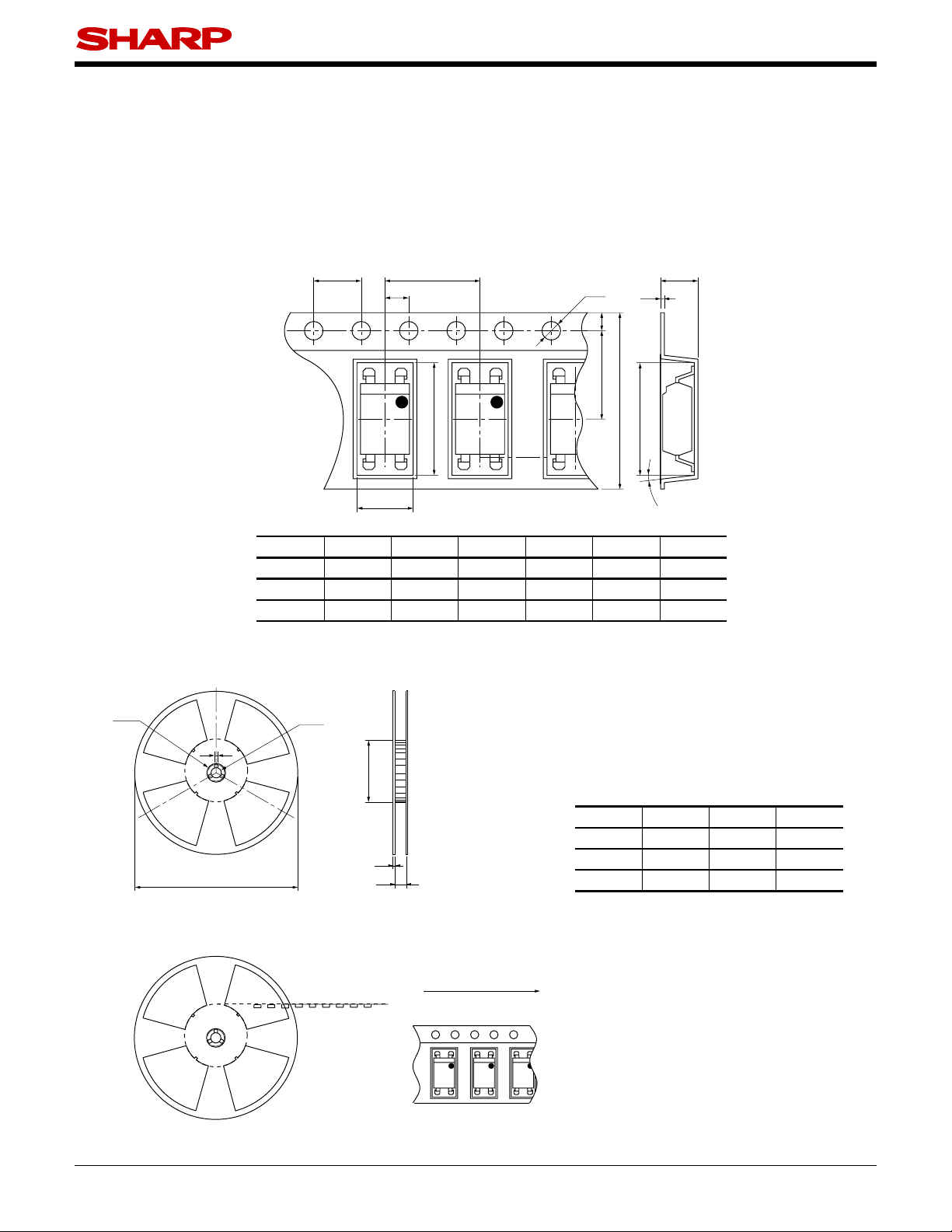
Tape and Reel package
1. SMT Gullwing
Package materials
Carrier tape : PS
Cover tape : PET (three layer system)
Reel : PS
Carrier tape structure and Dimensions
F
D J
E
H
G
C
B
PC123XNNSZ0F Series
I
A
H
Dimensions List (Unit : mm)
16.0
A
±0.3
B
7.5
H
±0.1
10.4
0.40
Reel structure and Dimensions
e
g
a
d
Direction of product insertion
±0.1
I
±0.05
c
4.0
a
e
MAX.
5˚
F
±0.1
G
φ1.5
−0.0
+0.1
(Unit : mm)
c
±1.5
f
±1
2.0
±0.5
φ100
g
2.0
±1
±0.5
φ13.0
d
±0.5
K
1.75
4.2
C
±0.10
J
±0.1
8.0
5.1
D
±0.1
2.0
E
±0.1
K
±0.1
Dimensions List
φ330b17.5
f
b
φ23
Pull-out direction
[Packing : 2 000pcs/reel]
14
Sheet No.: D2-A09501EN
Page 15

2. Wide SMT Gullwing
Package materials
Carrier tape : PS
Cover tape : PET (three layer system)
Reel : PS
Carrier tape structure and Dimensions
F D
PC123XNNSZ0F Series
G
E
C
B
J
I
Dimensions List
24.0
A
±0.3
B
11.5
H
±0.1
12.4
0.40
Reel structure and Dimensions
e
g
a
d
±0.1
I
±0.05
H
K
A
H
MAX.
5˚
(Unit : mm)
C
±0.10
1.75
J
±0.1
4.1
c
f
b
8.0
5.1
D
±0.1
2.0
E
±0.1
4.0
F
±0.1
φ1.5
−0.0
G
+0.1
K
±0.1
Dimensions List
a
φ330b25.5
φ23
e
±1
2.0
f
±0.5
±1.5
(Unit : mm)
c
±1
φ100
g
±0.5
2.0
φ13.0
d
±0.5
Direction of product insertion
Pull-out direction
[Packing : 2 000pcs/reel]
Sheet No.: D2-A09501EN
15
Page 16

Important Notices
■
· The circuit application examples in this publication
are provided to explain representative applications of
SHARP devices and are not intended to guarantee any
circuit design or license any intellectual property rights.
SHARP takes no responsibility for any problems related
to any intellectual property right of a third party resulting
from the use of SHARP's devices.
· Contact SHARP in order to obtain the latest device
specification sheets before using any SHARP device.
SHARP reserves the right to make changes in the
specifi cations, characteristics, data, materials, structure,
and other contents described herein at any time
without notice in order to improve design or reliability.
Manufacturing locations are also subject to change
without notice.
· Observe the following points when using any devices
in this publication. SHARP takes no responsibility for
damage caused by improper use of the devices which
does not meet the conditions and absolute maximum
ratings to be used specifi ed in the relevant specifi cation
sheet nor meet the following conditions:
(i) The devices in this publication are designed for use
in general electronic equipment designs such as:
--- Personal computers
--- Offi ce automation equipment
--- Telecommunication equipment [terminal]
--- Test and measurement equipment
--- Industrial control
--- Audio visual equipment
--- Consumer electronics
(ii) Measures such as fail-safe function and redundant
design should be taken to ensure reliability and safety
when SHARP devices are used for or in connection
PC123XNNSZ0F Series
with equipment that requires higher reliability such as:
--- Transportation control and safety equipment (i.e.,
aircraft, trains, automobiles, etc.)
--- Traffi c signals
--- Gas leakage sensor breakers
--- Alarm equipment
--- Various safety devices, etc.
(iii) SHARP devices shall not be used for or in
connection with equipment that requires an extremely
high level of reliability and safety such as:
--- Space applications
--- Telecommunication equipment [trunk lines]
--- Nuclear power control equipment
--- Medical and other life support equipment (e.g.,
scuba).
· If the SHARP devices listed in this publication fall
within the scope of strategic products described in the
Foreign Exchange and Foreign Trade Law of Japan, it
is necessary to obtain approval to export such SHARP
devices.
· This publication is the proprietary product of SHARP
and is copyrighted, with all rights reserved. Under
the copyright laws, no part of this publication may be
reproduced or transmitted in any form or by any means,
electronic or mechanical, for any purpose, in whole or in
part, without the express written permission of SHARP.
Express written permission is also required before any
use of this publication may be made by a third party.
· Contact and consult with a SHARP representative
if there are any questions about the contents of this
publication.
[E253]
16
Sheet No.: D2-A09501EN
 Loading...