

Page 1
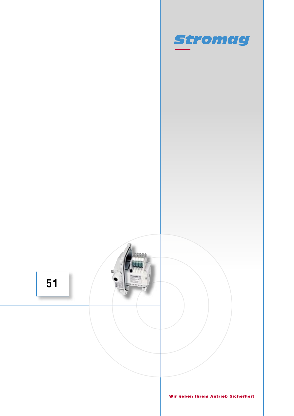
- Planetengetriebe: Kunststoff
- Präzise
- Sehr einfach einstellbar
- Gehäuse: Kunststoff oder Aluminumguss
- Planetary gears: plastics
- Precise
- Very simple adjustment
- Housing: Plastics or aluminium cast
Getriebe-Nocken-
Endschalter
Serie 51 / 51 DZ
Geared Cam
Limit switches
safety in motion
Page 2

Getriebe − Nocken − Endschalter Reihe 51 / 51 DZ
Geared Cam Limit Switches Series 51 / 51 DZ
Katalog − Nr. D 142
Alle Angaben über Getriebe − Nocken − Endschalter der Reihe
51 und Getriebe − Nocken − Endschalter mit Differenzzahn −
Getriebe der Reihe 51 DZ in Druckschriften älteren Datums
sind mit dem Erscheinen dieser Druckschrift nur noch bedingt
gültig.
Maß − und Konstruktionsänderungen behalten wir uns vor.
Stromag − Produkte entsprechen dem Qualitätsstandard
nach EN ISO 9001.
Inhalt Kapitel
Standardschalter 1
Allgemeines 1.1
Aufbau des Getriebe − Nocken − Endschalters 1.2
Aufbau Differenzzahn − Getriebe Reihe 51 DZ 1.3
Schaltpunkteinstellung 1.4
Blockverstellung 1.5
Typenschlüssel 1.6
Bestellbeispiel 1.6.1
Getriebedaten 1.7
Kontakte / Kontakttabelle 1.8
Nockenscheiben 1.9
Antrieb 1.10
Elastischer Antriebsflansch F bzw. F+M 1.11
Gehäuseausführungen 1.12
Schalter im Aluminium − Gehäuse 1.13
Kunststoff − Modul − Gehäuse Bauform B14 1.14
Kunststoff − Modul − Gehäuse Bauform B3 1.15
Modul − Gehäuse Bauform B5 1.16
Modul − Gehäuse Bauform B5 Zollern − Winde" 1.17
Catalogue No. D 142
This catalogue for geared cam limit switches series 51 and
geared cam limit switches with differential tooth gear series
51 DZ cancels and replaces all former editions.
We reserve the right to modify the dimensions and construc−
tions.
Stromag products comply with the Quality Standard to
EN ISO 9001.
Content Chapter
Standard switch 1
General 1.1
Construction of the geared cam limit switch 1.2
Construction of the differential tooth gear series 51 DZ 1.3
Switchpoint adjustment 1.4
Block Adjustment 1.5
Key to types 1.6
Ordering example 1.6.1
Gear data 1.7
Contacts / Contact table 1.8
Cam discs 1.9
Drive 1.10
Flexible driving flange F or F+M 1.11
Housing variants 1.12
Switches in aluminium housing 1.13
Plastic module housing / Construction B14 1.14
Plastic module housing / Construction B3 1.15
Module housing / Construction B5 1.16
Module housing / Construction B5 Zollern winch" 1.17
Sonderausführungen 2
Durchgeführte Antriebswelle 2.1
Potentiometerantrieb 2.2
Anzeigescheibe 2.3
Stillstandsheizung 2.4
Impulsgeber I 49 2.5
Motorische Blockverstellung 2.6
Ausführung für erhöhte Anforderungen
nach BGV C1 (VBG 70) (Bühnentechnik) 3
Allgemeines 3.1
Getriebedaten 3.2
Elektromagnet − Federdruck − Zahnkupplung EZX 0.1 3.3
Special executions 2
Inserted drive shaft 2.1
Potentiometer drive 2.2
Indicating plate 2.3
Anti − condensation heater 2.4
Pulse transmitter I 49 2.5
Motor − driven block adjustment 2.6
Variant for increased requirements according
to BGV C1 (VBG 70)1 (stage technology) 3
General 3.1
Gear data 3.2
Electromagnetic spring − applied toothed clutch EZX 0.1 3.3
Datum / Date 10.2008
1
Page 3

Getriebe − Nocken − Endschalter Reihe 51 / 51 DZ
Geared Cam Limit Switches Series 51 / 51 DZ
1 Standardschalter
1.1 Allgemeines
Getriebe − Nocken − Endschalter der Reihe 51 sind universell
einsetzbare, mechanische Schaltgeräte, mit denen eine Viel−
zahl von Umdrehungen einer Welle auf dem Drehwinkel der
eingebauten Nockenscheiben abgebildet wird. Von diesen
Nockenscheiben werden die mechanischen Schaltkontakte
betätigt.
Getriebe − Nocken − Endschalter werden überall dort einge−
setzt, wo Winkel oder Strecken nicht direkt durch Schaltge−
räte begrenzt werden können, sondern diese Begrenzung nur
indirekt über die Messungen des Drehwinkels einer Welle
möglich ist. Das klassische Beispiel für eine solche Anwen−
dung ist die Begrenzung des Hakenweges eines Kranhub−
werkes.
Besonders dort, wo im Zusammenhang mit einer möglichen
Personengefährdung zwangstrennende Schaltkontakte
nach EN 60947 T5 − 1, IEC 947 − 5 − 1 vorgeschrieben sind,
gibt es keine wirtschaftliche Alternative zu Getriebe − Nok−
ken − Endschaltern.
Abnahmen bzw. Zulassungen
Abnahmen bzw. Zulassungen für Standardausführungen:
Germanischer Lloyd Nr. 11300 − 98 HH (ohne DZ)
CSA Nr. 201 644 (ohne Zusatzanbauten)
1 Standard switches
1.1 General
51 series geared cam limit switches are universal mechanical
switching devices that have been designed for use in con−
junction with cam discs based on a specific angle of rotation
for indication of a large number of shaft revolutions. These
cam discs serve to operate mechanical contacts.
Geared cam limit switches are used wherever angles or rou−
tes cannot be directly limited by closing devices but only indi−
rectly via measurements of the angle of rotation.
A classic example of such an application is limitation of the
hook travel of crane hoisting gear.
Especially where there is a danger to persons and the use
of positive opening switching contacts is required accor−
ding to EN 60947, part 5 − 1, IEC 947 − 5 − 1, the use of ge−
ared cam limit switches is the most efficient alternative.
Survey and approval
Survey and approval for standard executions:
Germanischer Lloyd No. 11300 − 98 HH (without DZ)
CSA No. 201 644 (without supplementary fittings)
Die besonderen Vorteile der Getriebe − Nocken − End−
schalter der Reihe 51 sind:
S Patentierte Planeten − Getriebe
Formschlüssiges, reibungsarm laufendes Planetenge−
triebe mit selbsthemmender, selbstarretierender Schnek−
kenverstellung der Nockenscheiben.
S Im Gehäuse feststehende Nockenverstellung
Die Verstellschnecken der Nockenscheiben sind so an−
geordnet, daß sie aus der gleichen Richtung zu erreichen
sind, wie die Anschlüsse der Kontakte. Damit ist optimale
Erreichbarkeit auch unter beengten Einbauverhältnissen
gewährleistet. Die Verstellung ist auch während des Be−
triebes möglich. Die Einfachheit und Genauigkeit der Nok−
kenverstellung ist unübertroffen.
S Modularer Aufbau
Durch konsequente Verwendung von gleichen Teilen so−
wohl im Getriebe als auch beim Gehäuse wird eine wirt−
schaftliche und flexible Herstellung und Montage garan−
tiert.
S Patentierte Blockverstellung
Das Verstellen aller Schaltkontakte gemeinsam ist durch
eine einzige Verstellschnecke (schwarz) möglich, ohne
daß die Schaltpunkte der einzelnen Schaltkontakte zuein−
ander verändert werden.
The particular advantages of 51 series geared cam limit
switches are as follows:
S Patented planetary gearing
Low friction planetary gearing with irreversible, self −
locking worm adjustment of the cam discs.
S Fixed cam adjustment in housing
The adjusting worms of the cam discs are arranged so
that they can be accessed from the same direction as the
contact connections for optimal accessibility in confined
conditions. Adjustment is possible during operation. The
simplicity and accuracy of the cam adjustment is unex −
celled.
S Modular design
The consistent use of the same components for the gea−
ring and housing guarantees economical and flexible ma−
nufacture and assembly.
S Patented block adjustment
The adjustment of all switching contacts jointly is made
possible by a single adjusting worm (black) without the
switching points of the individual switching contacts being
altered with respect to each other.
S Große Nockenscheiben − Durchmesser
Das bedeutet eine gute Einstellbarkeit und eine hohe
Schaltpunktwiederholgenauigkeit.
Datum / Date 10.2008
S Large cam disc diameter
This means good adjustability and high switching point
repeat accuracy.
2
Page 4

Getriebe − Nocken − Endschalter Reihe 51 / 51 DZ
Geared Cam Limit Switches Series 51 / 51 DZ
1.2 Aufbau des Getriebe − Endschalters
Der Getriebe − Endschalter 51 besteht aus einem Getriebe −
und Schalterteil, die in einem Gehäuse untergebracht sind.
Das Drehmoment wird formschlüssig von der durchgehenden
Antriebswelle auf die Nockenscheiben übertragen. Die Getrie−
beteile sind aus hochwertigem Kunststoff gefertigt und laufen
wartungsfrei.
Getriebe − Endschalter der Reihe 51 werden standardmäßig in
der Schutzart IP00/IP20 als Einbauschalter geliefert. Gegen
Mehrpreis kann der Schalter in einem Aluminium − Gehäuse
der Schutzart IP65 oder in einem GF − verstärkten Polycarbo−
nat Gehäuse in der Schutzart IP66 geliefert werden.
Die Gebrauchslage ist beliebig.
Die Dauer − Betriebstemperatur beträgt − 40_C bis +80_C.
Die Schaltkontakte können mit Schraub − oder Flachsteck−
anschluß 6,3 mm ausgeführt sein.
1.3 Aufbau des Differenzzahn − Getriebes
Getriebeaufbau
Das Differenzzahn − Getriebe der Reihe 51 basiert auf der nor−
malen Planetenstufe der Reihe 51, bei der die Nockenschei−
ben zur Betätigung der Schaltkontakte auf die Planetenträger
aufgesteckt sind.
Die Nockenscheibe des Differenzzahn − Getriebes hat dazu
im Unterschied eine eigene Innenverzahnung mit gleichem
Teilkreisdurchmesser wie das Hohlrad. Allerdings ist die Zäh−
nezahl der Nockenscheibe um 3 Zähne größer. Die Planeten−
räder greifen gleichzeitig in beide Verzahnungen ein.
Dadurch verdreht sich bei jedem Umlauf der Planetenräder
die Nockenscheibe um den Unterschied der Zähnezahlen
von Hohlrad und Nockenscheibe.
Das ergibt eine Untersetzung pro Getriebestufe von
69,98.
Der Vorteil dieser Getriebeausführungen ist, daß die Abmes−
sungen der Differenzzahn − Getriebe gleich sind mit den Ab−
messungen der bisherigen Planetenstufen. Sie passen aus
diesem Grund in die gleichen Gehäusegrößen. Auch die
Kombination mit den Voruntersetzungen und mit normalen
Planetenstufen sind dadurch gewährleistet. Die unterschiedli−
chen Schaltstufen sind sogar gemischt verwendbar, so daß
zwei nebeneinander liegende Nockenscheiben eine um den
Faktor 16 unterschiedliche nutzbare Umdrehung haben kön−
nen. Bei Parallelschaltung der nebeneinander liegenden
Schaltkontakte würde der Stromkreis erst unterbrochen, wenn
beide Kontakte geschaltet sind. Die Schaltgenauigkeit wird
damit um den Faktor 16 verbessert, bei sehr geringem Mehr−
aufwand.
Die technischen Daten der Getriebe entnehmen Sie bitte der
Tabelle 2. Die kleinste mögliche Getriebe − Untersetzung ist
69,98. Bei Getriebeuntersetzungen kleiner als diese Unterset−
zung sind die normalen Planeten − Getriebe der Reihe 51 zu
verwenden, s. Tabelle 1.
Die Abmessungen der Getriebegröße 1 der DZ − Getriebe ent−
sprechen der Getriebegröße 1 der Planeten − Getriebe. Damit
gelten alle Maßzeichnungen dieses Kataloges für beide Aus−
führungen.
1.2 Construction of the geared limit switch
The geared limit switch 51 consists of a gearbox and switch
combination which are located within a housing. The torque
is positively transferred from the input shaft to the cam discs.
The gearbox components are made of high − quality synthetic
material and are maintenance − free.
The standard geared limit switches of series 51 are supplied
as skeleton switches with protection IP00/IP20. Limit switches
in an aluminium housing of protection IP65 or GF − reinforced
polycarbonate of protection IP66 can be supplied at extra
price.
Mounting as required.
The continuous service temperature is − 40_C to +80_C. The
switching contacts can optionally be executed with screw ter−
minal connection or flat plug connection 6.3 mm.
1.3 Construction of the differential tooth gear
Gear construction
The differential tooth gear of series 51 is based on the normal
planetary step of series 51, whereas the cam discs for actua−
tion of the switching contacts are fitted to the planetary carrier.
Difference: the cam disc of the differential tooth gear is provi−
ded with an own internal toothing having the same pitch circle
diameter as the internal geared wheel. However, the cam disc
has 3 teeth more. The planetary wheels catch simultaneously
into both toothings.
With every rotation of the planetary wheels the cam disc
turnes by the difference of the gear number of the geared
wheel and the cam disc.
Hence it follows a gear reduction of 69.98 per gear step.
This gear execution offers the advantage that the dimensions
of the differential tooth gear are identical with the dimensions
of the former planetary steps. Therefore they suit into the
same housing sizes. The possibility of combination with pre −
reductions and with normal planetary steps as well is assured.
It is even possible to mix the different switching steps so that
two adjacent cam discs may have a useful travel differing by
factor 16. With parallel operation of the adjacent switching
contacts the current circuit would only be interrupted when
both contacts are actuated. Thereby the switching accuracy
is improved by factor 16, whereas the additional expenditure
is very low.
The technical data of the gear are stated in table 2. The smal−
lest possible gear reduction is 69.98. For smaller gear reduc−
tions use the normal planetary gears of series 51, see table
1.
The dimensions of gear size 1 of the differential tooth gear
correspond to gear size 1 of the planetary gear. So all dimen−
sional drawings of this catalogue apply to both executions.
Datum / Date 10.2008
3
Page 5
Getriebe − Nocken − Endschalter Reihe 51 / 51 DZ
Geared Cam Limit Switches Series 51 / 51 DZ
Die Antriebswelle kann wie bei den normalen Planetenstufen
nach hinten verlängert werden, so daß hinter dem Getriebe−
schalter Inkrementalgeber, Impulsgeber oder Multiturn − Ab−
solutwertgeber angebaut werden können, s. Seiten 20 und
23.
Beschränkungen
Nicht mehr möglich bei dieser Getriebe − Ausführung ist die
konkurrenzlos einfache Blockverstellung der normalen Reihe
51. Kunden die diese Eigenschaft benötigen, verwenden wei−
terhin die normale Reihe 51. Außerdem ist bei dieser Ausfüh−
rung der Einbau einer Potikupplung nicht mehr möglich. Sol−
len Potentiometer oder Singleturn − Absolutwertgeber
angebaut werden, sind weiterhin die normalen Schaltstufen
der Reihe 51 zu verwenden.
Vorteile der DZ − Getriebe
Bei gleicher Getriebe − Untersetzung reduziert sich die
Baulänge der Getriebeschalter um ca. 19 mm.
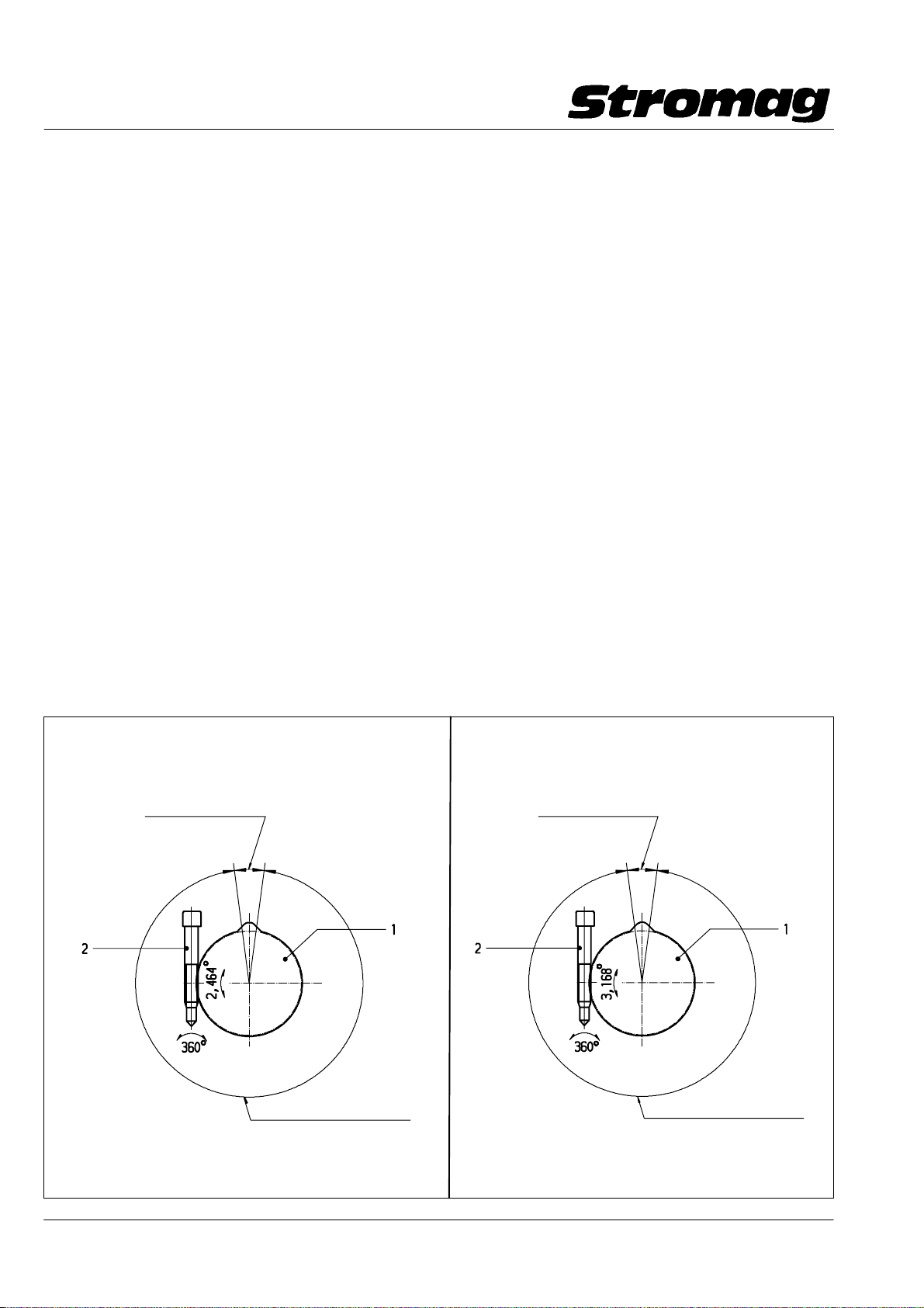
1.4 Schaltpunkteinstellung
Die Schaltpunkteinstellung jedes einzelnen Kontaktes erfolgt
durch einen selbsthemmenden Schneckenantrieb (2) stufen−
los auf die Nockenscheibe (1). Der Schaltpunktabstand kann
innerhalb des nutzbaren Umdrehungsbereiches stufenlos ein−
gestellt werden. Eine Umdrehung an der Verstellschnecke
entspricht einer Drehung der Nockenscheibe von 2,464_
(Reihe 51) und 3,168° (Reihe 51 DZ). Die Verstellung kann in
beiden Drehrichtungen erfolgen.
Die Schaltpunkte können unabhängig voneinander eingestellt
werden. Ein Feststellen irgendwelcher Teile ist nach der Ein −
stellung nicht erforderlich.
As for the normal planetary steps, the input shaft can be ex−
tended to the rear side so that incremental encoders, pulse
generators or multiturn absolute value encoders can be
mounted behind the gear switch, see pages 20 and 23
Restrictions
The simple block adjustment (which is without any competi−
tion) of the normal series 51, however, cannot be used for this
gear execution. Customers requiring this characteristic still
use the normal series 51. It is not possible, too, to mount a
potentiometer coupling. If intended to fit potentiometers or
singleturn absolute value encoders, the normal switching
steps of series 51 have still to be used.
Advantages of the differential tooth gears
With the same gear reduction, the assembly length of the
geared switch reduces by approx. 19 mm.
1.4 Switching point adjustment
The switching point adjustment of each contact is infinitely
made on the cam disc (1) by means of a self − locking worm
gear (2). The switching point distance is infinitely adjustable
within the range of usable revolutions. One revolution of the
controllable worm corresponds to a revolution of 2.464_ (Se−
ries 51) and 3.168° (Series 51 DZ) of the cam disc. The ad−
justment can be made in both directions.
The switching points are independently adjustable. Locking
of any parts after adjustment is not necessary.
DD − _140182
Reihe / Series 51
Wirksamer Nockenwinkel
Effective cam angle
Nutzbarer Winkel der Nockenscheibe
Useful angle of the cam disc
Reihe / Series 51 DZ
Wirksamer Nockenwinkel
Effective cam angle
Nutzbarer Winkel der Nockenscheibe
Useful angle of the cam disc
DD1 − 40702V
Datum / Date 10.2008
4
Page 6
Getriebe − Nocken − Endschalter Reihe 51 / 51 DZ
Geared Cam Limit Switches Series 51 / 51 DZ
1.5 Blockverstellung
Durch die Bauweise des Getriebes mit Planetenstufen ergibt
sich ab der nutzbaren Umdrehung 17,5 (Getriebe − Größe 2)
die Möglichkeit einer Blockverstellung. Diese ist standardmä−
ßig eingebaut.
Dabei ist die letzte Getriebestufe ebenfalls mit einer Verstell−
schnecke, in schwarzer Farbe, ausgerüstet.
Die Blockverstellung ermöglicht, zusätzlich zur Einzeleinstel−
lung, eine gemeinsame Verstellung aller Nockenscheiben.
Die Schaltposition der Einzelkontakte zueinander bleiben da−
bei unverändert.
Achtung!
Um bei der Reihe 51 DZ gleiche System−
maße beizubehalten, ist auch die Blockverstellungsstufe
eingebaut.
Die eingebaute Verstellschnecke wirkt aber nicht als
Blockverstellung.
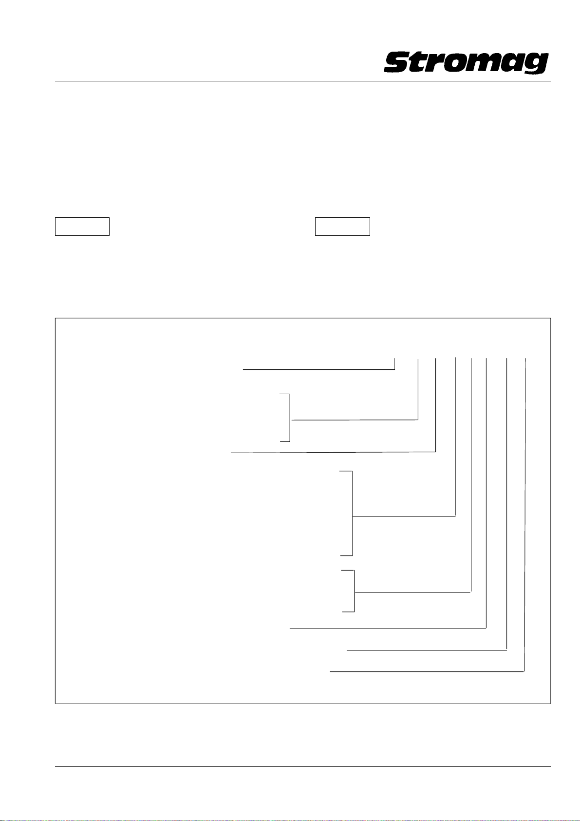
1.6 Typenschlüssel / Key to types
Nutzbare Umdrehung / Usable revolutions
(Getriebedaten s. / Gear data see Tab. 1 + 2)
1.5 Block adjustment
As a standard the planetary gear construction allows a block
adjustment in addition to the individual contact adjustment
from the usable revolution 17.5 (gear size 2).
The final gear stage is also provided with an adjusting worm,
coloured black.
All cam discs can be commonly adjusted by means of this
adjusting worm.
The relative adjustments of the individual contacts to each
other are not modified.
Caution!
To maintain identical system dimensions
with series 51 DZ, the block adjustment step is mounted.
The built − in adjusting worm, however, does not act as
block adjustment.
DZ
NHC
75 B M N K 4 99 A
DZ Differenzzahn − Getriebe / Differential tooth gear
N nur bei Getriebe Gr. 1 (ohne Blockverstellung)
for gearbox size 1 only (without block adjustment)
B Blockverstellung / Block adjustment
M Modul − Gehäuse / Modular housing
H Schalter eingebaut im Aluminium − Gehäuse mit hohem Deckel
(Beschreibung s. Kap. 1.12.2; Maßbild s. Kap. 1.13)
Switch mounted into aluminium housing with high cover
(Description see chap. 1.12.2; Dimensional fig. see chap. 1.13)
N Schalter eingebaut im Aluminium − Gehäuse mit niedrigem Deckel
(Beschreibung s. Kap. 1.12.2; Maßbild s. Kap. 1.13)
Switch mounted into aluminium housing with low cover
(Description see chap. 1.12.2; Dimensional fig. see chap. 1.13)
C Schalter eingebaut im Kunststoff − Gehäuse mit kurzer Haube
Switch mounted into synthetic housing with short cap
K Schalter eingebaut im Kunststoff − Gehäuse mit langer Haube
Switch mounted into synthetic housing with long cap
Anzahl der eingebauten Kontakte / No. of contacts fitted
Kontaktbezeichnung (s. Tabelle 3) / Type of contacts fitted (see table 3)
Anzeige Blockverstellung / Indication "block adjustment" (Option)
Nur auf Anfrage
Only on request
Datum / Date 10.2008
5
Page 7
Getriebe − Nocken − Endschalter Reihe 51 / 51 DZ
Geared Cam Limit Switches Series 51 / 51 DZ
1.6.1 Bestellbeispiel
Notwendige Bestellangaben für Standard − Getriebeschalter:
Reihe / Series
51
1.6.1 Ordering example
Ordering data required for standard geared switches:
Typ / Type 75 BMH − 499 A s. Kapitel / see Chapter 1.6
Bauform / Construction B3 s. Kapitel / see Chapter 1.12 − 1.17
Schutzart / Protection IP65 s. Kapitel / see Chapter 1.12 − 1.17
Ergänzende Angaben bei Sonderausführungen bzw. bei Op−
Additional data for special types and options:
tionen:
S Nockenscheiben:
Angabe des wirksamen Nockenwinkels falls abweichend
von der 15_ Standardnockenscheibe, s. auch Kap. 1.9.
S PTC − Heizung:
Angabe der Anschlußspannung, s. auch Kap. 2.4.
S Geberanbau:
Bei einer Anfrage bzw. Bestellung sind unbedingt verbind−
liche Maß − bzw. Datenblätter des einzubauenden Gebers
erforderlich, s. auch Kap. 2.1.
S Cam discs:
Data on effective cam angle if deviating from the 15_
standard cam disc, see also Chapter 1.9.
S PTC heater:
Data on supply voltage, see also Chapter 2.4.
S Sensor:
For enquiries or orders, binding dimension and data
sheets on the sensor to be fitted are required, see also
Chapter 2.1.
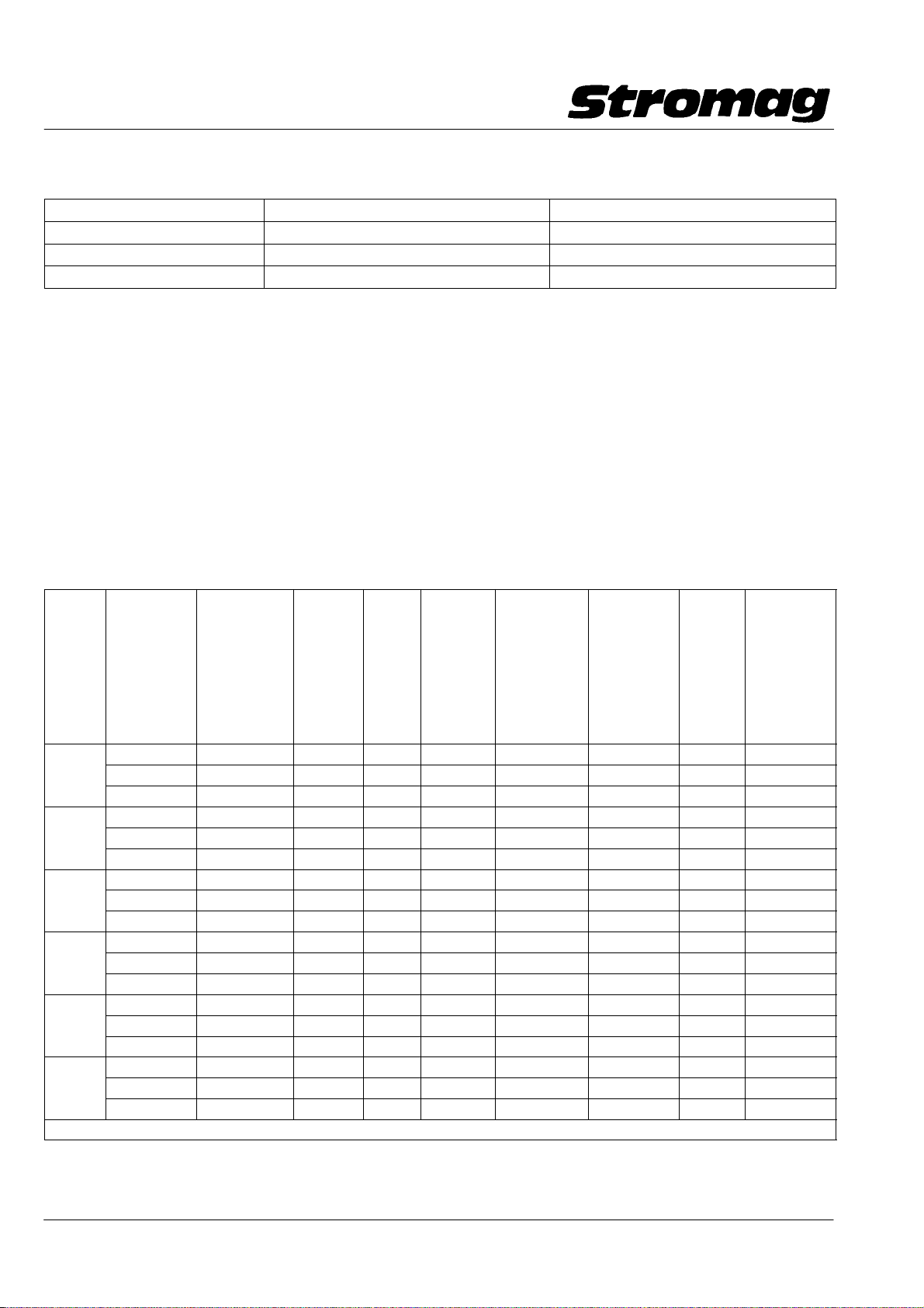
1.7 Tabelle / Table 1
Getriebedaten / Gear data Reihe 51
Getrie−
begröße
Gear
size
1)
Nur als Öffner − Kontakt zu verwenden / Only use as normaly closed contact
Nenn − Um−
drehungen
für Nocken−
scheibe 15_
Nominal
revolutions
for cam disc
15_
4,1 4,16 4,285 − 1x4,285 84 0,01 − 0,02 1000 0,67
1 6,5 6,88 7,083 1,653 1x4,285 50,8 0,01 − 0,02 1200 1,1
11 11,23 11,56 2,698 1x4,285 31,14 0,02 − 0,04 1500 1,8
17,5 17,84 18,361 − 2x4,285 19,6 0,03 − 0,06 1800 2,9
2 29,0 29,5 30,35 1,653 2x4,285 11,86 0,05 − 0,1 1800 4,7
48 48,13 49,538 2,698 2x4,285 7,27 0,08 − 0,16 1800 7,7
75 76,45 78,678 − 3x4,285 4,57 0,13 − 0,3 1800 12,2
3 125 126,39 130,054 1,653 3x4,285 2,77 0,21 − 0,42 1800 20,2
205 206,26 212,272 2,698 3x4,285 1,69 0,35 − 0,68 1800 33
323 327,6 337,135 − 4x4,285 1,06 0,6 − 1,17 1800 52
4 540 541,5 557,284 1,653 4x4,285 0,65 0,92 − 1,8 1800 87
880 883,8 909,59 2,698 4x4,285 0,4 1,5 − 2,9 1800 141
1384 1403,7 1444,62 − 5x4,285 0,25 2,4 − 4,7 1800 224
5 2288 2320,2 2387,96 1,653 5x4,285 0,15 3,9 − 7,7 1800 371
3735 3787,1 3897,58 2,698 5x4,285 0,09 6,5 − 12,7 1800 606
5900 6014,77 6190,204 − 6x4,285 0,06 10,3 − 20,1 1800
6 9800 9942,42 10232,407 1,653 6x4,285 0,04 17,0 − 33,3 1800
16000 16227,86 16701,17 2,698 6x4,285 0,02 27,8 − 54,2 1800
Nutzbare
Umdrehungen
theo. bei Nok−
kenscheiben
15_
Usable revs.
theor. at cam
discs 15_
Ge −
triebe i
Gear −
ratio i
Vorsatz−
stufe
Input/
output
stage
Anzahl
i
ges.
Planeten −
stufen
No. of
planetary
stages i
1 Umdr. der
Antriebswelle
= Grad an der
Nocken−
scheibe
1 rev. of the
drive shaft −
corresp. to an
ang. motion of
cam disc =_
Rückschalt −
Umdr. an der
Antriebswelle
für Schnapp−
schalter
Reset rev. at
driving shaft
for snap ac−
tion
max.
Antriebs−
drehzahl
max.
drive
speed
−1
min
min. Antriebs−
drehzahl (nur
bei Wechsler)
min. drive
shaft (only for
change − over
contact)
−1
min
1)
1)
1)
Datum / Date 10.2008
6
Page 8
Getriebe − Nocken − Endschalter Reihe 51 / 51 DZ
Geared Cam Limit Switches Series 51 / 51 DZ
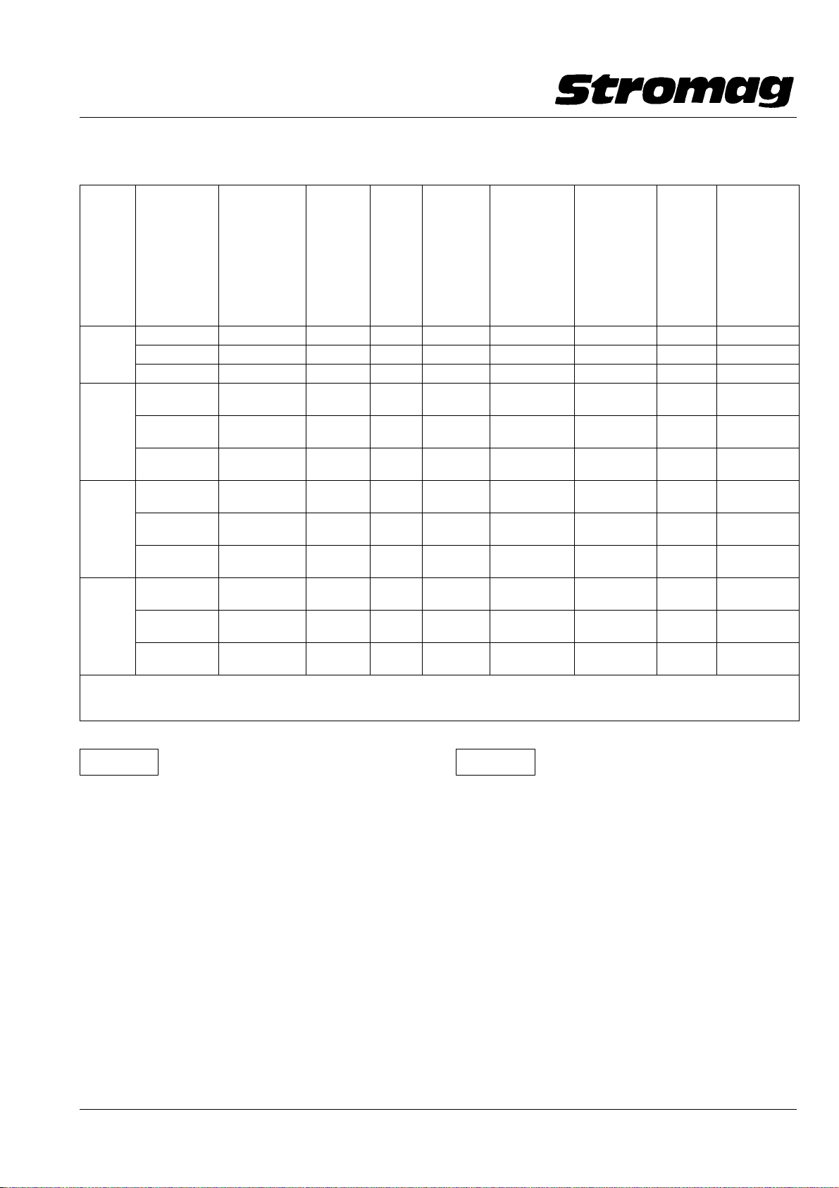
Tabelle / Table 2
Getriebedaten / Gear data 51 DZ
Getrie−
begröße
Gear
size
1 110 111,1 115,68 1,653 1x 69,98 3,11 0,19 − 0,4 1800 18,0
2
3
4
1 Umdrehung der Verstellschnecke entspricht 3,168° an der Nockenscheibe
1)
Nenn − Um−
drehungen
für Nocken−
scheibe 15_
Nominal
revolutions
for cam disc
15_
67 67,23 69,98 − 1x 69,98 5,14 0,11 − 0,22 1800 10,9
180 181,4 188,8 2,698 1x 69,98 1,90 0,31 − 0,6 1800 29,4
280 288,1 299,86 − 1x 4,285
470 476,25 495,67 1,653 1x 4,285
770 777,3 809,02 2,698 1x 4,285
1200 1234,5 1284,9 − 2x 4,285
2000 2040,7 2123,97 1,653 2x 4,285
3300 3330,9 3466,66 2,698 2x 4,285
5200 5290,2 5505,87 − 3x 4,285
8700 8744,7 9101,2 1,653 3x 4,285
14200 14272,9 14854,8 2,698 3x 4,285
Revolution of the adjusting worm corresponds to 3.168° at the cam disc
Nur als Öffner − Kontakt zu verwenden / Only use as normally closed contact
Nutzbare
Umdrehungen
theo. bei Nok−
kenscheiben
15_
Usable revs.
theor. at cam
discs 15_
Ge −
triebe i
Gear −
ratio i
Vorsatz−
stufe
Input/
output
stage
Anzahl
i
ges.
Planeten −
stufen
No. of
planetary
stages i
1x69,98
1x69,98
1x69,98
1x69,98
1x69,98
1x69,98
1x69,98
1x69,98
1x69,98
1 Umdr. der
Antriebswelle
= Grad an der
Nocken−
scheibe
1 rev. of the
drive shaft −
corresp. to an
ang. motion of
cam disc =_
1,20 0,5 − 1,0 1800 46,7
0,73 0,84 − 1,7 1800 77,1
0,44 1,35 − 2,6 1800 125,0
0,28 2,1 − 4,1 1800 199,0
0,17 3,5 − 10,3 1800 330,0
0,1 5,5 − 11,3 1800 539,0
0,06 9,1 − 17,8 1800 856,0
0,04 15,1 − 29,5 1800 1415,0
0,02 24,7 − 48,2 1800 1)
Rückschalt −
Umdr. an der
Antriebswelle
für Schnapp−
schalter
Reset rev. at
driving shaft
for snap ac−
tion
max.
Antriebs−
drehzahl
max.
drive
speed
−1
min
min. Antriebs−
drehzahl (nur
bei Wechsler)
min. drive
shaft (only for
change − over
contact)
min
−1
Achtung!
Bedingt durch die langsame Betätigungs−
geschwindigkeit der Schaltkontakte aufgrund der hohen
Getriebeuntersetzungen wird das Umschaltverhalten der
Kontakte negativ beeinflußt.
Bei Getriebegröße 6 sollten deshalb nur noch die Öffner−
kontakte der Schalter genutzt werden.
Vor Verwendung analoger Rückmeldesysteme (z.B. Poti)
ist Rücksprache mit den technischen Abteilungen nötig.
Caution!
Due to the slow actuation speed of the
switching contacts caused by the high gear reductions,
the change − over behaviour of the contacts is affected
negatively.
From gear size 6 it is therefore recommended to use only
the normally − closed contacts of the switches.
Before using analog feedback systems (e.g. potentiome−
ter) please consult our technical department.
Datum / Date 10.2008
7
Page 9
Getriebe − Nocken − Endschalter Reihe 51 / 51 DZ
yp
gp
IEC947−5−1
struktion
y
Normally
Silber/
schluß
Geared Cam Limit Switches Series 51 / 51 DZ
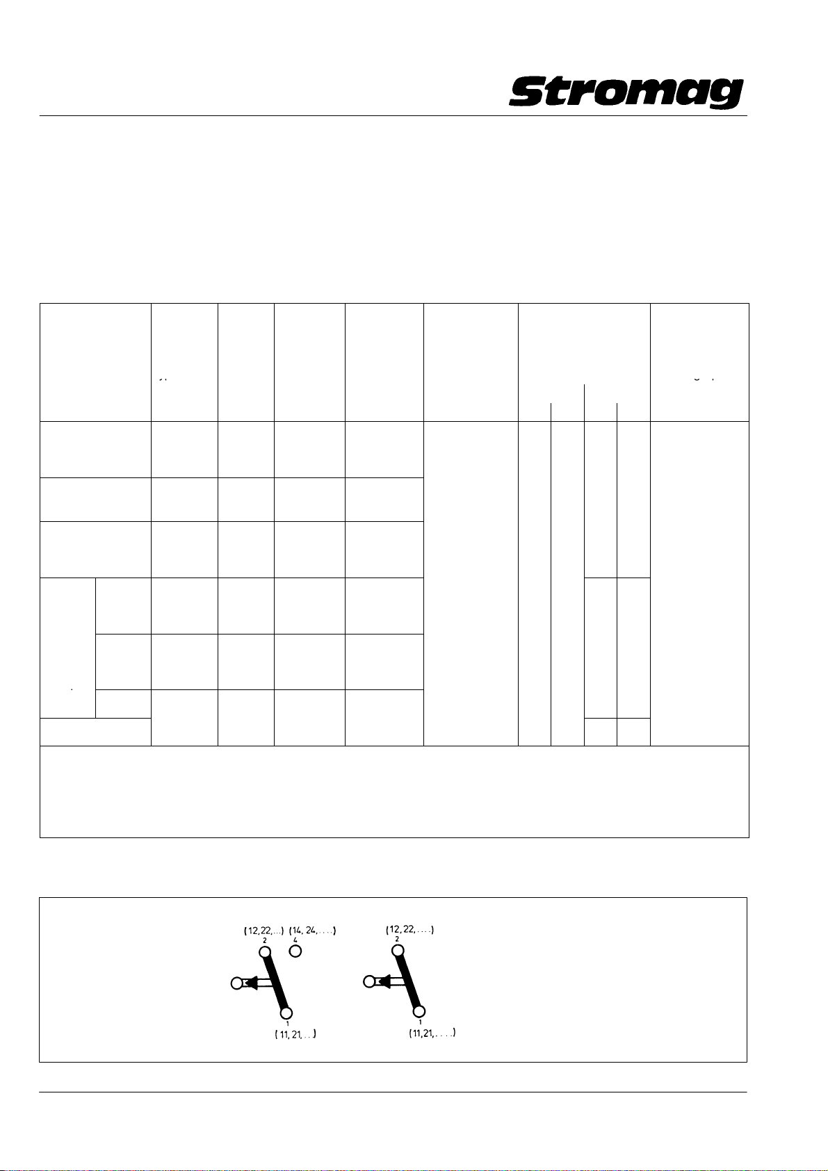
1.8 Kontakte
Die Kontakte können, je nach Art, über Schraubanschlüsse
für Leiterquerschnitte 2x0,75 mm
2
/AWG 18 bis 2x1,5 mm
/AWG 16 oder über Flachstecker 6,3x0,8 mm angeschlossen
werden.
Bei Kontakten mit Flachsteckanschluß sind bei Spannungen
> 25V AC bzw. 60V DC isolierte Flachsteckhülsen zu verwen−
1.8 Contacts
The contacts can either be connected through screw termi−
2
nals for a cable cross sections of 2x0.75 mm
2x1.5 mm
2
/AWG 16or through flat plugs 6.3x0.8 mm.
For contacts with flat − plug connection, insulated flat − plug
receptacles must be used at voltages above 25V AC and 60V
DC.
den.
Tabelle / Table 3
Kontaktbezeich −
nung
Contact designation
1)
99
1)
99P
1) 3)
99G
Nicht für
Neukon−
92
struktion
Not for
new
97
con−
struction
1)
Therm. Dauerstrom Ith = 10A; Bemessungsisolationsspannung U
Thermal permanent current Ith = 10A; Reference insulation voltage U
2)
Therm. Dauerstrom Ith = 6A; Bemessungsisolationsspannung U
Thermal permanent current Ith = 6A; Reference insulation voltage U
3)
Kontakte 99G und 97 für SPS − Anwendungen (Goldkontakte) / Contacts 99G and 97 for PLC applications (gold contacts)
4)
Bei Schraubenanschluss zulässiger Leiterquerschnitt: 0,5 − 1,5 mm2/For screw terminal admissible cable cross section AWG 22 − 16
99T
96
4)
2)
2)3)
2)
Kontaktart
Contact
type
Wechsler
Change −
over cont.
Wechsler
Change −
over cont.
Wechsler
Change −
over cont.
Wechsler
Change −
over cont.
Wechsler
Change −
over cont.
Öffner
Normall
closed
contact
Kontakt−
werkstoff
Contact
material
Silber
Silver
Silber/
Silver
Gold
Silber/
Silver
Gold
Silber/
Silver
Schalt −
system
Switch
actuation
Schnapp −
schaltung
Snap action
Schnapp −
schaltung
Snap action
Schnapp −
schaltung
Snap action
Schnapp −
schaltung
Snap action
Schnapp −
schaltung
Snap action
Tast −
schaltung
push action
Kontaktan−
schlußart
Type of
contact
Zwangstrennung
nach
Positive opening
to
connection EN60947T5 − 1
−
−
Schrauban −
schluß
Screw termi−
nal
Flachstecker
6,3
Flat plug 6,3
Schrauban −
schluß
Screw termi−
nal
Schrauban −
ja/yes 1.5 230 10
schluß
Screw termi−
nal
Schrauban −
schluß
Screw termi−
nal
Schrauban −
schluß
Screw termi−
nal
= 250V bei Verschmutzungsgrad 3
i
= 250V at pollution degree 3
i
= 250V bei Verschmutzungsgrad 3
i
= 250V at pollution degree 3
i
Elektrische Daten
Electrical data
nach/to EN 60947 − 5 − 1
AC − 15 DC − 13
I[A] U[V] I[A] U[V]
0,5 60
− −
0,5 60
2
/AWG 18to
mechanische
Lebensdauer
in Mio
Schaltungen
Mech. life in mio.
switching opera −
tions
Datum / Date 10.2008
Wechsler
Change over contact
99
99P
99G
Öffner
Normally closed contact
96
99T
8
Page 10

Getriebe − Nocken − Endschalter Reihe 51 / 51 DZ
Geared Cam Limit Switches Series 51 / 51 DZ
Typentabelle / Table of types
nutzbarer Umdrehungsbereich
Usable revolution
Reihe / Series
51 + 51 DZ
4,1
6,5
11,0
17,5
29,0
48,0
75,0
125,0
205,0
323,0
540,0
880,0
1384,0
2288,0
3735,0
5900,0
9800,0
16000,0
*
67
110
180
280
470
770
1200
2000
3300
5200
8700
14200
mit Wechsler − Kontakt
with change − over contact
99
Reihe/Series 51
1)
...NM/DZM 299
...NM/DZM 499
...NM/DZM 699
...NM/DZM 899
...BM/DZM 299
...BM/DZM 499
...BM/DZM 699
...BM/DZM 899
...BM/DZM 299
...BM/DZM 499
...BM/DZM 699
...BM/DZM 899
...BM/DZM 299
...BM/DZM 499
...BM/DZM 699
...BM/DZM 899
...BM 299
...BM 499
...BM 699
...BM 899
...BM 299
...BM 499
...BM 699
...BM 899
mit Öffner − Kontakt
with normally closed contact
96
Reihe/Series 51 + 51 DZ
1)
...NM/DZM 296
...NM/DZM 496
...NM/DZM 696
...NM/DZM 896
...BM/DZM 296
...BM/DZM 496
...BM/DZM 696
...BM/DZM 896
...BM/DZM 296
...BM/DZM 496
...BM/DZM 696
...BM/DZM 896
...BM/DZM 296
...BM/DZM 496
...BM/DZM 696
...BM/DZM 896
...BM 296
...BM 496
...BM 696
...BM 896
...BM 296
...BM 496
...BM 696
...BM 896
Größe
Size
1 A
1 B
1 C
1 D **
2 A
2 B
2 C
2 D **
3 A
3 B
3 C
3 D **
4 A
4 B
4 C
4 D **
5 A
5 B
5 C
5 D **
6 A
6 B
6 C
6 D **
1) Den gewünschten nutzbaren Umdrehungsbereich einsetzen / Insert the required usable revolution range
* Größere nutzbare Umdrehungen auf Anfrage / Higher usable revolutions on request
** Mehr als 8 Kontakte auf Anfrage möglich / More than 8 contacts on request
Im Aluminium − Gehäuse ist die Kontaktanzahl durch die Kombination von Getriebegröße und Schaltkontaktanzahl begrenzt
In an aluminium housing, the number of contacts is limited by the combination of gear size and number of switching contacts
Datum / Date 10.2008
9
Page 11
Getriebe − Nocken − Endschalter Reihe 51 / 51 DZ
Geared Cam Limit Switches Series 51 / 51 DZ
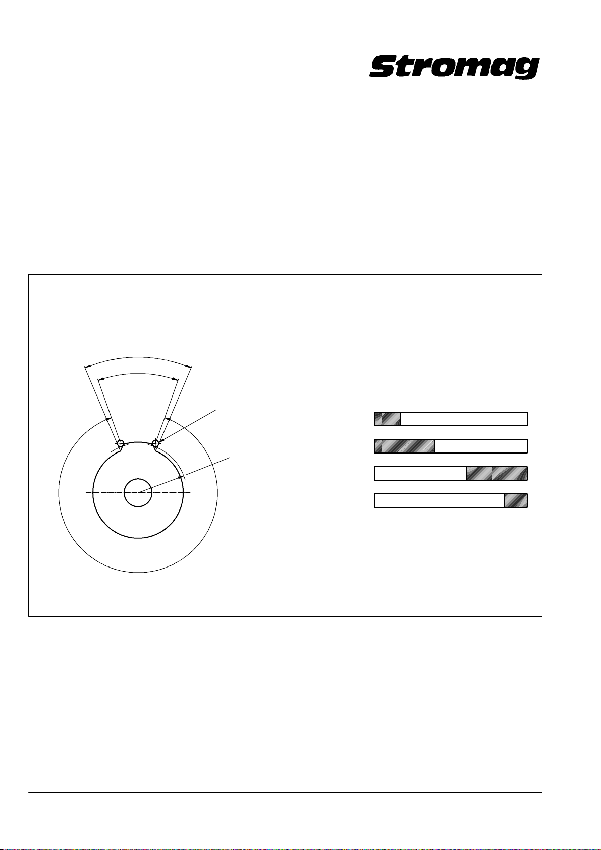
1.9 Nockenscheiben
Serienmäßig sind die Nockenscheiben mit 15_ − Auflauf−
nocken ausgerüstet. Auf Wunsch können ohne Mehrpreis
auch Nockenscheiben mit 40_ eingebaut werden.
Gegen Mehrpreis können beliebige Sondernockenwinkel her−
gestellt werden.
Werden bei Bestellung keine Nockenwinkel angegeben,
werden Nockenscheiben mit 15_ Nockenwinkel einge−
baut.
Für Sondernockenscheiben mit einem festen Programm bitte
ein Diagramm ähnlich der unten stehenden Beispielzeich−
nung angeben.
Die Nockenscheiben werden nach dem wirksamen Nockenwinkel benannt.
Bei Nockenscheiben der Reihe 51 entspricht dieser dem
Schaltpunktwinkel auf dem Schaltpunktradius der Nockenscheibe.
Der Fertigungswinkel ergibt sich aus der Konstruktion der Nockenscheibe.
Fertigungswinkel/Production angle
Wirksamer − Nockenwinkel
Effective cam angle
(Schaltpunktwinkel)
(Switching point angle)
Rollenhebel des Schaltkontaktes
Roller lever of switching contact
1.9 Cam discs
The cam discs are provided with 15_ contact cams as stan−
dard. Cam discs with 40_ can be provided at no extra charge
on request.
At extra charge various special cam angles can be made.
When not stating the cam angle on order placement, cam
discs with a cam angle of 15_ will be fitted.
For special cam discs with a firm program please provide a
diagram similar to the below shown example drawing.
The cam discs are designated according to their effective cam angle.
With 51 series cam discs, this corresponds to the switching point
angle on the switching point radius of the cam disc.
The production angle results from the design of the cam disc.
Beispielzeichnung
Example drawing
Kontakt / Contact Nockenwinkel / Cam angle _
0 15 60 270 315 360
1
Schaltpunkt − Radius
Switching point radius
Nutzbarer Winkel
der Nockenscheibe
Usable angle of cam disc
(360_ − α (wirksamer Nockenwinkel/effective cam angle) x i (Getriebeuntersetzung des Schalters/gear reduction of switch)
1.10 Antrieb
Der Antrieb kann radial, z.B. über einen Kettentrieb, oder
axial, z.B. über eine elastische Kupplung, erfolgen. Bei Ket−
ten − , Zahnrad − oder Zahnriementrieb ist die maximal zuläs−
sige radiale Belastung der Antriebswelle zu beachten (s. Dia−
gramm). Bei einigen Schutzartgehäusen ist zusätzlich zum
Gleitlager ein Rillenkugellager eingebaut. Bei Verwendung
dieser Gehäuse kann der zulässige Kurvenwert verdoppelt
Die nutzbaren Umdrehungen, die eine Nockenscheibe
an der Antriebswelle eines Getriebeschalters ermöglicht, ergibt sich folgendermaßen:
The usable number of revolutions of the drive shaft
of a geared switch enabled by a cam disc can be calculated as follows:
360°
1.10 Drive
The drive can be transmitted radially, e.g. by a chain, or axial−
ly, e.g. by a flexible coupling. With chain, toothed wheel or
synchronous belt drive, pay attention to the max. admissible
radial load (f max) of the input shaft (see diagram).
To some housings a grooved ball bearing is fitted in addition
to the plain bearing. When using these housings, the admis −
sible graphical values can be doubled.
2
3
4
werden.
Der ideale Antrieb erfolgt über eine drehsteife elastische
Kupplung mit geringen axialen und radialen Rückstellkräften.
Hierbei werden Fluchtfehler und Achsversatz ausgeglichen.
The ideal drive is transmitted by a torsionally stiff, flexible
coupling with low axial and radial restoring forces. Thereby
misalignment and axial displacement are balanced.
DD1_40294V
DD − _140184
Datum / Date 10.2008
10
Page 12
Getriebe − Nocken − Endschalter Reihe 51 / 51 DZ
Geared Cam Limit Switches Series 51 / 51 DZ
Achtung!
Bei Montage von Antriebselementen wie
z.B. Kettenräder keine unzulässigen axialen Kräfte aus−
üben. Axiale oder radiale Schläge auf die Welle vermei−
den.
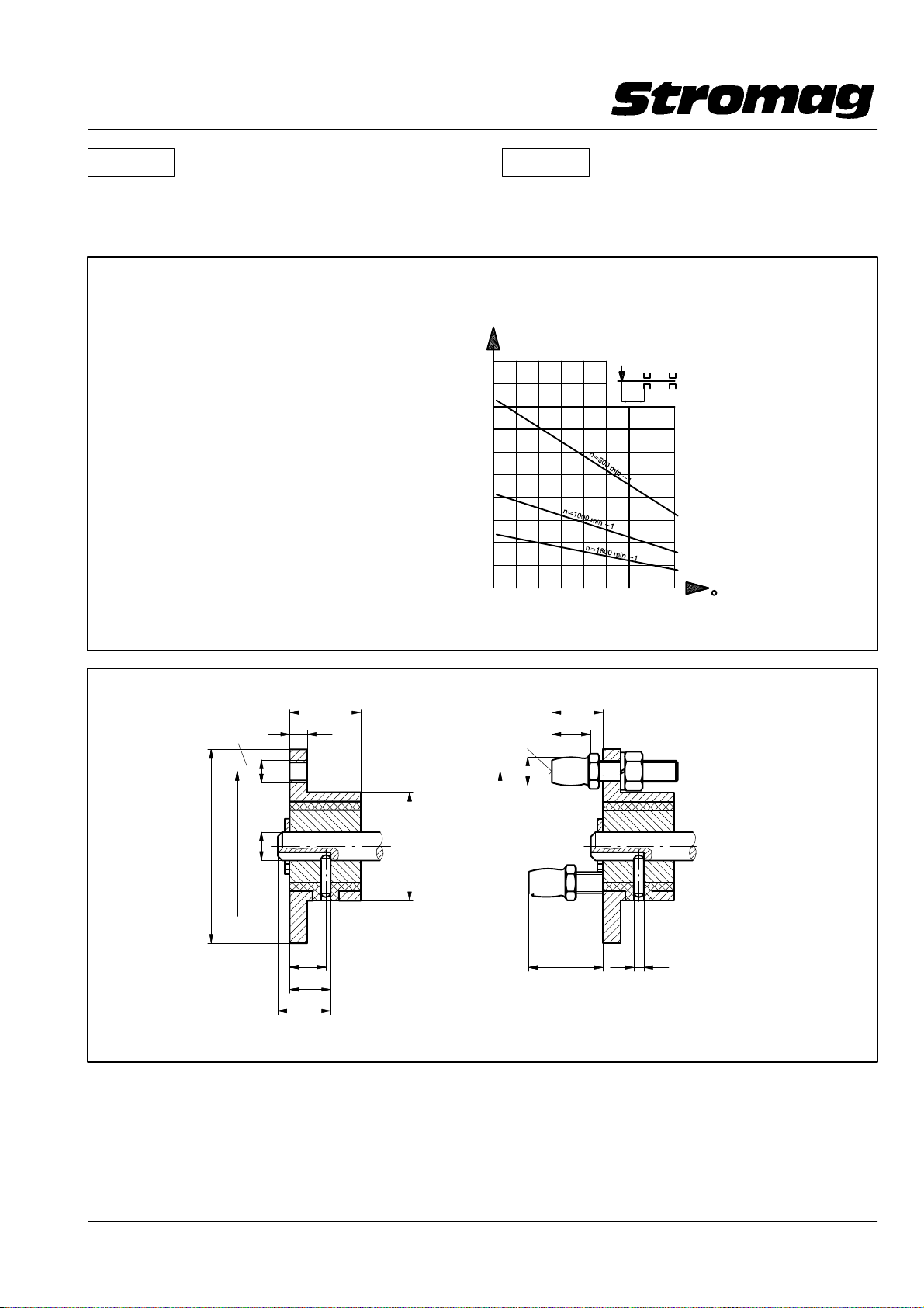
Beispiel / Example:
Bei / with n1 = 1800 min−1 / rpm
und / and
40_C Umgebungstemperatur
ambient temperature F
und / and
80_C Umgebungstemperatur
ambient temperature F
max
max
= 16 N
= 9 N
Caution!
When mounting driving elements, such as
chain wheels, do not exercise inadmissible axial forces.
Avoid axial or radial shocks onto the shaft.
F max.
N
100
90
80
13.5
70
60
50
Radialkraft / Radial Force
40
30
20
10
100 20304050607080 C
Umgebungstemperatur / Ambient Temperature
LAGER A − SEITE
LAGER B − SEITE
DD − _140161
Elast. Antriebsflansch F
Flexible drive flange F
3x120°
20
5
M6
ø54
±0.2
ø42
H7
h9
ø8
− 0.1
ø30
10
11.5
15
max. zulässige Betriebsdrehzahl:
max. adm. service speed: n = 1000 min
Verdrehwinkel bei/twisting angle at 5Nm: 5 ± 0,5_
1.11 Elastischer Antriebsflansch F bzw. F+M
Alle Ausführungen der Getriebe − Endschalter Reihe 51 kön−
nen zusätzlich mit elastischen Antriebsflansch F bzw. F+M
geliefert werden.
Bei Gehäuseform C/K ist die Verwendung von F+M − Flansch
nur auf Anfrage möglich.
14
Elast. Antriebsflansch F+M
Flexible drive flange F+M
3x120°
− 0.05
10
ø8
±0.2
ø42
22
ø3
−1
DD1_40170V
1.11 Flexible driving flange F or F+M
All executions of the geared limit switch series 51 can also be
supplied with flexible driving flange F or F+M.
With housing form C/K, the utilisation of a flange F+M is pos−
sible only on request.
11
Datum / Date 10.2008
Page 13

Getriebe − Nocken − Endschalter Reihe 51 / 51 DZ
Geared Cam Limit Switches Series 51 / 51 DZ
1.12 Gehäuseausführungen
1.12.1 Einbaugehäuse Schutzart: IP20/IP00
Diese Gehäuseausführung wird eingesetzt, wenn kundensei−
tig bereits ein Gehäuse zur Verfügung steht, in das der Getrie−
beschalter eingebaut werden kann. Er wird auch in den nach−
folgend beschriebenen Schutzgehäusen aus Aluminium
(Schutzart IP65) und Polycarbonat (Schutzart IP66) verwen−
det.
Der Schalter ist modulartig aufgebaut. Die Baulänge hängt ab
von der Getriebeuntersetzung und der Anzahl der eingebau−
ten Kontakte. Die Detailmaße entnehmen Sie bitte dem nach−
folgenden Maßbild.
Zur Befestigung stehen Füße und Gewindebohrungen an der
Stirnseite zur Verfügung.
Kontakte mit Schraubanschluß standardmäßig mit Berüh−
rungsschutz, Schutzart IP20.
Kontakte mit Flachsteckanschluß Schutzart IP00. Bei Span−
nungen > 25V AC oder 60V DC sind zum Erreichen einer
Handrückensicherheit isolierte Flachstecker zu verwenden.
Auch bei Öffnerfunktion muß der Schließeranschluß mit ei−
nem isolierten Stecker versehen sein.
1.12.2 Aluminium − Schutzgehäuse Schutzart IP65
S Für rauhe Umgebungsbedingungen
S Zum äußeren Anbau schwerer und großer Geber
S Öffnung des Gehäuses nach oben
Dieses robuste Schutzgehäuse wird überall dort eingesetzt,
wo bei hohen mechanischen Beanspruchungen auch hohe
Korrosionsfestigkeit benötigt wird. Standardmäßig wird das
Gehäuse geliefert mit Zentrierungen an der B − Seite für
Geber mit Einpaßdurchmessern von 36 mm und 50 mm.
Über Zwischenflansche können auch größere Geber oder Ta−
chogeneratoren angebaut werden. Das Gehäuse kann mit 2
Haubenhöhen geliefert werden:
Typ B (N) MH oder DZMH
In dieser Gehäusegröße sind alle Einbauteile, z.B.
Motorverstellung einzubauen.
Typ B (N) MN oder DZMN
Bei dieser Gehäusegröße wurde auf eine Bauhöhe
früherer Gehäuseausführungen (Ersatzbedarf) Wert
gelegt.
1.12 Housing variants
1.12.1 Component housing protection IP20/IP00
This housing variant is used where a housing is already
avail − able in which the geared switch can be integrated. It
is also used in the following described protective housings of
aluminium (protection IP65) and polycarbonate (protection
IP66).
The switch is in a modular design. The overall length depends
on the gear reduction and number of installed contacts. The
detail dimensions are shown in the fol − lowing dimension
diagram.
Provided for fixing purposes are feet and tapped holes on the
front face.
Contacts with screw − connection are provided with a cover as
standard, protection IP20.
Contacts with push − on connections, protection IP00. At vol −
tages above 25V AC or 60V DC, insulated tab connectors
must be used for safety from touch by the back of the hand.
With function "normally closed" as well the normally open
contact has to be provided with an insulated plug.
1.12.2 Aluminium protective housing protection IP65
S For use in harsh environments
S For external fitting of large and heavy encoders
S Housing opens upwards
This tough protective housing is suitable for use wherever
high corrosion resistance is required under high mechanical
loads. The housing is supplied with centering lugs on the B −
Side for encoders with fitting diameters of 36 mm and 50 mm
as standard. Also larger encoders or tachogenerators can be
fitted via intermediate flanges.
The housing is available with two cover heights:
Type B (N) MH or DZMH
This housing size is designed to accept all built − in
components, e.g. motor adjustment.
Type B (N) MN or DZMN
This housing size corresponds to the height of earlier
housing variants (replacement requirement)
1.12.3 Kunststoff − Gehäuse Schutzart IP66
Das Kunststoffgehäuse aus glasfaserverstärktem Polycarbo−
nat ist das preisgünstigste Gehäuse für allgemeine Anwen−
dungen. Es zeichnet sich durch hohe Formstabilität über ei−
nen großen Temperaturbereich ( − 40_ bis +80_C) und eine
hohe Schutzart aus.
Das Kunststoffgehäuse ist modular aufgebaut. Es wird über
Zwischenstücke den Erfordernissen angepaßt.
Das Gehäuse wird in drei Bauformen geliefert:
Bauform B14
Grundausführung, Anbau über 3 Gewindebuchsen M6 im
Gehäusevorderteil.
Bauform B3
An das Gehäusevorderteil wird zusätzlich ein Aluminium −
winkelfuß angeschraubt.
Bauform B5
An das Gehäusevorderteil wird zusätzlich ein Aluminium−
flansch angeschraubt.
Datum / Date 10.2008
1.12.3 Plastic housing protection IP66
This plastic housing of glass fibre reinforced polycarbonate
is a reasonably priced housing for general applications. It is
characterised by high dimensional stability, suitability for use
over a wide temperature range ( − 40_ to +80_ C) and a high
protection.
This plastic housing is in a modular design and can be
adapted via intermediate pieces to suit individual require−
ments. This housing is available in three types:
Type B14
Basic type, fitting via 3 M6 threaded bushes at the front of the
housing.
Type B3
An aluminium angle foot is additionally screwed to the front
of the housing.
Type B5
An aluminium flange is additionally screwed to the front of the
housing.
12
Page 14
Getriebe − Nocken − Endschalter Reihe 51 / 51 DZ
Geared Cam Limit Switches Series 51 / 51 DZ
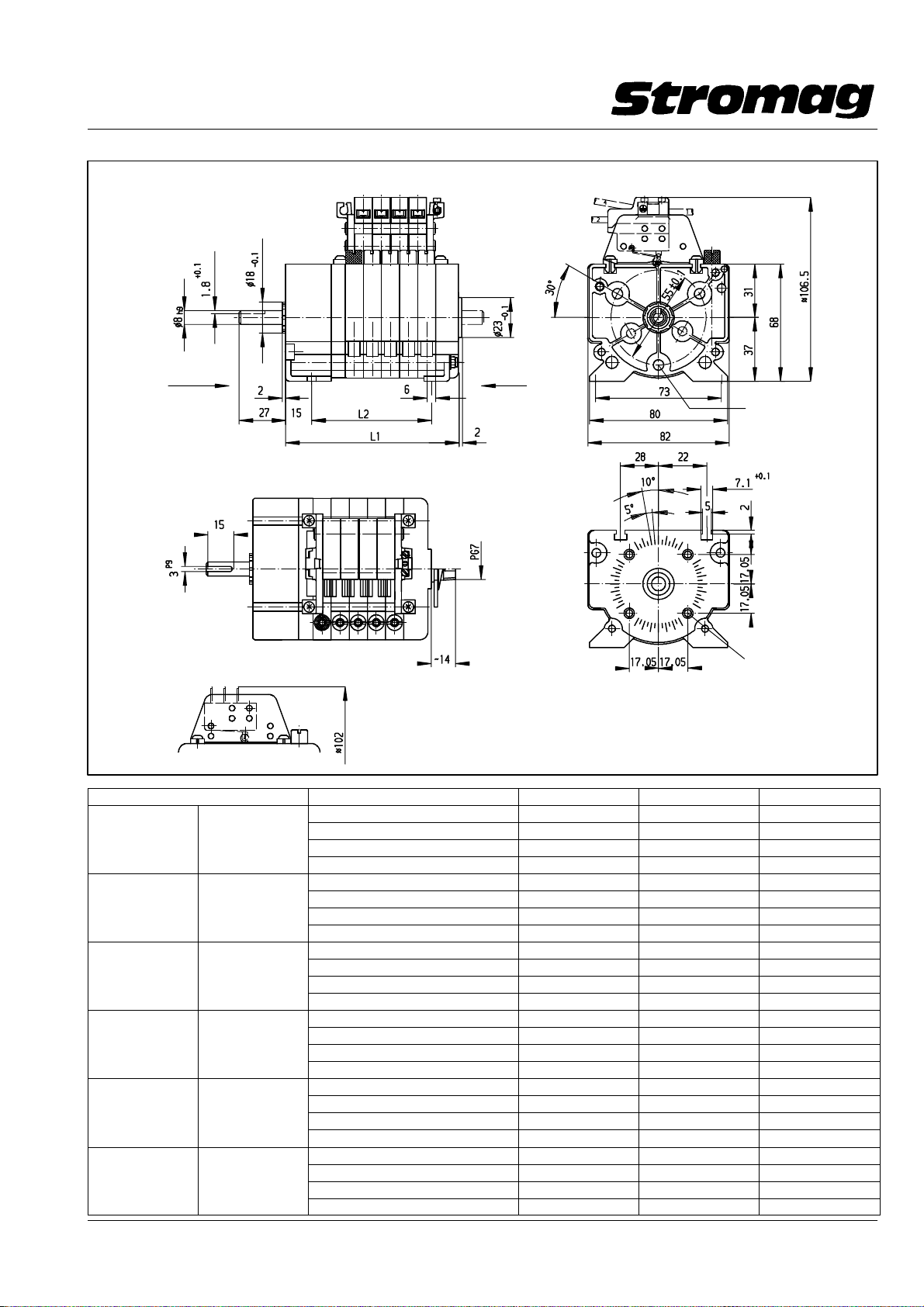
Einbauschalter IP00/IP20
Flush − type switches
Option:
2. Wellenende
2nd shaft end
A − Seite / A − Side
A − Seite / A − Side
Flachstecker − Anschluß/Flat − plug connection
Einbauschalter mit Schraub − (IP20) oder Flachsteckeranschluß IP00
Flush − type switch with screw terminal (IP20) or flat − plug connection (IP00)
Nutzb. Umdrehung/Usable rev. Anzahl Kontakte/No. of contacts Größe/Size Maß/Dim. L1 Maß/Dim. L2
51 51 DZ 2 1A 62,5 32,5
4,1 NM 67 DZM 4 1B 83,5 53,5
6,5 NM 110 DZM 6 1C 104,5 74,5
11 NM 180 DZM 8 1D 125,5 95,5
2 2A 73,0 43,0
17,5 BM 280 DZM 4 2B 94,0 64,0
29 BM 470 DZM 6 2C 115,0 85,0
48 BM 770 DZM 8 2D 136,0 106,0
2 3A 81,5 51,5
75 BM 1200 DZM 4 3B 102,5 72,5
125 BM 2000 DZM 6 3C 123,5 93,5
205 BM 3300 DZM 8 3D 144,5 114,5
2 4A 90,0 60,0
323 BM 5200 DZM 4 4B 111,0 81,0
540 BM 8700 DZM 6 4C 132,0 102,0
880 BM 14200 DZM 8 4D 153,0 123,0
2 5A 98,5 68,5
1384 BM 4 5B 119,5 89,5
2288 BM 6 5C 140,5 110,5
3735 BM 8 5D 161,5 131,5
2 6A 107 77
5900 BM 4 6B 128 98
9800 BM 6 6C 149 119
16000 BM 8 6D 170 140
B − Seite / B − Side
Option:
Anzeigescheibe für
Blockverstellung
Indicating plate for
block adjustment
Poti − Antrieb für Welle
Potentiometer drive
forshaft
dia. 6
M5x6 tief/deep
M3;4 tief /deep
DD140728V
13
Datum / Date 10.2008
Page 15
Getriebe − Nocken − Endschalter Reihe 51 / 51 DZ
Geared Cam Limit Switches Series 51 / 51 DZ
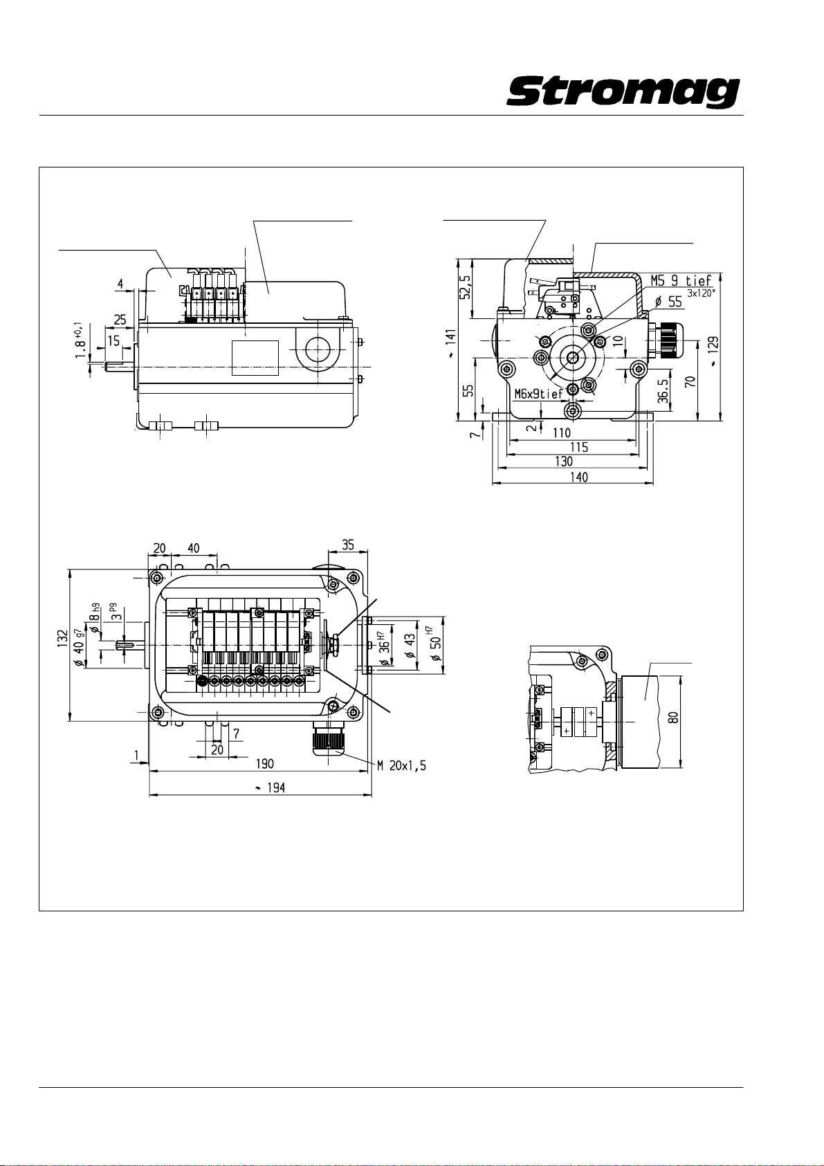
Bauform / Construction B3
Al − Deckel / Cover 168 − 00130
(Option)
Al − Deckel / Cover 168 − 00125
( .MH)
( .MN)
Al − Deckel / Cover 168 − 00125
Al − Deckel / Cover 168 − 00130
(Option)
1.13 Schalter im Aluminium − Gehäuse IP65
(Bauform B3, B3/5)
Merkmale:
Getriebeschalter eingebaut im Aluminium − Gehäuse für den
Einsatz in rauher Umgebung.
Option
Poti − Antrieb für Welle
Potentiometer drive
for shaft
dia. 6
Geberanbau
Encoder assembly
Option
Anzeigescheibe für
Blockverstellung
Indicating plate for
block adjustment
Technische, sowie Maßänderungen vorbehalten
Technical and dimensional modifications reserved
DD140729H
1.13 Switches in aluminium housing IP65
(Type B3, B3/5)
Features:
Geared switch installed in aluminium housing for use in harsh
environments.
Datum / Date 10.2008
14
Page 16
Getriebe − Nocken − Endschalter Reihe 51 / 51 DZ
Geared Cam Limit Switches Series 51 / 51 DZ
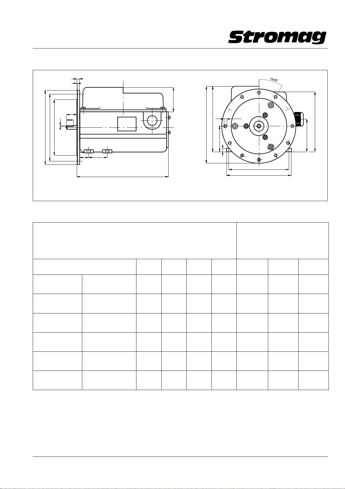
Bauform / Construction B3/B5
6
2
22
+0,1
15
− 0.1
±0.1
1.8
ø160
ø120
ø145
~166
~ 141
55
6.4
~ 129
70
20 40
197
Die Darstellung zeigt die zugänglichen Befestigungsbohrungen
The figure shows the accessible fixing holes
7
Mögliche Baugrößen in Al − Gehäuse IP65 / Possible sizes in aluminium housing IP65
nutzbare Umdrehung / usable rev.
51 51 DZ
4,1 NMN/NMH
6,5 NMN/NMH
11 NMN/NMH
17,5 BMN/BMH
29 BMN/BMH
48 BMN/BMH
75 BMN/BMH
125 BMN/BMH
205 BMN/BMH
323 BMN/BMH
540 BMN/BMH
880 BMN/BMH
67 DZMN/DZMH
110 DZMN/DZMH
180 DZMN/DZMH
280 DZMN/DZMH
470 DZMN/DZMH
770 DZMN/DZMH
1200 DZMN/DZMH
2000 DZMN/DZMH
3300 DZMN/DZMH
5200 DZMN/DZMH
8700 DZMN/DZMH
14200 DZMN/DZMH
2 Kont.
2 Cont.
4 Kont.
4 Cont.
6 Kont.
6 Cont.
8 Kont.
8 Cont.
2 Kont.
2 Cont.
1A 1B 1C 1D
2A 2B 2C 2D 2A 2B 2C
3A 3B 3C 3D 3A 3B 3C
4A 4B 4C 4A 4B 4C
1384 BMN/BMH
2288 BMN/BMH
5A 5B 5C 5A 5B
3735 BMN/BMH
5900 BMN/BMH
9800 BMN/BMH
6A 6B 6A
16000 BMN/BMH
130
140
DD1_40289H
Zusatz / Accessory:
Anzeigenscheibe für
Blockverstellung
(nicht möglich bei Reihe 51 DZ)
Indicating plate for block adj.
(not possible for series 51 DZ)
4 Kont.
4 Cont.
6 Kont.
6 Cont.
Beispiele für Typbezeichnung bei Endschalter Reihe 51 im
Al − Gehäuse IP65
z. B. 48 BMH...= 48 nutzbare Umdrehungen (48BM_),
im 141 mm hohen Al − Gehäuse IP65 (___H_)
11 NMN...= 11 nutzbare Umdrehungen ohne
Blockverstellung (11NM_), im 129 mm hohen
Al − Gehäuse IP65 (___N_)
(Kein Kontaktanschluß mit Flachstecker möglich)
Examples of type designation for 51 series limit switches in
aluminium housing IP 65
e. g. 48 BMH...= 48 usable revolutions (48BM_),
in 141mm high aluminium housing IP65 (__H_)
11 NMN...= 11 usable revolutions without block
adjustment (11NM_), in 129mm high aluminium
housing IP65 (__N_)
(Contact connection with flat plug not possible)
Datum / Date 10.2008
15
Page 17
Getriebe − Nocken − Endschalter Reihe 51 / 51 DZ
g
Geared Cam Limit Switches Series 51 / 51 DZ
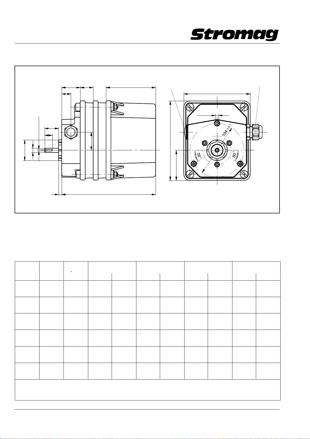
1.14 Kunststoff − Modul − Gehäuse IP66
Bauform B14
25
36
18
+0.1
− 0.1
ø40
h9
ø8
P9
x1.8
3
27
15
M20x1.5
6 L1
35
96
1.14 Plastic module housing IP66
Construction B14
Blindstopfen/Blanking plug
M20 x 1,5
153
59
M6x10
128
tief/deep
M20 x 1,5
DD1_40165V
Merkmale:
Gehäuse aus GF − verstärktem Polycarbonat in Schutzart
IP66.
Modultechnik ermöglicht bestmögliche Raumausnutzung
auch bei Sonderausführungen.
Gesamtlänge durch den Einbau von 25 mm breiten Zwi−
schenstücken nahezu beliebig verlängerbar.
Getriebe−
größe
51 51 DZ
4,1NM
6,5NM
11NM
17,5BM
29BM
48BM
75BM
125BM
205BM
323BM
540BM
880BM
1384BM
2288BM
3735BM
5900BM
9800BM
16000BM
Mehr als 8 Kontakte auf Anfrage möglich / More than 8 contacts on request
Abmessungen bei mehr als 8 Kontakten und bei Sonderausführungen, z. B. Poti, auf Anfrage
Dimensions with more than 8 contacts and with special executions , e.g. potentiometer, on request
Für jedes weitere Zwischenstück sind zu L1 25 mm zu addieren / For any further intermediate piece add 25 mm to L1
67DZM
110DZM
180DZM
280DZM
470DZM
770DZM
1200DZM
2000DZM
3300DZM
5200DZM
8700DZM
14200DZM
Gear size
1 132 0 132 0 132 0 157 1
2 132 0 132 0 157 1 182 2
3 132 0 132 0 157 1 182 2
4 132 0 157 1 182 2 182 2
5 132 0 157 1 182 2 207 3
6 157 1 157 1 182 2 207 3
2 Kontakte/Contacts
A
L1 / mm Anz. Zwst. L1 / mm Anz. Zwst. L1 / mm Anz. Zwst. L1 / mm Anz. Zwst.
Features:
Housing made of glass fibre reinforced polycarbonate with
the degree of protection IP66.
Modular design enables optimal space utilisation also for spe−
cial types.
Overall length can be extended as required with 25mm wide
intermediate pieces.
4 Kontakte/Contacts
B
6 Kontakte/Contacts
C
8 Kontakte/Contacts
D
Datum / Date 10.2008
16
Page 18
Getriebe − Nocken − Endschalter Reihe 51 / 51 DZ
g
Geared Cam Limit Switches Series 51 / 51 DZ
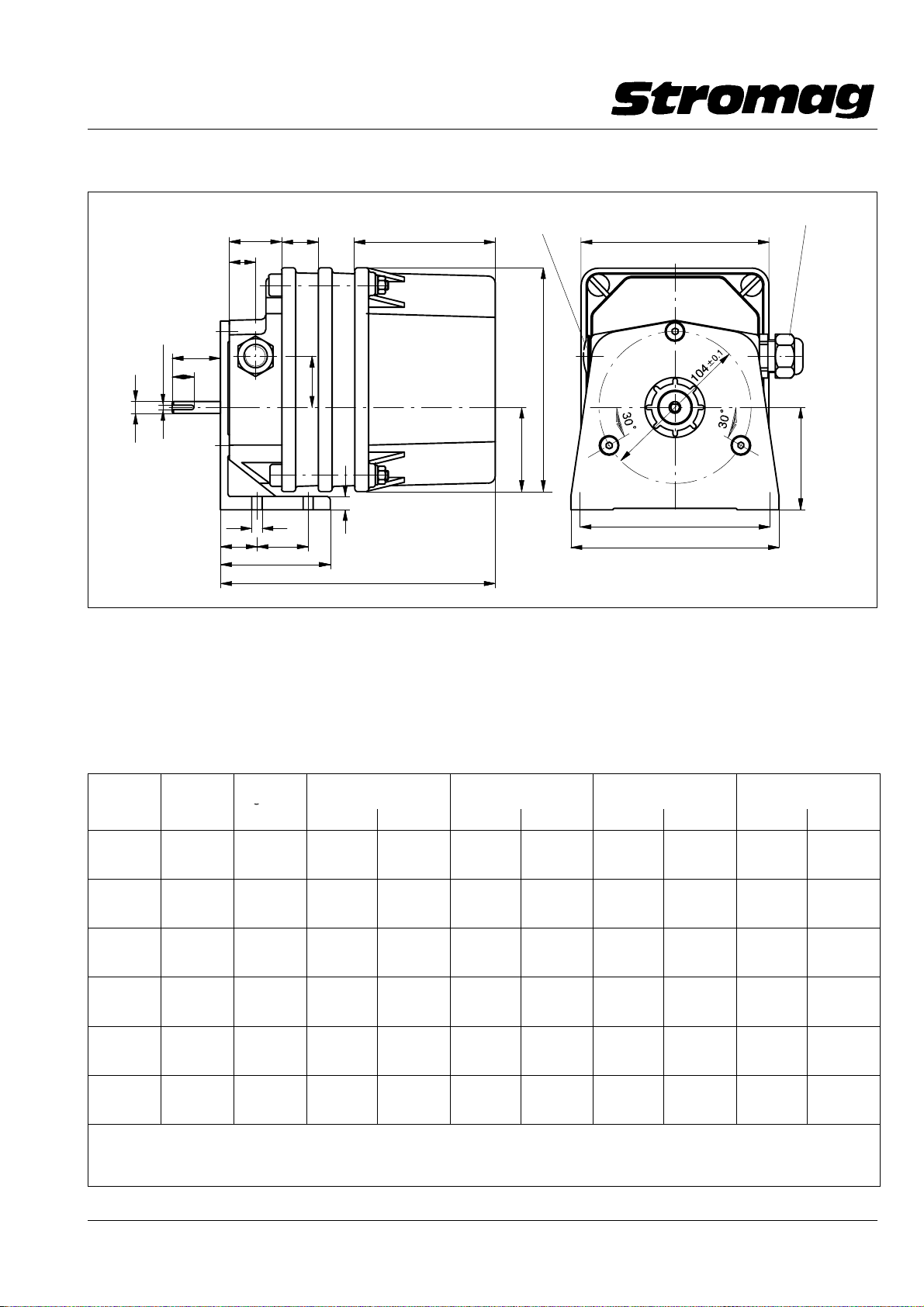
1.15 Kunststoff − Modul − Gehäuse IP66
Bauform B3
36
25
18
+0.1
27
x1.8
15
h9
ø8
P9
3
M20x1.5
7
25
35
35
75
L1
1.15 Plastic module housing IP66
Construction B3
Blindstopfen/Blanking plug
96
9
M20x1.5
153
59
128
130
145
M20x1.5
70
DD1 40164V
Merkmale:
Gehäuse aus GF − verstärktem Polycarbonat in Schutzart
IP66.
Modultechnik ermöglicht bestmögliche Raumausnutzung
auch bei Sonderausführungen.
Gesamtlänge durch den Einbau von 25 mm breiten Zwi−
schenstücken nahezu beliebig verlängerbar.
Getriebe−
größe
51 51 DZ
4,1NM
6,5NM
11NM
17,5BM
29BM
48BM
75BM
125BM
205BM
323BM
540BM
880BM
1384BM
2288BM
3735BM
5900BM
9800BM
16000BM
Mehr als 8 Kontakte auf Anfrage möglich / More than 8 contacts on request
Abmessungen bei mehr als 8 Kontakten und bei Sonderausführungen, z. B. Poti, auf Anfrage
Dimensions with more than 8 contacts and with special executions , e.g. potentiometer, on request
Für jedes weitere Zwischenstück sind zu L1 25 mm zu addieren / For any further intermediate piece add 25 mm to L1
67DZM
110DZM
180DZM
280DZM
470DZM
770DZM
1200DZM
2000DZM
3300DZM
5200DZM
8700DZM
14200DZM
Gear size
1 138 0 138 0 138 0 163 1
2 138 0 138 0 163 1 188 2
3 138 0 138 0 163 1 188 2
4 138 0 163 1 188 2 188 2
5 138 0 163 1 188 2 213 3
6 163 1 163 1 188 2 213 3
2 Kontakte/Contacts
A
L1 / mm Anz. Zwst. L1 / mm Anz. Zwst. L1 / mm Anz. Zwst. L1 / mm Anz. Zwst.
Features:
Housing made of glass fibre reinforced polycarbonate with
the degree of protection IP66.
Modular design enables optimal space utilisation also for spe−
cial types.
Overall length can be extended as required with 25mm wide
intermediate pieces.
4 Kontakte/Contacts
B
6 Kontakte/Contacts
C
8 Kontakte/Contacts
D
Datum / Date 10.2008
17
Page 19
Getriebe − Nocken − Endschalter Reihe 51 / 51 DZ
g
Geared Cam Limit Switches Series 51 / 51 DZ
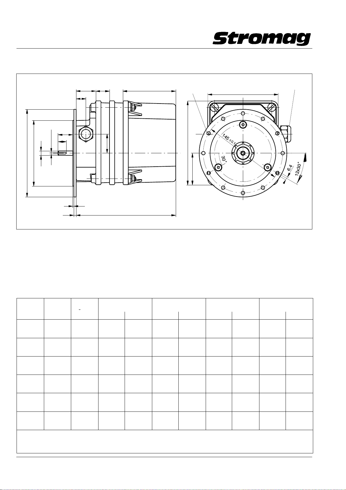
1.16 Modul − Gehäuse IP66
Bauform B5
+0.1
27
x1.8
15
P9
− 0.1
3
h9
ø120
ø160
ø8
4
36
18
M20x1.5
2
25
35
L1
96
1.16 Module housing IP66
Construction B5
Blindstopfen/Blanking plug
M20x1.5
153
59
128
M20x1.5
DD1_40163V
Merkmale:
Gehäuse aus GF − verstärktem Polycarbonat in Schutzart
IP66.
Modultechnik ermöglicht bestmögliche Raumausnutzung
auch bei Sonderausführungen.
Gesamtlänge durch den Einbau von 25 mm breiten Zwi−
schenstücken nahezu beliebig verlängerbar.
Getriebe−
größe
51 51 DZ
4,1NM
6,5NM
11NM
17,5BM
29BM
48BM
75BM
125BM
205BM
323BM
540BM
880BM
1384BM
2288BM
3735BM
5900BM
9800BM
16000BM
Mehr als 8 Kontakte auf Anfrage möglich / More than 8 contacts on request
Abmessungen bei mehr als 8 Kontakten und bei Sonderausführungen, z. B. Poti, auf Anfrage
Dimensions with more than 8 contacts and with special executions , e.g. potentiometer, on request
Für jedes weitere Zwischenstück sind zu L1 25 mm zu addieren / For any further intermediate piece add 25 mm to L1
67DZM
110DZM
180DZM
280DZM
470DZM
770DZM
1200DZM
2000DZM
3300DZM
5200DZM
8700DZM
14200DZM
Gear size
1 132 0 132 0 132 0 157 1
2 132 0 132 0 157 1 182 2
3 132 0 132 0 157 1 182 2
4 132 0 157 1 182 2 182 2
5 132 0 157 1 182 2 207 3
6 157 1 157 1 182 2 207 3
2 Kontakte/Contacts
A
L1 / mm Anz. Zwst. L1 / mm Anz. Zwst. L1 / mm Anz. Zwst. L1 / mm Anz. Zwst.
Features:
Housing made of glass fibre reinforced polycarbonate with
the degree of protection IP66.
Modular design enables optimal space utilisation also for spe−
cial types.
Overall length can be extended as required with 25mm wide
intermediate pieces.
4 Kontakte/Contacts
B
6 Kontakte/Contacts
C
8 Kontakte/Contacts
D
Datum / Date 10.2008
18
Page 20
Getriebe − Nocken − Endschalter Reihe 51 / 51 DZ
g
Geared Cam Limit Switches Series 51 / 51 DZ
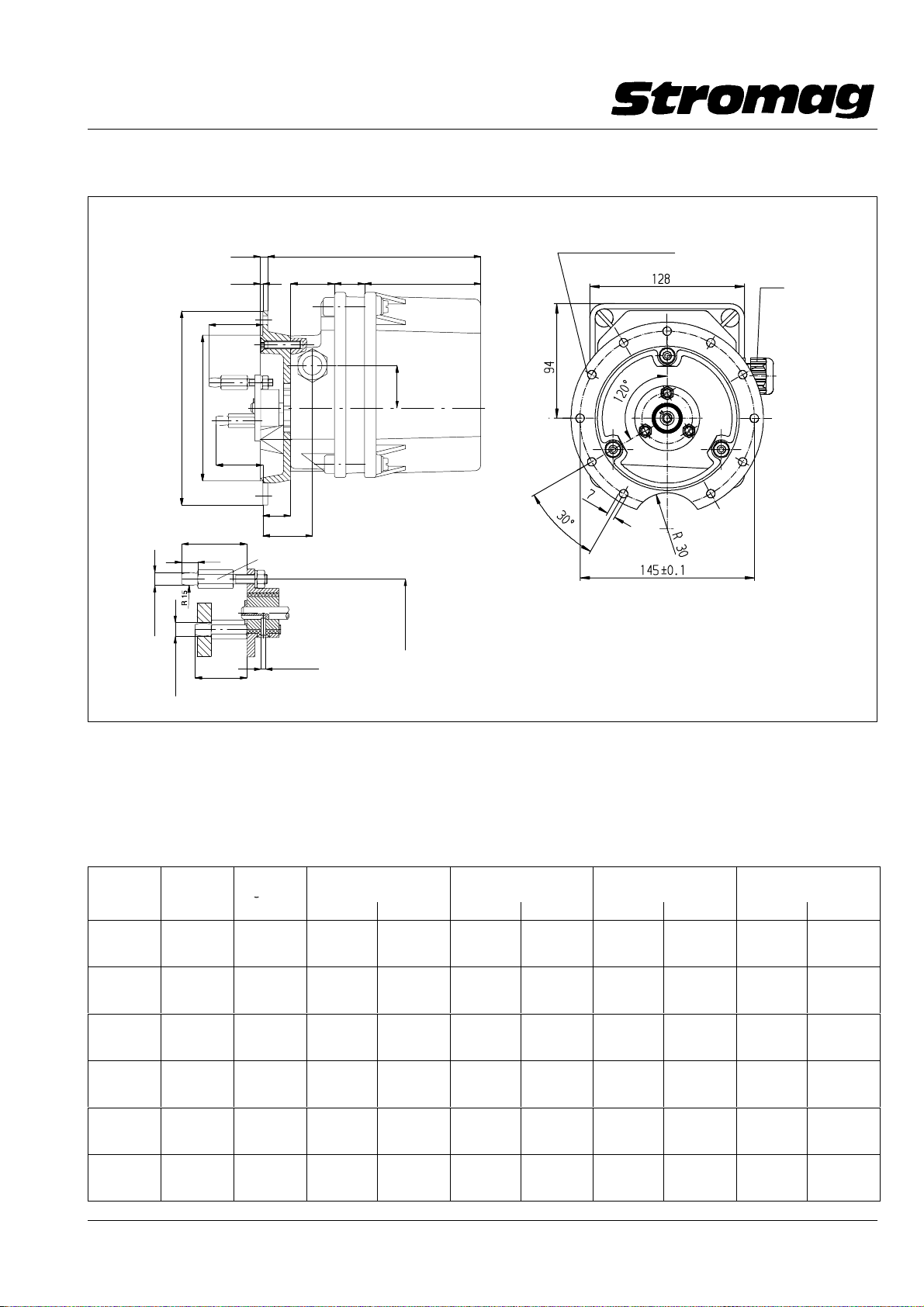
1.17 Modul − Gehäuse IP66
Bauform B5 Zollern − Winde"
6
2
46.5
max.
− 0.1
ø 160
ø 120
38.5
min.
23
40
max.
10
− 0.05
ø 8
+0.5
ø 8.5
6Kt 10
32
min.
36L125 96
41
3x Mitnehmer auf 120°
ø 3
35
ø 42 ±0.2
1.17 Module housing IP66
Construction B5 Zollern winch"
Blindstopfen/Blanking plug M20x1.5
M20x1.5
B5 − Anbauflansch für Zollern − Winde / B5 − flange for Zollern Winch
168 − 01517
Elast. Antriebsflansch / flexible drive flange
F + M 167 − 02780
max. zulässige Betriebsdrehzahl / max. adm. speed
n = 1000 min−1 / rpm
Verdrehwinkel bei / twisting angle at 5 Nm = 5 ± 0.5_
DD1_40414H
Merkmale:
Gehäuse aus GF − verstärktem Polycarbonat in Schutzart
IP66.
Modultechnik ermöglicht bestmögliche Raumausnutzung
auch bei Sonderausführungen.
Gesamtlänge durch den Einbau von 25 mm breiten Zwi−
schenstücken nahezu beliebig verlängerbar.
51 51DZ
4,1NM
6,5NM
11NM
17,5BM
29BM
48BM
75BM
125BM
205BM
323BM
540BM
880BM
1384BM
2288BM
3735BM
5900BM
9800BM
16000BM
67DZM
110DZM
180DZM
280DZM
470DZM
770DZM
1200DZM
2000DZM
3300DZM
5200DZM
8700DZM
14200DZM
Getriebe−
größe
Gear size
1 151 0 151 0 151 0 176 1
2 151 0 151 0 176 1 201 2
3 151 0 151 0 176 1 201 2
4 151 0 176 1 201 2 201 2
5 151 0 176 1 201 2 226 3
6 151 1 176 1 201 2 226 3
2 Kontakte/Contacts
A
L1 / mm Anz. Zwst. L1 / mm Anz. Zwst. L1 / mm Anz. Zwst. L1 / mm Anz. Zwst.
Features:
Housing made of glass fibre reinforced polycarbonate with
the degree of protection IP66.
Modular design enables optimal space utilisation also for spe−
cial types.
Overall length can be extended as required with 25mm wide
intermediate pieces.
4 Kontakte/Contacts
B
6 Kontakte/Contacts
C
8 Kontakte/Contacts
D
Datum / Date 10.2008
19
Page 21
Getriebe − Nocken − Endschalter Reihe 51 / 51 DZ
Geared Cam Limit Switches Series 51 / 51 DZ
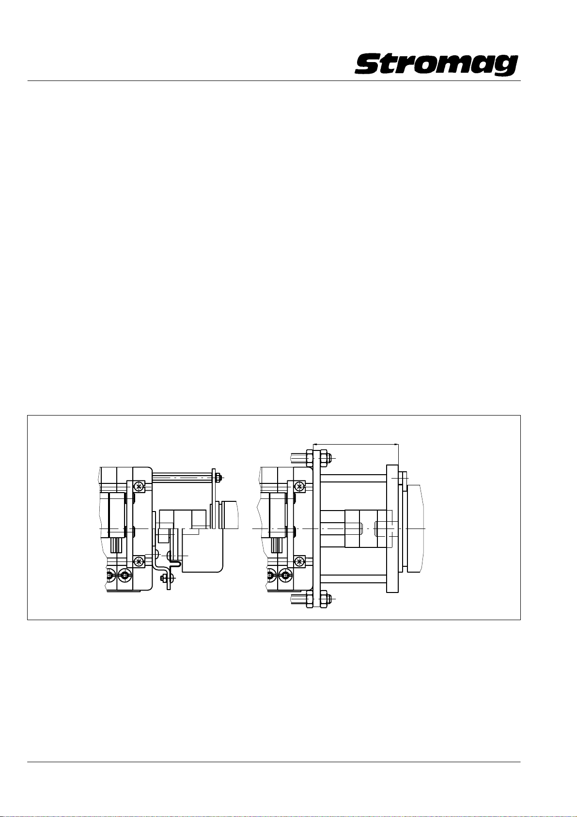
2 Sonderausführungen
2.1 Durchgeführte Antriebswelle
Bedingt durch die Konstruktion der Getriebe − Nocken − End−
schalter der Reihen 51 und 51 DZ wird die Antriebswelle
durch den Schalter geführt. Sie schließt normalerweise mit
dem Modulhinterteil ab.
Gegen Mehrpreis wird auf Wunsch die Antriebswelle verlän−
gert (Sonderwelle).
Synchron zur Antriebswelle können damit Inkremental − und
Absolut − Encoder zur digitalen Stellungsrückmeldung ange−
trieben werden. Auch Tachogeneratoren werden direkt von
der Antriebswelle angetrieben.
Je nach Gewicht des anzubauenden Gebers sind unter−
schiedliche Anbaukonstruktionen möglich.
Hohlwellengeber werden direkt auf die Welle aufgesteckt und
das Gehäuse über eine Drehmomentenstütze gehalten.
Geber mit Zapfenwelle bis zu einem Gewicht von ca. 250 g
und bei Einsatzfällen ohne Vibrationen und Schläge werden
über ein leichtes Halteblech angebaut.
Geber mit Zapfenwelle ab einem Gewicht von ca. 250 g oder
für den Einsatz unter erschwerten Bedingungen werden über
einen Adapterflansch mit einer zusätzlichen Verstärkung an−
gebaut.
Für die konstruktive Überprüfung der Einbausituation benöti−
gen wir verbindliche Maß − und Gewichtsangaben der An−
bauteile.
Zusätzlich eingebaute Teile vergrößern unter Umständen die
Baulänge der Getriebe − Schalter.
2 Special executions
2.1 Inserted drive shaft
On account of the design of 51 and 51 DZ series geared cam
limit switches, the drive shaft is inserted through the switch
and normally terminates flush with the rear part of the mo−
dule.
The drive shaft can be extended at an additional charge (spe−
cial shaft) on request.
As a result, incremental and absolute encoders can be driven
synchronous with the drive shaft for digital position feedback.
Also tachogenerators can be directly driven by the drive shaft.
In relation to the weight of the encoder to be fitted, various
mounting executions are possible.
Hollow shaft encoders are directly slipped on the shaft and
the housing is held by a torque support.
Encoders with power take − off shaft up to a weight of approx.
250 g and for vibration − free and shock − free applications are
mounted through a light holding sheet.
Encoders with power take − off shaft having a weight of more
than approx. 250 g or being intended for application under
heavy conditions, are mounted via an adapter flange with ad−
ditional reinforcement
For constructional examination of the mounting situation, we
require binding data on the dimensions and weights of the
mounting components.
Additional mounted parts may increase the overall length of
the gearing.
Geber − Anbau am 2.Wellenende für leichte Geber
Sensor mounted in second shaft end for light encoders
Geber − Anbau mit Kupplung
Sensor mounted with coupling
Anbau eines Hohlwellengebers
Mounting a hollow shaft encoder
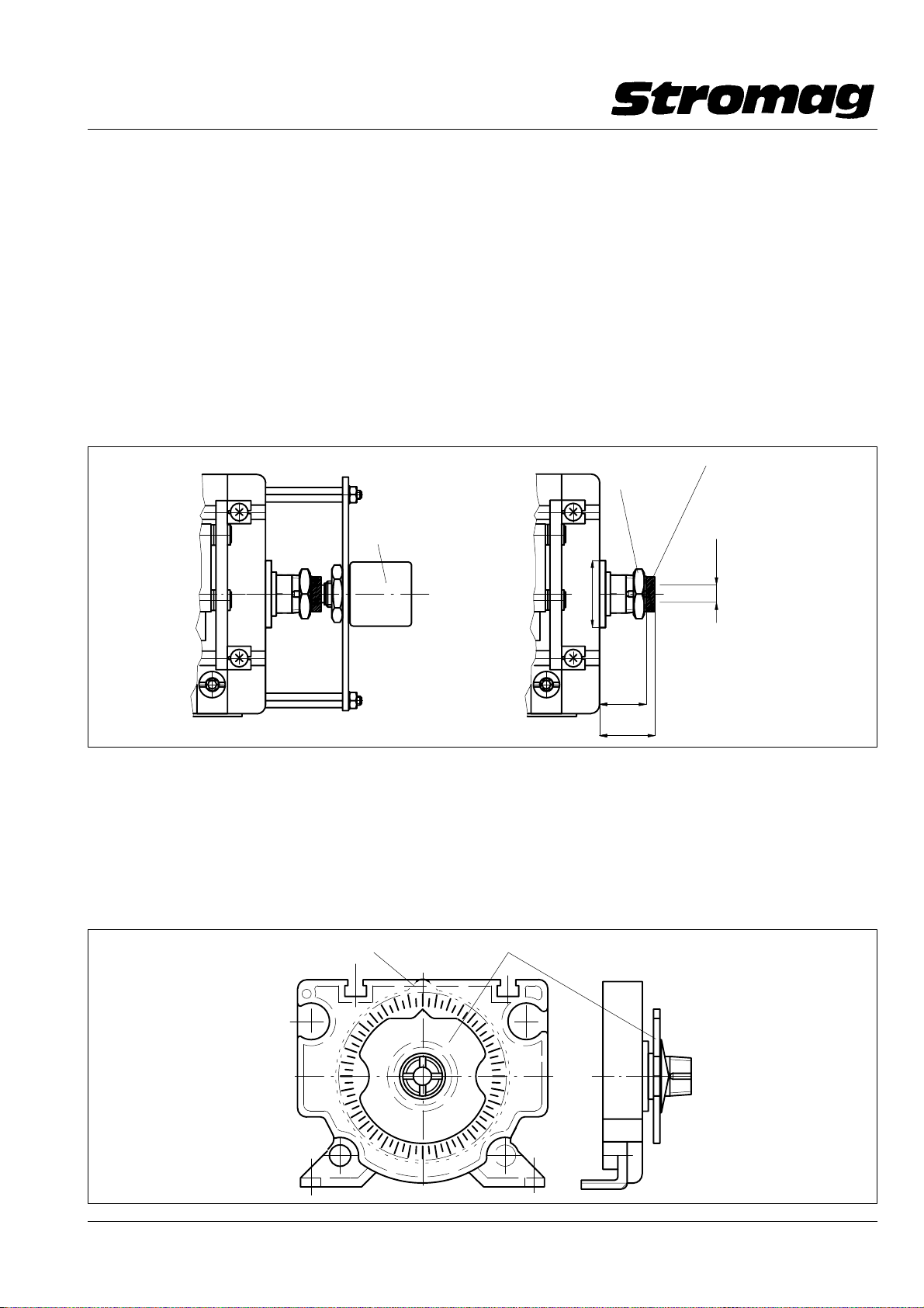
2.2 Potentiometerantrieb (nur bei Reihe 51 möglich)
Für den Antrieb von Drehwiderständen zur analogen Stel−
lungsrückmeldung stehen 2 Ausführungen zur Verfügung. Sie
sind konstruktiv gleich ausgeführt und für die Aufnahme von
Potentiometerwellen mit einem Durchmesser von 6 mm sowie
für ein max. Drehmoment von 10 Ncm vorgesehen.
a) Potikupplung "N"
Die Kupplung dreht synchron mit den Nockenscheiben.
Der nutzbare Drehwinkel für die Potentiometer ist max.
345_.
Adapterflansch für schwere Geber
Adapter flange for heavy encoders
57
DD1_40465H
2.2 Potentiometer drive (only possible for series 51)
Available are two types for driving potentiometers for ana −
logue position feedback. They are identical in design and are
able to accept two potentiometer shafts with a diameter of
6 mm and a max. torque of 10 Ncm.
a) Potentiometer coupling "N"
This coupling turns synchronous with the cam disc. The
usable angle of rotation for the potentiometer is maximum
345_.
Datum / Date 10.2008
20
Page 22
Getriebe − Nocken − Endschalter Reihe 51 / 51 DZ
Geared Cam Limit Switches Series 51 / 51 DZ
Beim Einsatz einer zusätzlichen Nockenscheibengruppe
(verlängert den Schalter um 10,5 mm) kann die Einstel−
lung des Potentiometers mit der letzten Verstellschnecke
ohne das Lösen von Schrauben und Muttern erfolgen. Die
Poti − Einstellung mit zusätzlicher Nockenscheibengruppe
kann nur in Ausführung "N" erfolgen.
b) Potikupplung "S"
Die Kupplung dreht synchron mit der Eingangsdrehzahl
der Nockenscheibengruppe. Der nutzbare Drehwinkel für
die Potentiometer ist max. 1470_ (345_x4,285). Für diese
Drehwinkel werden üblicherweise Mehrfach − Wendel −
Potentiometer eingesetzt.
Zusätzlich eingebaute Potentiometer vergrößern unter Um−
ständen die Baulänge der Getriebe − Schalter. Für die Angabe
der genauen Baulänge bitten wir um Rückfrage, evtl. unter
Angabe der Potentiometermaße.
Beispiel für Potianbau/Example of potentiometer mounting
Potentiometer
When fitting an additional cam disc assy (extends the
switch by 10.5 mm), the potentiometer can be adjusted
by the last adjusting worm without having to lose the
screws and nuts. The potentiometer adjustment with addi−
tional cam disc assy is possible with execution "N" only.
b) Potentiometer coupling "S"
This coupling turns synchronous with the input speed of
the cam disc group. The usable angle of rotation for the
potentiometer is maximum 1470_ (345_x4.285). For this
angle of rotation, multi − turn potentiometers are normally
used.
Additionally installed potentiometers may increase the overall
length of the geared switch.
For the exact overall length please consult us stating the po−
tentiometer dimensions.
Klemm − Mutter PG 7
Clamping nut
(SW 15)
ø 23
Gummieinsatz
Rubber insert
Mdmax. = 10 Ncm
ø 6
DD1_40288V
2.3 Anzeigescheibe (nur bei Reihe 51 möglich)
Die Anzeigescheibe zur Blockverstellung (auf Wunsch gegen
Mehrpreis lieferbar) dient dazu, die Verstellung der Schalter
mittels Blockverstellung zu erleichtern. Die durch Reibschluß
gehaltene Anzeigescheibe wird auf eine Referenzmarke ein−
gestellt und erleichtert dadurch den späteren Abgleich auf
diese Referenzmarke mittels der Blockverstellschnecke we−
sentlich. Unter Umständen wird durch die Anzeigescheibe ein
zusätzliches Gehäuse − Zwischenstück nötig.
Nockenscheibe / Cam disc
~16
Aufnahmebohrung für Potiwelle
Locating hole for potentiometer shaft
~19
DD1_40290V
2.3 Indicating plate (only possible for series 51)
The indicating plate for block adjustment (available at an ad−
ditional charge on request) serves to facilitate adjustment of
the switch by means of block adjustment. The friction locked
indicating plate is set at a reference mark which thus conside−
rably facilitates subsequent adjustment to this reference mark
by means of the block adjusting worm. The use of the indica−
ting plate may make an additional housing intermediate piece
necessary.
Anzeigescheibe / Indicating plate
21
DD1_40291V
Datum / Date 10.2008
Page 23
Getriebe − Nocken − Endschalter Reihe 51 / 51 DZ
Geared Cam Limit Switches Series 51 / 51 DZ
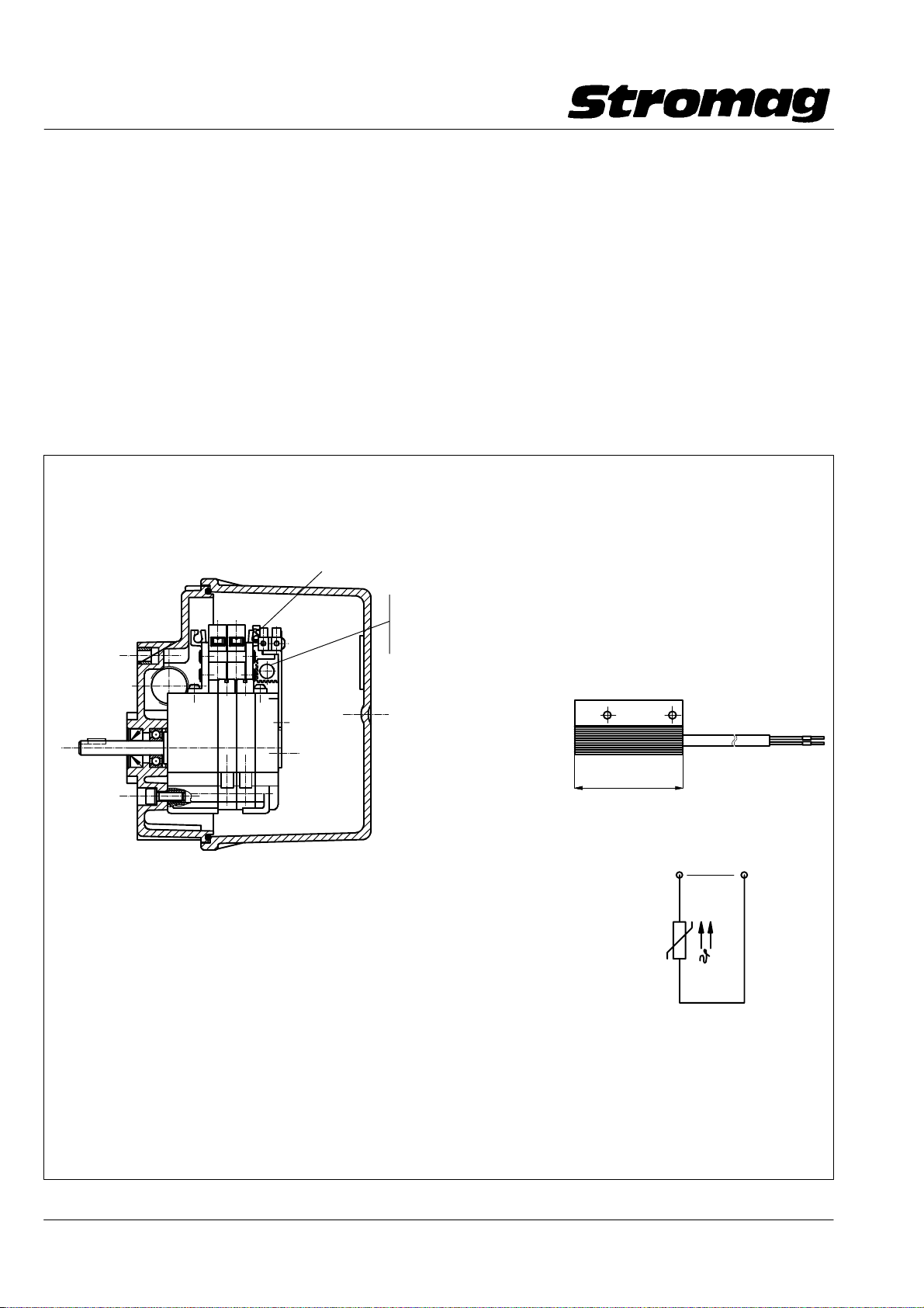
2.4 Stillstandsheizung
Der Innenraum der Getriebeschalter ist ein elektrischer Be−
triebsraum genau wie ein Schaltschrank. Es sollten bei ex−
trem niedrigen Außentemperaturen oder bei extrem wech−
selnden Temperaturen bei einer feuchten Umgebungs −
atmosphäre Vorkehrungen gegen Kondenswasser im Schal−
ter getroffen werden.
Die speziell für die Getriebe − Endschalter entwickelten gere−
gelten Stillstandsheizungen verhindern wirkungsvoll Kon−
denswasser und zu niedrige Temperaturen im Schalter. Es
gibt sie in 2 Ausführungen, die sich nur in der zulässigen An−
schlußspannung unterscheiden. Der Einbau der Stillstands−
heizung verlängert nicht die Einbaulänge der Schalter. Sie
sind in jede Schalterausführung einbaubar. Sie können auch
nachgerüstet werden.
Beispiel für den Einbau einer PTC − Heizung in ein IP66 Gehäuse
Example of installation of a PTC heater in an IP66 housing
Anschlußklemme/Connection terminal
PTC − Heizungsgruppe/PTC heater assembly
für/for 12 − 36V AC/DC, P ca./approx. 2.5 Watt
oder/or 110 − 250V AC/DC, P ca./approx. 4 Watt
2.4 Anti − condensation heater
The interior space of the geared switch is an electrical opera−
ting area just like a switchgear cabinet. Precautions should be
taken to prevent condensation from forming inside the switch
at extremely low outside temperatures or extreme changes of
temperature in a damp atmosphere.
These controlled, anti − condensation heaters, which have
been specially developed for use with our geared limit swit−
ches, effectively prevent condensation and excessively low
temperatures in the switches. They are available in two ver−
sions and differ only by the permissible supply voltage. The
anti − condensation heater, which can be installed in any
switch version, will not increase the overall length of the swit−
ches and can also be retrofitted.
DD1_40285V
Ausführung/Execution: U
Heizleistung/Heating cap.: ca. 2.5 Watt ca. 4 Watt
(im ausgeregelten Zustand/in levelled condition)
Kaltwiderstand PTC (bei 25_C)
Cold resistance PTC: R25 20 ± 35% R25 1500 ± 35%
PTC − Bezugstemperatur:
PTC ref. temperature: 50_ C50_C
Schutzklasse
Protection (VDE 0100, 0160): II II
Anschlußleitung: 2x0.25mm2, Silikonkabel 2x0.25mm2, Silikonkabel
Connection cable: 2x0.25mm2, Siliconecable 2x0.25mm2, Siliconecable
Heizkörper/Radiator: Aluminium eloxiert/eloxed Aluminium eloxiert/eloxed
Gewicht / Weight: ca. 40 g ca 40 g
12 − 36V AC/DC 110 − 250V AC/DC
B
PTC − Heizung/Heater
50
Ersatzschaltbild
Equivalent wiring diagram
12
*
U
B
PTC
*Anschlußspannung je nach ver −
wendeter Variante 12 − 36V AC/DC
bzw. 110 − 250V AC/DC
Connection voltage in relation to the
variant used 12 − 36V AC/DC
or 110 − 250V AC/DC
Datum / Date 10.2008
DD1_ 40298V
22
Page 24
Getriebe − Nocken − Endschalter Reihe 51 / 51 DZ
Geared Cam Limit Switches Series 51 / 51 DZ
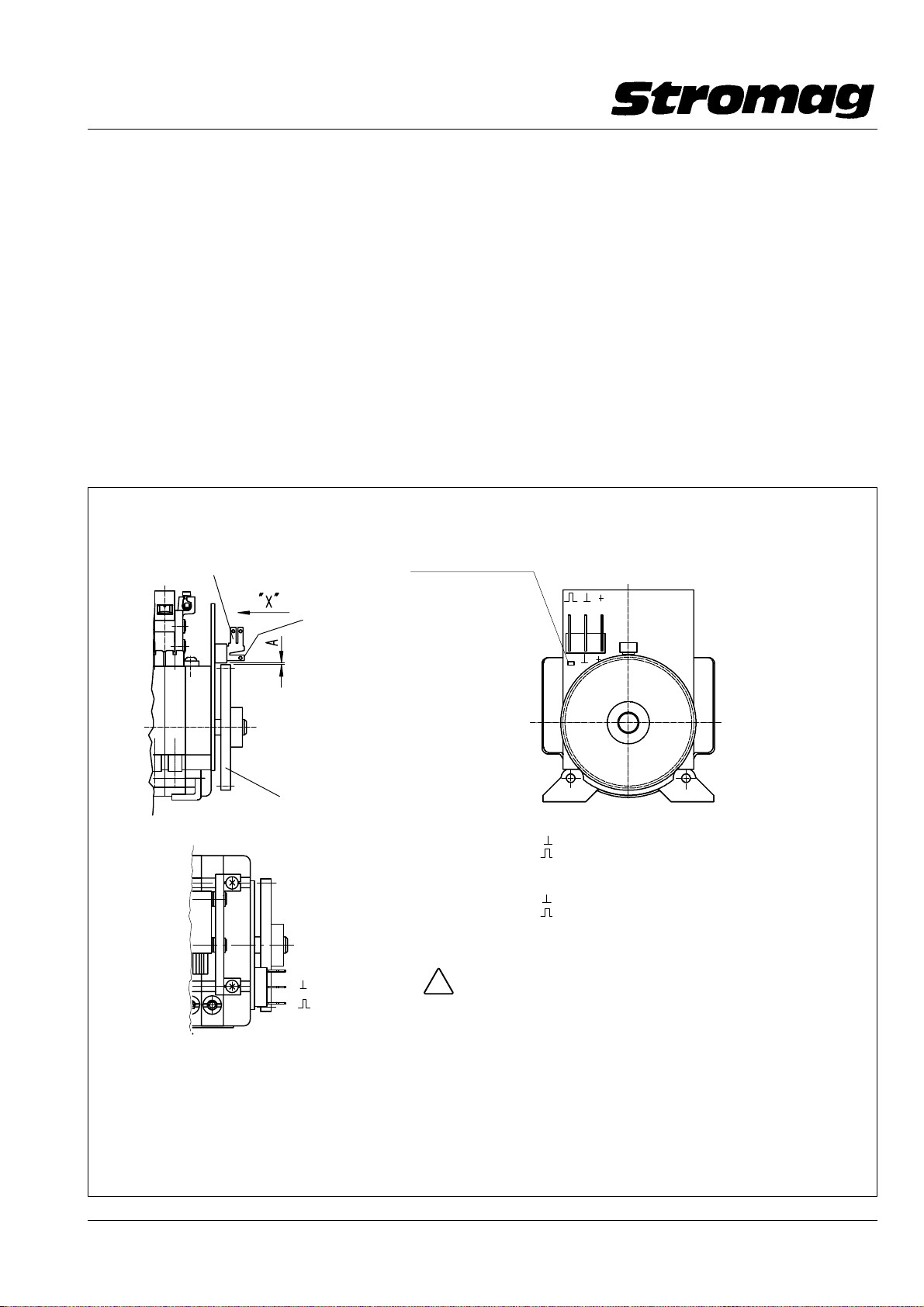
2.5 Impulsgeber I 49
Speziell für den Einsatz in Mobilkranen wurde ein Impulsge−
ber mit besonderen technischen Eigenschaften entwickelt. Es
wird magnetisch ein Zahnrad mit 50 Zähnen abgetastet (50
Impulse/Umdrehung). Die Elektronik ist für den Betrieb in ei−
nem Fahrzeug − Bordnetz vorgesehen und ist besonders ge−
schützt gegen die in diesen Netzen auftretenden Überspan−
nungen. Der Versorgungsspannungs − Anschluß ist ver −
polungssicher. Der einkanalige Impulsgeberausgang kann in−
duktive Lasten bis zu einem Strom von ca. mittl. 110 mA trei−
ben und er ist kurzschlußfest. Um eine zu starke Erwärmung
der anzuschließenden Hubmagnetspulen bei einem Dauersi−
gnal zu verhindern, schaltet der Ausgangsverstärker jeden
Impuls nach ca. 20 ms aus (Monoflop − Funktion).
Mit diesem Impulsgeber wird eine Drehung des Endschalters
angezeigt und es kann die Geschwindigkeit erkannt werden.
Eine Erkennung der Rechts − und Linksdrehrichtung ist nicht
möglich.
Impulsgeber mit 50 Impulsen/Umdrehung für Endschalter der Reihe 51 zur Montage an der B − Seite des Schalters
Pulse generator with 50 pulses/rev. fitted to the B − side of the limit switch
Flachstecker/Flat plug 6.3 mm x 0.8
LED als Funktionskontrolle
LED as performance check
2.5 Pulse transmitter I 49
This pulse transmitter has been specially developed for use
in mobile cranes and has special technical features. A toothed
wheel with 50 teeth is magnetically scanned (50 pulse/revolu−
tion). The electronic circuitry is designed for operation in a
motor vehicle supply system and is specially protected
against the overvoltages occurring on these systems. The
supply voltage connection is protected against polarity rever−
sal. The single channel pulse transmitter output can drive in−
ductive loads up to a current of on average approx. 110 mA
and is short − circuit proof. To prevent excessive heating of the
solenoid coils to be connected, with a continuous signal, the
output amplifier disconnects each pulse after about 20 ms
(monoflop function).
With this pulse transmitter, rotation of the limit switch is indica−
ted and the speed can be identified. It is not possible to di−
stinguish between clockwise and counter − clockwise rotation.
Ansicht / View "X"
DD1 40565H
Flachstecker/Flat plug 2.8 mm x 0.8
Meßabstand/Measuring distance A X 0.2 mm
Zahnrad mit 50 Zähnen
Toothed wheel with 50 teeth
+ 24V =
Ground
Output
Technische Daten / Technical data
Betriebsspannung/Service voltage 24V DC (18 − 36V DC)
Stromaufnahme/P ower consumption ca./approx. 180 mA
Ausgang/Output mittl./on average 110 mA
Impulsdauer/Pulse duration ca./approx. 20 ms (Monoflopfunktion/monoflop function)
Temperaturbereich/T emperature range − 40°C bis/to +85°C
− Kurzschlußfester Ausgang / Output short circuit proof
− Versorgungsspannung verpolungssicher / Supply voltage protected against exchange of poles
− Funtionskontrolle mittel gelber Leuchte / Performance check by yellow LED
− 50 Impulse/Umdrehung; Pulses/rev.
− keine Abgleich − und Einstellarbeiten / no aligning and adjusting works
− Anschluß über Flachstecker / Connection through flat plug 6.3 mm x 0.8
Achtung / Caution
Falscher Anschluß kann zu Zerstörung führen!
!
wrong connection can cause destruction!
Anschlüsse:
+24V= − Versorgungsspg. +18V − +36V DC
Ground − Masse
Output − Ausgangimpuls
Connections:
+24v= − supply voltage +18V to +36V d.c
Ground − GND
Output − output signal
23
Datum / Date 10.2008
Page 25
Getriebe − Nocken − Endschalter Reihe 51 / 51 DZ
Geared Cam Limit Switches Series 51 / 51 DZ
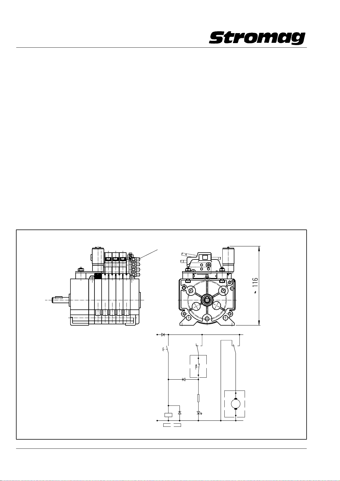
2.6 Motorische Blockverstellung (nur bei Reihe 51)
Durch die Möglichkeit, alle Kontakte mit einer einzigen Ver−
stellschnecke zu verstellen, bietet sich die Möglichkeit, diese
Verstellung mittels eines kleinen Getriebe − Motors zu auto −
matisieren. Einer der eingebauten Schaltkontakte wird dabei
zur Abschaltung des Verstellmotors verwendet. Damit lassen
sich nach einer Verstellung des Antriebssystemes und einer
anschließenden Referenzfahrt alle Kontakte wieder in eine
vorbestimmte Position zu diesem Motorabschaltkontakt brin−
gen. Eingesetzt werden kann dieses System z. B. nach einem
Seilwechsel bei Kranen und Schrappern. Nach dem Seil−
wechsel wird das Lastaufnahmemittel per Hand in eine vorge−
gebene Position gefahren. Durch Knopfdruck wird der Ver−
stellvorgang gestartet. Sobald die Nockenscheibe den
Motorabschaltkontakt (Selbsthaltung der Verstellung) betätigt,
wird der Verstellvorgang gestoppt. Alle Abschaltpunkte der
Maschine stehen jetzt wieder in dem vorherigen Verhältnis
zum Referenzpunkt. Auch mit der Potikupplung "N" ange−
baute Potentiometer werden mitverstellt, siehe dazu Einbau−
bild und Schaltungsvorschlag.
Dieses System kann auch in verstellbaren Punktzügen von
bühnentechnischen Einrichtungen eingesetzt werden. Dabei
ist zu beachten, daß durch die Verstellung der Nockenschei−
ben die Antriebswelle, und damit evtl. dort angebaute Enco−
der, nicht mit verstellt werden.
Dieser ist gesondert nachzujustieren.
2.6 Motor − driven block adjustment (only for series 51)
The possibility to adjust all contacts with a single adjusting
worm offers the option of automating this adjustment by
means of a small geared motor. One of the switching contacts
provided is used for disconnection of the adjusting motor. Af−
ter adjustment of the drive system and subsequent reference
operation, all contacts can be reset to a predetermined posi−
tion with respect to this motor disconnecting contact. This sy−
stem can be used, e.g. after a rope change for cranes and
scrapers. After the rope change, the lifting appliance is moved
into a predetermined position manually. Adjustment can be
initiated by pressing a button. Adjustment is stopped as soon
as the cam disc actuates the cam disc of the motor discon−
necting contact (self − holding of adjustment). All disconnec−
ting points of the machine are now placed in their previous
relation to the reference point. Potentiometers with the poten−
tiometer coupling "N" are also adjusted, see installation dia−
gram and circuit suggestion.
This system is also suitable for use in adjustable stage machi−
nery, whereby it is important to ensure that the drive shaft and
in turn a possibly installed encoder is not affected through
adjustment of the cam discs.
The encoder has to be re − adjusted separately.
Technische Daten / Technical data:
Anschlußspannung (Motor)
Supply voltage (motor) 24V DC
Stromaufnahme (Motor)
Current consumption (motor) ca. 200mA
Anschlußwiderstand
Connection resistance 65 Ohm
max. Verstellzeit
max. adjustment time ca.90 sek.
Klemmleiste/Terminal strip − X1
V1
+ 24V
1N4007
S1
V2
1N4007
−A1
−A2
V3
1N4007
K1
0 V
DD1_40292V
K1K1
S2
− X1.1
− X1.2
M1
R1
1k
V3
LED
im Endschalter eingebaut / mounted into the limit switch
− X1.3
M
− X1.4
Datum / Date 10.2008
DD1_40296V
24
Page 26

Bühnentechnik / Stage technology
Getriebe − Nocken − Endschalter Reihe 51 / 51 DZ
Geared Cam Limit Switches Series 51 / 51 DZ
3 Getriebe − Nocken − Endschalter Reihe 51
Ausführung für erhöhte Anforderungen nach BGV C1
(VBG 70) (Bühnentechnik)
3.1 Allgemeines
Die gesamte moderne Bühnentechnik, mit den für diesen Be−
reich speziell entwickelten Hebezeugen, ist ein typischer Ein−
satzfall für Getriebe − Nocken− Endschalter. Bei normalen He−
bezeugen ist der Aufenthalt unter schwebenden Lasten
verboten. Auf den Theaterbühnen müssen sich Schauspieler
und weiteres Theaterpersonal immer unter den schwebenden
Lasten der Obermaschinerie aufhalten. Das ist der Grund für
die Unfall − Verhütungsvorschrift BGV C1. Sie legt für ver−
schiedene Komponenten der Hebezeuge zwingend einen
Mindeststandard fest und schreibt vor, daß die Anlagen si−
cherheitstechnisch abgenommen werden müssen. Für diese
Abnahmen sind die Technischen Überwachungs − Vereine
(TÜV) der einzelnen Bundesländer zuständig. Zur Vereinfa−
chung der Anlagenprüfungen können sicherheitstechnisch re−
levante Komponenten separaten Typenprüfungen unterzogen
werden.
Dieser Baumuster − Teilprüfung wurde auch unser Ge−
triebe − Nocken − Endschalter Reihe 51 / 51 DZ von dem
zuständigen RWTÜV in Essen unterzogen. Die Prüfzertifikate
werden jeder Lieferung beigefügt, sie können aber auch se−
parat als PDF − Datei angefordert werden.
Reihe 51: TÜ − 04 − 94 − 250
Reihe 51 DZ: TÜ − 04 − 99 − 348
3 Geared Cam Limit Switches Series 51
Variant for increased requirements according to BGV C1
(VBG 70) (stage technology)
3.1 General
All modern stage technology using hoisting specially deve −
loped for this particular use is a typical application of geared
cam limit switches. With standard hoisting gear, standing un−
der suspended loads is forbidden. On theatre stages, actors
and other personnel must always stand under the suspended
loads of machinery in the flies. This is the reason for the acci−
dent prevention regulation BGV C1, which specifies for va−
rious components of hoisting gear a binding minimum stan−
dard, and requires that these installations are tested for safety.
Responsible for these tests is the Technical Inspectorate
(TÜV) of the individual federal states. For simplification of
these tests, safety − relevant components can be tested in se−
parate type tests.
Our 51 / 51 DZ series geared cam limit switches have
been type tested by the responsible RWTÜV in Essen. The
test certificates are attached to each consignment; they can
also be inquired as PDF − file.
Series 51: TÜ − 04 − 94 − 250
Series 51 DZ:TÜ − 04 − 99 − 348
Die Katalogausführung der Getriebe − Nocken − Endschalter
hat sich auch für diese sicherheitstechnisch sehr anspruchs−
volle Anwendung bewährt, es müssen lediglich die ohne
Mehrpreis lieferbaren Nockenscheiben mit einem Nockenwin−
kel von 40_ eingesetzt werden. Dadurch ändern sich die nutz−
baren Umdrehungen der Getriebe − Nocken− Endschalter; s.
Tabelle 4.
Alle im Kapitel 2 beschriebenen Ausführungen sind auch in
der Theatertechnik einsetzbar. Es sollte aber immer das für
diesen Einsatzfall benötigte Sicherheitsniveau beachtet wer−
den. Im Zweifelsfall fragen Sie zurück oder lassen Sie die
neuen Kombinationen einer Baumuster − Teilprüfung unterzie−
hen. Mehrfach eingesetzt wird die Kombination mit einem Ab−
solut − Encoder, der je nach Anwendungsfall mit im Gehäuse
oder an der B − Seite außen am Gehäuse angebaut ist.
Da ein zusätzliches Schild für die Baumuster − Teilprüfung am
Schalter angebracht und auch zusätzliche Prüfzertifikate aus−
gestellt werden müssen, benötigen wir unbedingt in Ihrer
Bestellung den Vermerk "mit Baumuster − Teilprüfung nach
BGV C1".
The catalogue version of the geared cam limit switch is also
suitable for this application requiring a high degree of safety;
only the cam limit switches available at no additional charge
with a cam angle of 40_ must be used. This changes the
useful revolutions of the geared cam limit switch; see table 4.
All variants described in chapter 2 are also suitable for use
in stage technology; the level of safety required for this parti −
cular application should always be taken into account. If in
doubt, we will be pleased to be of assistance or you can have
your new combinations type tested. Widely used is the com−
bination with absolute encoder available in a housing or for
fitting on the B − Side outside on the housing, depending on
the particula application.
Since an additional shield for the type test is provided at the
switch and also additional test certificates have to be issued,
the indication "with type test according to BGV C1" must be
stated in your order.
Datum / Date 10.2008
1
Page 27
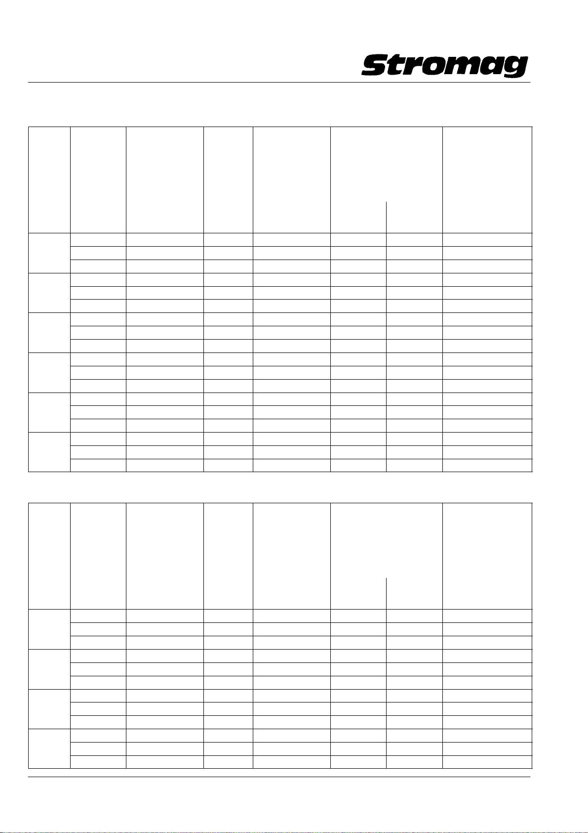
Bühnentechnik / Stage technology
6
4
Getriebe − Nocken − Endschalter Reihe 51 / 51 DZ
Geared Cam Limit Switches Series 51 / 51 DZ
3.2 Getriebedaten / Gear data
Tabelle / Table 4 (Reihe/Series 51)
Getriebe
größe
Gear size
1 6,5 6,2 7,083 0,7 0,063 0,073 0,61
2 29,0 27,0 30,35 3,2 0,27 0,312 2,6
3 125 115,0 130,054 13,9 1,153 1,335 11,2
4 540 495,0 557,284 59,7 4,94 5,723 48,0
5 2288 2100,0 2387,96 256,0 21,18 24,52 205,6
6
Nenn −
Umdrehung
15_ − Nock−
enscheibe
Nominal
revolution
15_ cam disc
4,1 3,8 4,285 0,4 0,038 0,044 0,37
11 10,0 11,56 1,2 0,103 0,118 1,0
17,5 16,0 18,361 1,0 0,163 0,188 1,6
48 44,0 49,538 5,3 0,44 0,508 4,2
75 70,0 78,678 8,4 0,7 0,808 6,8
205 185,0 212,272 22,7 1,883 2,18 18,3
323 300,0 337,135 36,0 2,99 3,462 29,0
880 800,0 909,59 97,5 8,07 9,34 78,3
1384 1280,0 1444,62 155,0 12,81 14,84 124,4
3735 3400,0 3897,58 417,0 34,57 40,03 335,6
5900 5500,0 6190,204 663,7 55,07 63,57 520,1
9800 9000,0 10232,407 1097,0 91,04 105,08 856,6
16000 14500,0 16701,17 1790,7 148,59 171,51 1403,1
Nutzbare
Umdrehungen 40_
Nockenscheibe
Usable revs. 40_
Cam disc
Getriebe
i
Gear ratio
i
Nachlaufumdreh.
der Antriebswelle
nach jeder Seite
Overrun revs. of
drive shaft in each
direction
Umdrehung der Antriebswelle
vom Schaltpunkt bis zur wirk−
samen Zwangstrennung
Rev. of the drive shaft from
switching point up to effec−
tive forced separation
rechtsdreh.
clockwise
linksdreh.
counter
clockwise
Umdrehung der
Antriebswelle für
wirks. Zwangstrennung
Rev. of the drive shaft
from switching point ef−
fective forced separa−
tion with overrun
im Nachlauf
Tabelle / Table 4 a (Reihe/Series 51 DZ)
Getriebe
größe
Gear size
1 110 100 115,68 12,6 1.025 1,187 9,98
2 470 405 495,67 54,3 4,390 5,085 42,77
3 2000 1880 2123,97 323 18,82 21,79 184,1
4
Nenn −
Umdrehung
15_ − Nock−
enscheibe
Nominal
revolution
15_ cam disc
67 62 69,98 7,6 0,62 0,718 6,04
180 165 188,80 20,7 1,673 1,937 16,29
280 265 299,86 32,8 2,656 3,076 25,88
770 715 809,02 88,7 7,168 8,3 69,82
1200 1140 1284,90 140 11,384 13,183 110,9
3300 3000 3466,66 380 30,71 35,57 299,2
5200 4850 5505,87 604 48,78 56,49 475,2
8700 8000 9101,20 998 80,64 93,38 785,4
14200 13200 14854,80 1029 131,61 152,41 1282,0
Nutzbare
Umdrehungen 40_
Nockenscheibe
Usable revs. 40_
Cam disc
Getriebe
i
Gear ratio
i
Nachlaufumdreh.
der Antriebswelle
nach jeder Seite
Overrun revs. of
drive shaft in each
direction
Umdrehung der Antriebswelle
vom Schaltpunkt bis zur wirk−
samen Zwangstrennung
Rev. of the drive shaft from
switching point up to effec−
tive forced separation
rechtsdreh.
clockwise
linksdreh.
counter
clockwise
wirks. Zwangstrennung
Rev. of the drive shaft
from switching point ef−
fective forced separa−
Umdrehung der
Antriebswelle für
im Nachlauf
tion with overrun
Datum / Date 10.2008
2
Page 28
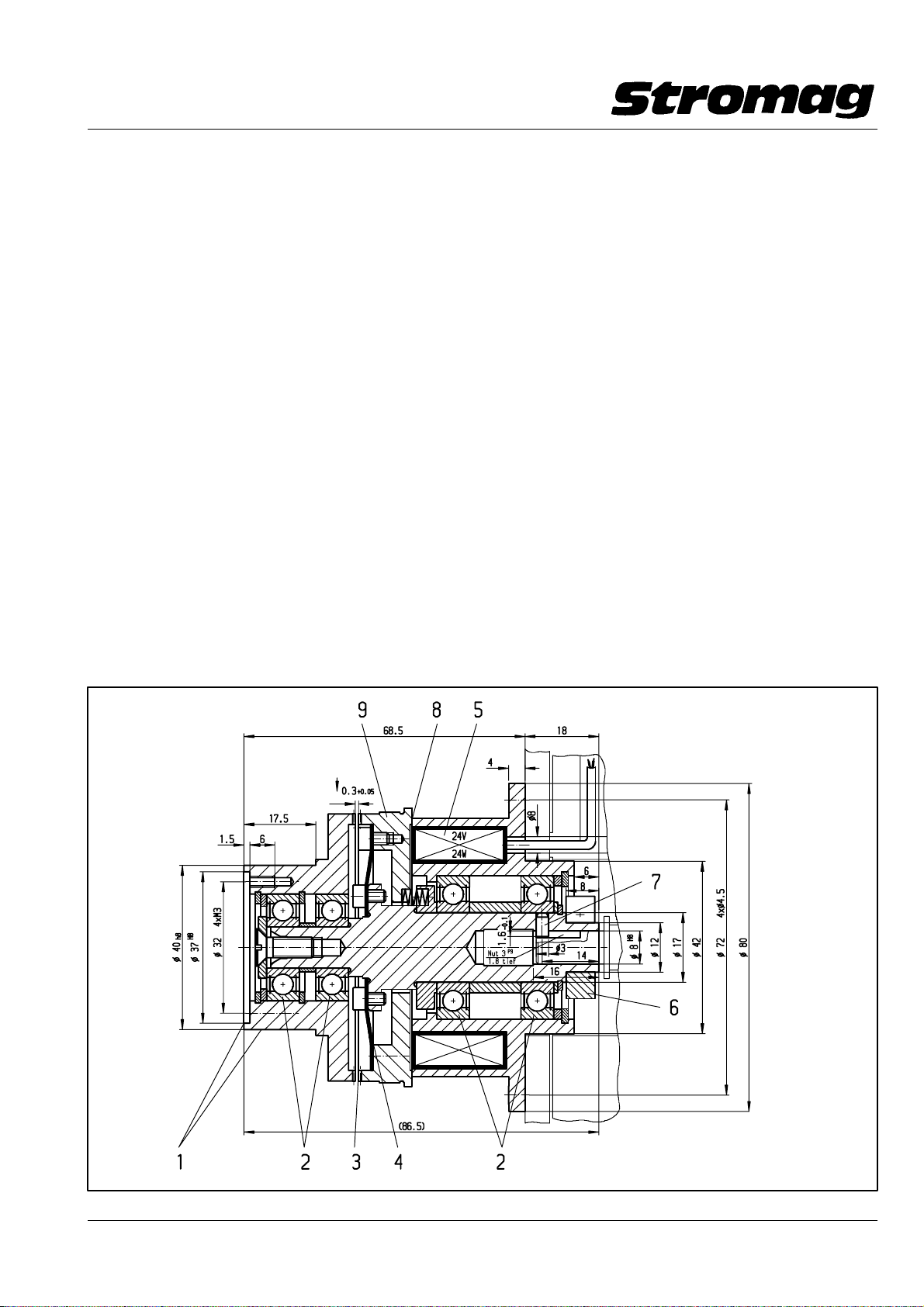
Bühnentechnik / Stage technology
Getriebe − Nocken − Endschalter Reihe 51 / 51 DZ
Geared Cam Limit Switches Series 51 / 51 DZ
3.3 Elektromagnet − Federdruck − Zahnkupplung EZX 0.1
Speziell für die Anforderungen von Punktzugwinden in der
Bühnentechnik wurde die formschlüssige Elektromagnet − Fe−
derdruck − Zahnkupplung EZX 0.1 entwickelt. Sie kann mit al−
len Baureihen der Stromag Steuerstrom − Getriebe − End−
schalter kombiniert werden und erfüllt in der Kombination alle
aus dieser Spezialanwendung bekannten Forderungen in
idealer Weise.
Merkmale (siehe Zeichnung unten)
1 Innen − und Außenzentrierung der Eintriebsnabe für di−
rektes Anflanschen von Controlflex − Kupplungen oder
Ketten − bzw. Zahnriemenrädern.
2 Große Lagerabstände für die Aufnahme großer Radial−
kräfte.
3 Formschlüssige Planverzahnung durch Federdruck ge−
schlossen, elektromagnetisch geöffnet.
4 Spielfreie Drehmomentübertragung durch Doppelmem−
bran.
5 Groß dimensionierte Spule für sicheres Schalten über
großen Luftspalt.
6 Klemmring für spielfreie Drehmomentübertragung auf den
Getriebeschalter.
7 Zusätzliche formschlüssige Wellenverbindung zwischen
Kupplung und Getriebeschalter.
8 Im geöffneten Zustand wirkt die Kupplung als Bremse für
den Getriebeschalter. Eine ungewollte Verstellung ist ver−
hindert.
9 Zusätzliche Zentrierung für das Aufbringen eines Schalt −
ringes zur Schaltzustandsüberwachung der Kupplung
mittels berührungsfreien Schalters (auch in geprüfter
Sicherheit).
3.3 EZX 0.1 Electromagnetic spring − applied toothed
clutch
The EZX 0.1 positive − locking electromagnetic spring − ap −
plied toothed clutch has been developed specially for use
with stage hoisting gear, and can be combined with all Stro−
mag control current geared limit switch series to fully meet all
requirements of this special application.
Features (see drawing below)
1 Internal and external centering of the input hub for direct
flange − mounting of Controlflex couplings or chains and
toothed belt pulleys.
2 Large bearing distances for taking up high radial forces
3 Form − locking rack teeth closed by spring pressure and
opened electromagnetically.
4 Backlash − free torque transmission via double dia−
phragm.
5 Large dimensioned coil for reliable switching via large air
gap.
6 Clamping ring for backlash − free torque transmission to
geared switch.
7 Additional form − locking shaft connection between clutch
and geared switch.
8 In an open condition, the clutch acts as a brake for the
geared switch; accidental adjustment is prevented.
9 Additional centering for the provision of a contact ring for
monitoring the switched condition of the clutch by means
of a contactless switch (also safety approved).
Luftspalt zw. den Zähnen
bei Spule "ein"
Airgap between teeth
with coil "on"
DD140329H
Datum / Date 10.2008
3
Page 29
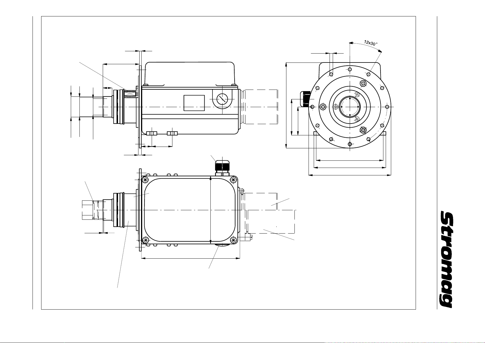
Datum / Date 10.2008
Getr. − Schalter 51 mit El. − Zahnkupplung und Encoder für die Bühnentechnik
Geared switch 51 with el. toothed clutch and encoder for stage technology
Beispielzeichnung (Bauform B3/B5) / Example drawing (Construction B3/B5)
Geared Cam Limit Switches Series 51 / 51 DZ
Bühnentechnik / Stage technology
Getriebe − Nocken − Endschalter Reihe 51 / 51 DZ
4
Spule/Coil 24V
24 Watt
ø 37
ø 40
ø32 4xM3
17.5
70.5
166
70
20 40
6
M20 x 1,5
4
Option CPS − Kupplung/coupling
Elektr.Spulenanschluß
im Schaltergehäuse
Electric coil connection
in the switch housing
132
Option Encoderanbau
Option assembly of encoder
6.4
55
130
140
160
1.5
Elektr.Federdruck − Zahnkupplung EZX0.1
Electromagnetic spring − applied toothed clutch EZX0.1
191
M 20x1,5
Encoderanbau mit Adapterflansch
Assembly of encoder with adapter flange
Anbau von Encodern mit ø36 oder ø50 Flansch direkt am Gehäuse
Direct mounting of encoders to the housing with flange dia. 36 or dia. 50
Bei Encodern mit z.B ø80 Flansch erfolgt der Anbau über ein Adapterstück
Encoders with a flange of e.g. dia. 80 are fitted with an adapter
Bauform/Construction B3/5
DD1_40293H
Page 30
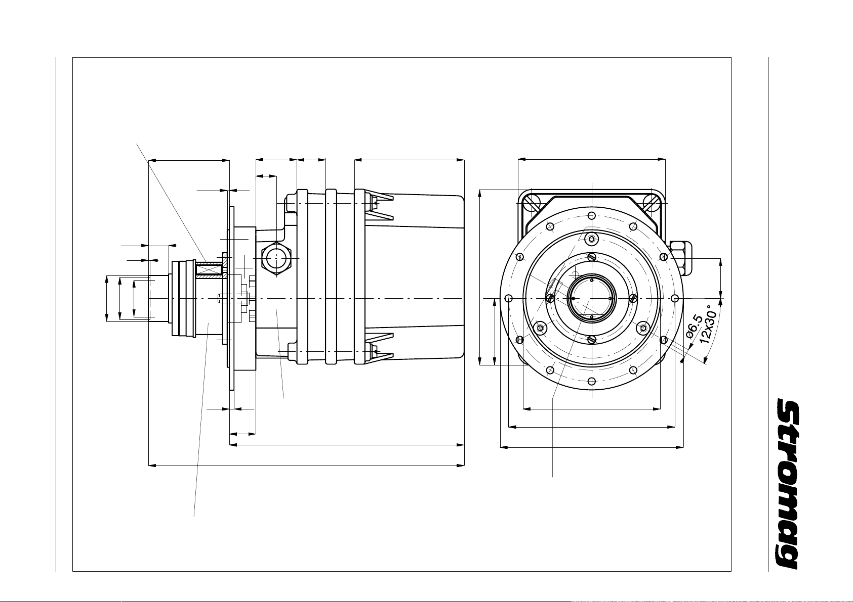
Spule/Coil 24V
24 Watt
Getr. − Schalter 51 mit El. − Zahnkupplung für die Bühnentechnik
Geared switch 51 with el. toothed clutch for stage technology
Bühnentechnik / Stage technology
Getriebe − Nocken − Endschalter Reihe 51 / 51 DZ
Geared Cam Limit Switches Series 51 / 51 DZ
70.5
36
25 96
128
18
2
17.5
1.5
M20x1.5
ø 37
ø 32
4xM3
5
ø 40
4
Elektr.Spulenanschluß im Schaltergehäuse
Electric coil connection in the switch housing
23
205
153
59
120
145
160
35
Datum / Date 10.2008
275
Elektr.Federdruck − Zahnkupplung EZX0.1
Electromagnetic spring − applied toothed clutch EZX0.1
Option CPS − Kupplung/Coupling
Bauform / Construction B5
DD1_40347H
 Loading...