

Page 1

Betriebsanleitung
Getriebe−Endschalter
Reihe 51
Service Instructions
Geared Limit Switches
Series 51
Nr./No. 151−00004
Version: D
Antriebstechnik
von Stromag
Diese Betriebsanleitung soll den Benutzer
dazu befähigen, das Stromag − Produkt si−
cher und funktionsgerecht zu handhaben,
rationell zu nutzen und sachgerecht zu
pflegen, so daß die Gefahr einer Beschädi−
gung oder Fehlbedienung ausgeschlos−
sen wird.
Die Stromag AG ist zertifiziert nach ISO
9001:2000 und nach ISO 14001:1996.
Die Geschäftseinheit Lamellen der Stro−
mag AG ist zertifiziert nach ISO/TS
16949:2002 und nach ISO 14001:1996
This service manual shall enable the user to
operate the Stromag product safely and ef−
fectively, to use it sensibly and to maintain
it properly so as to exclude the possibility of
any damage or incorrect operation.
Stromag AG is certified to ISO 9001:2000
and to ISO 14001:1996.
The business unit "Discs" of Stromag AG is
certified to ISO/TS 16949:2002 and to ISO
14001:1996.
The German wording prevails for sense
and tenor of these instructions.
Page 2

Getriebe − Endschalter / Geared Limit Switches
Reihe / Series 51
Nr./No. 151 − 00004
Inhalt Kapitel
Technische Daten 1
Typschild 1.1
Typenschlüssel 1.2
Technische Daten 1.3
Getriebedaten − Tabelle1
Kontaktdaten − Tabelle 2
Kontaktanschlüsse 1.4
Durchschleifen eines Schutzleiters 1.5
Einsatz und bestimmungsgemäße Verwendung 1.6
Sicherheitshinweise 2
Arbeitssicherheitssymbol 2.1
Achtungshinweis "Achtung!" 2.2
Arbeitssicherheitshinweise 2.3
Elektromagnetische Verträglichkeit 2.4
Transport 3
Verpackung 3.1
Zerlegungsgrad 3.2
Empfindlichkeit 3.3
Zwischenlagerung 3.4
Lieferumfang 3.5
Content Chapter
Technical data 1
Nameplate 1.1
Key to types 1.2
Technical data 1.3
Gear data − Table 1
Contact data − Table 2
Contact connections 1.4
Straight − through grinding
of a protective conductor 1.5
Application and intended use 1.6
Safety guidelines 2
Symbol for safety at work 2.1
Instructions "Caution!" 2.2
Safety instructions for working 2.3
Electromagnetic compatibility 2.4
Transportation 3
Packing 3.1
Pre − mounting condition 3.2
Sensitivity 3.3
In − process stocking 3.4
Delivery extent 3.5
Aufbau, Wirkungsweise,
Konstruktionsmerkmale 4
Einbau des Getriebe − Endschalters 5
Inbetriebnahme 6
Kontakt − Einstellung 6.1
Blockverstellung 6.2
Wirkungsweise 6.2.1
Zusatzausrüstung zur Blockverstellung 6.2.2
Betrieb 7
Betriebsbedingungen 7.1
Schutzarten 7.2
Instandhaltung 8
Sonderausführungen 9
Ausführung mit anderen Nockenwinkeln 9.1
Ausführung mit zusätzlichem Drehwiderstand 9.2
Ausführung mit durchgehender Antriebswelle 9.3
Ausführung mit Heizwiderstand 9.4
Ersatzteilhaltung und Kundendienst 10
Ersatzteilhaltung 10.1
Daten für die Ersatzteilbestellung 10.2
Kundendienstanschrift 10.3
Construction, functioning,
constructional characteristics 4
Assembly of the geared limit switch 5
Commissioning 6
Contact adjustment 6.1
Block adjustment 6.2
Functioning 6.2.1
Accessories for block adjustment 6.2.2
Operation 7
Operation conditions 7.1
Protections 7.2
Maintenance 8
Special executions 9
Execution with various cam angles 9.1
Execution with additional resistors 9.2
Execution with through input shaft 9.3
Execution with heating resistor 9.4
Spare parts stocking and after − sales service 10
Spare parts stocking 10.1
Data for spare parts orders 10.2
Address of the after − sales service 10.3
Entsorgungshinweis 11
Aufgeführte Normen und Vorschriften 12
Datum / Date 10.2008
Hints for waste management 11
Listed standards and regulations 12
1
Page 3
Getriebe − Endschalter / Geared Limit Switches
Reihe / Series 51
Nr./No. 151 − 00004
1 Technische Daten
1.1 Typschild
Folgende Daten befinden sich auf dem Typschild:
Endschalter Reihe 51
Gehäuse − Schutzart IP...
Stromag − Auftrags − Nr. .....
Endschalter Typ s. Kap.1.2
250V
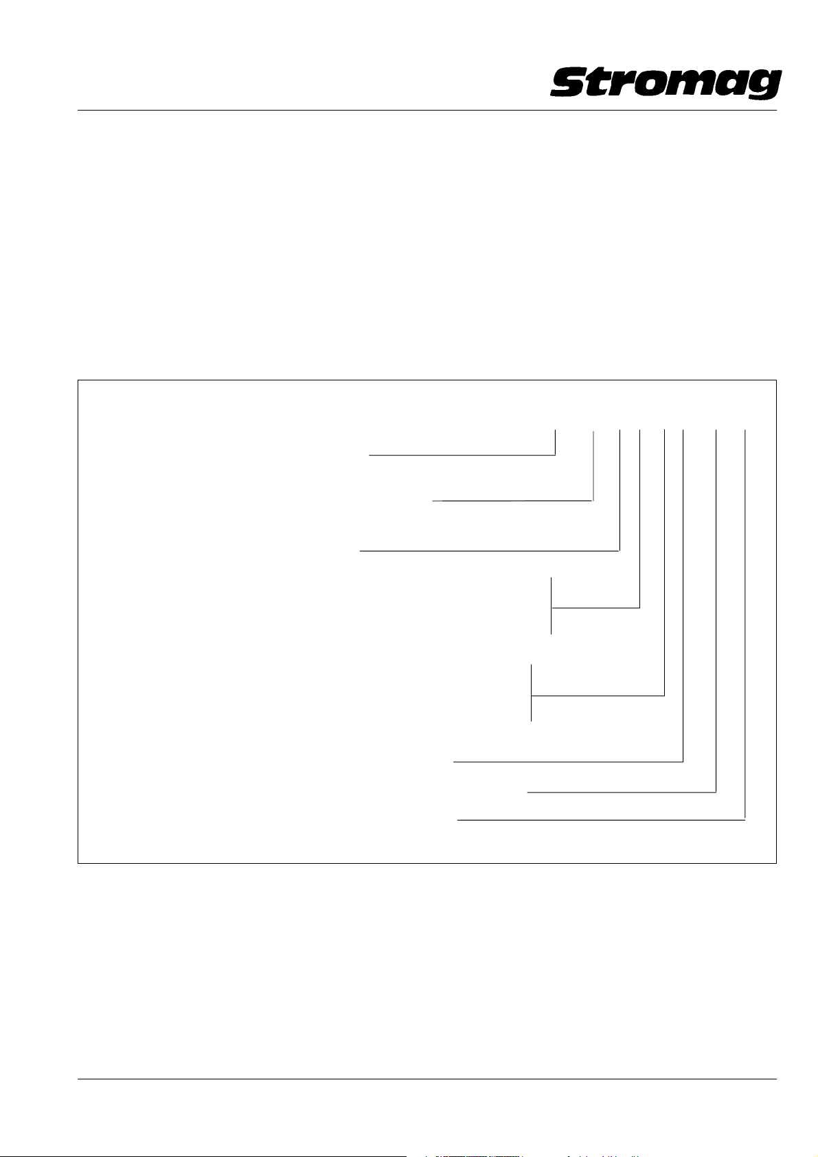
1.2 Typenschlüssel
6A, 24V − 6A
~
Nutzbare Umdrehung / Usable revolutions
(Getriebedaten s. / Gear data see Tab. 1)
N nur bei Getriebe Gr.1 (ohne Blockverstellung)
for gearbox size 1 only (without block adjustment)
B Blockverstellung / Block adjustment
1 Technical data
1.1 Nameplate
The following data is indicated on the nameplate:
Limit switch series 51
Housing protection IP...
Stromag Order − Ref. − No. ....
Limit switch type see chap. 1.2
250V a.c. 6A, 24V d.c. − 6A
1.2 Key to types
NCH
75 B M N K 4 92P A
M Modul − Gehäuse / Modular housing
H Schalter eingebaut im Aluminium − Gehäuse mit hohem Deckel
Switch mounted into aluminium housing with high cover
oder / or
N Schalter eingebaut im Aluminium − Gehäuse mit niedrigem Deckel
Switch mounted into aluminium housing with low cover
oder / or
C Schalter eingebaut im Kunststoff − Gehäuse mit kurzer Haube
Switch mounted into synthetic housing with short cap
oder / or
K Schalter eingebaut im Kunststoff − Gehäuse mit langer Haube
Switch mounted into synthetic housing with long cap
Anzahl der eingebauten Kontakte / No. of contacts fitted
Kontaktbezeichnung (s. Tab. 2) / Type of contacts fitted (see table 2)
Anzeige Blockverstellung / Indication "block adjustment"
1.3 Technische Daten
Die max. zulässige Drehzahl sowie weitere technische
Daten sind für jeden Endschalter − Typ der Getriebe −
bzw. Kontakt − Tabelle zu entnehmen, s. Tabelle 1 und
2.
1.3 Technical data
The max. admissible speed as well as the other techni−
cal data for every limit switch type are indicated in the
gear or contact table resp.: please refer to table 1 and
table 2.
Datum / Date 10.2008
2
Page 4
Getriebe − Endschalter / Geared Limit Switches
Reihe / Series 51
Nr./No. 151 − 00004
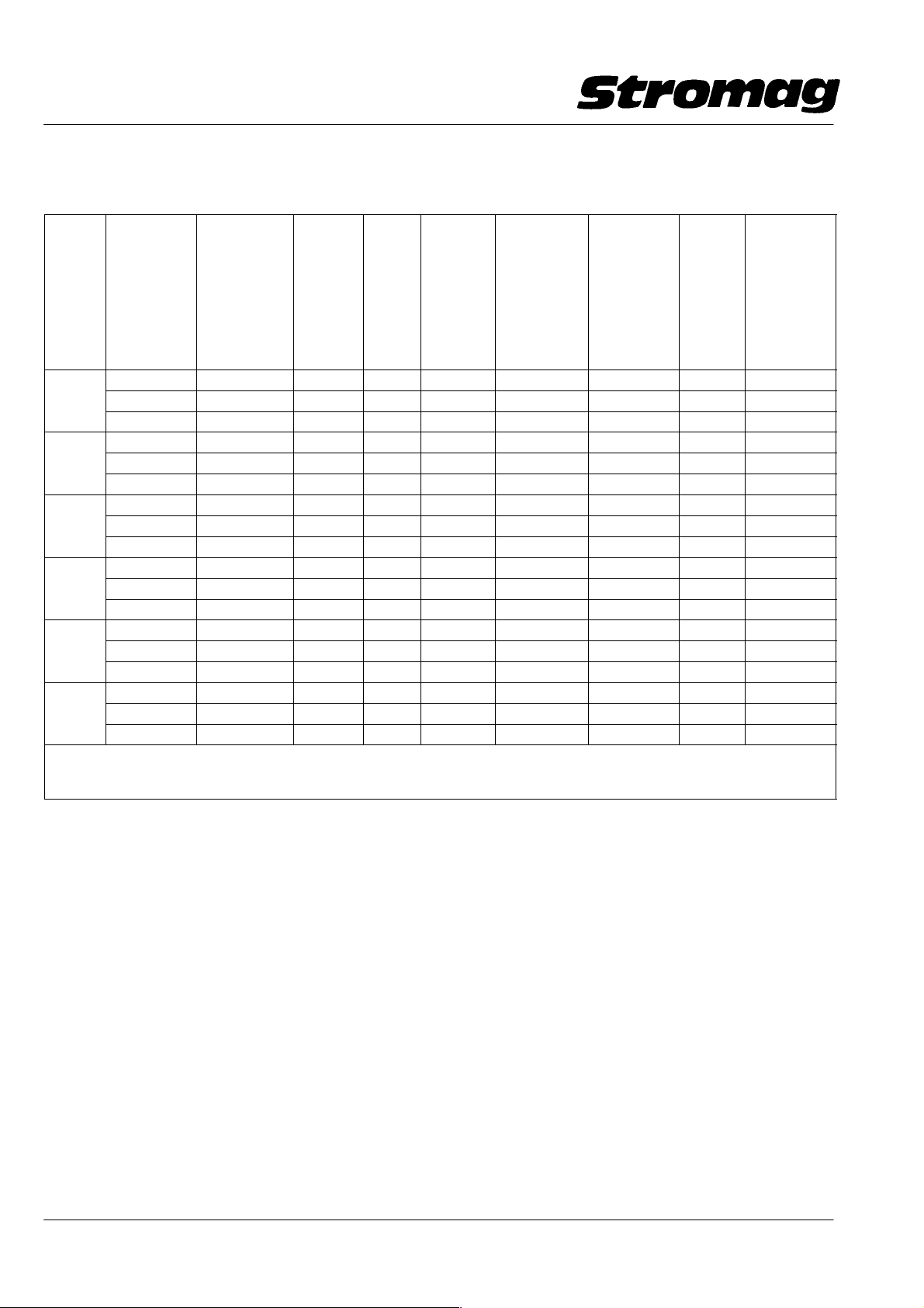
Tabelle / Table 1
Getriebedaten / Gear data
Getrie−
begröße
Gear
size
Nenn − Um−
drehungen
für Nocken−
scheibe 15_
Nominal
revolutions
for cam disc
15_
4,1 4,16 4,285 − 1x4,285 84 0,01 − 0,02 1000 0,67
1 6,5 6,88 7,083 1,653 1x4,285 50,8 0,01 − 0,02 1200 1,1
11 11,23 11,56 2,698 1x4,285 31,14 0,02 − 0,04 1500 1,8
17,5 17,84 18,361 − 2x4,285 19,6 0,03 − 0,06 1800 2,9
2 29,0 29,5 30,35 1,653 2x4,285 11,86 0,05 − 0,1 1800 4,7
48 48,13 49,538 2,698 2x4,285 7,27 0,08 − 0,16 1800 7,7
75 76,45 78,678 − 3x4,285 4,57 0,13 − 0,3 1800 12,2
3 125 126,39 130,054 1,653 3x4,285 2,77 0,21 − 0,42 1800 20,2
205 206,26 212,272 2,698 3x4,285 1,69 0,35 − 0,68 1800 33
323 327,6 337,135 − 4x4,285 1,06 0,6 − 1,17 1800 52
4 540 541,5 557,284 1,653 4x4,285 0,65 0,92 − 1,8 1800 87
880 883,8 909,59 2,698 4x4,285 0,4 1,5 − 2,9 1800 141
1384 1403,7 1444,62 − 5x4,285 0,25 2,4 − 4,7 1800 224
5 2288 2320,2 2387,96 1,653 5x4,285 0,15 3,9 − 7,7 1800 371
3735 3787,1 3897,58 2,698 5x4,285 0,09 6,5 − 12,7 1800 606
5900 6014,77 6190,204 − 6x4,285 0,06 10,3 − 20,1 1800
6 9800 9942,42 10232,407 1,653 6x4,285 0,04 17,0 − 33,3 1800
16000 16227,86 16701,17 2,698 6x4,285 0,02 27,8 − 54,2 1800
Nutzbare
Umdrehungen
theo. bei Nok−
kenscheiben
15_
Usable revs.
theor. at cam
discs 15_
Ge −
triebe i
Gear −
ratio i
Vorsatz−
stufe
Input/
output
stage
Anzahl
i
ges.
Planeten −
stufen
No. of
planetary
stages i
1 Umdr. der
Antriebswelle
= Grad an der
Nocken−
scheibe
1 rev. of the
drive shaft −
corresp. to an
ang. motion of
cam disc =_
Rückschalt −
Umdr. an der
Antriebswelle
für Schnapp−
schalter
Reset rev. at
driving shaft
for snap ac−
tion
max.
Antriebs−
drehzahl
max.
drive
speed
−1
min
1 Umdrehung der Verstellschnecke entspricht 2.464° an der Nockenscheibe
1 rev. of the adjusting worm corresponds to 2.464° at the cam disc
1)
Nur als Öffner − Kontakt zu verwenden / Only use as normaly closed contact
min. Antriebs−
drehzahl (nur
bei Wechsler)
min. drive
shaft (only for
change − over
contact)
−1
min
1)
1)
1)
Datum / Date 10.2008
3
Page 5
Getriebe − Endschalter / Geared Limit Switches
yp
gp
IEC947−5−1
Wechsler
Schnapp
S
ja/y
ja/yes
1.5
230
10
nal
d
Sil
schaltung
Reihe / Series 51
Nr./No. 151 − 00004
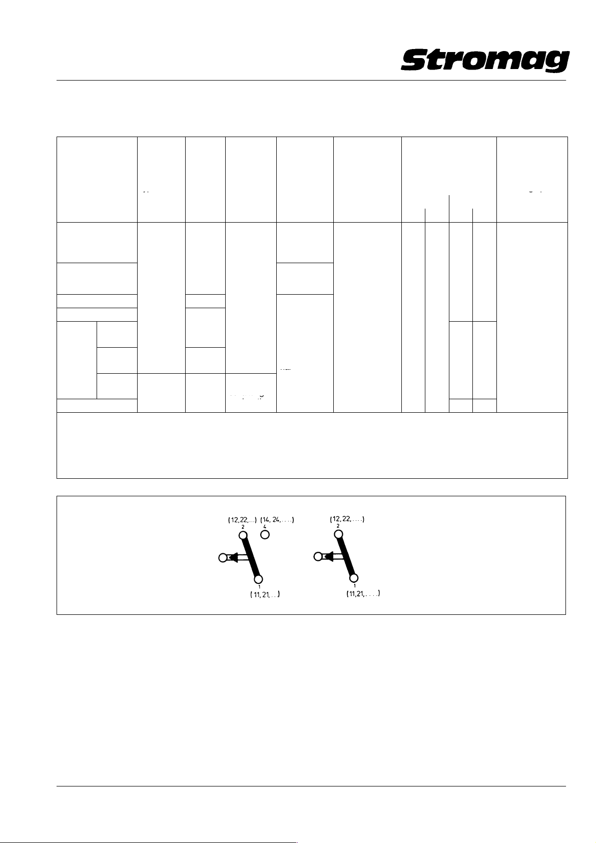
Tabelle 2 / Table 2
Kontaktdaten / Contact Data
Kontakt −
bezeichnung
Contact designation
1)
99
1)
99P
1) 3)
99G
99L
Nicht für
Neukon−
struktion
Not for
new
con−
struction
1)
Therm. Dauerstrom Ith = 10A; Bemessungsisolationsspannung U
Thermal permanent current Ith = 10A; Reference insulation voltage U
2)
Therm. Dauerstrom Ith = 6A; Bemessungsisolationsspannung U
Thermal permanent current Ith = 6A; Reference insulation voltage U
3)
Kontakte 99G und 97 für SPS − Anwendungen (Goldkontakte) / Contacts 99G and 97 for PLC applications (gold contacts)
4)
Bei Schraubenanschluss zulässiger Leiterquerschnitt: 0,5 − 1,5mm2/For screw terminals admissible cable cross section AWG 22 − 16
99T
92
97
96
4)
2)
2)3)
2)
Kontaktart
Contact
type
Wechsler
Change −
over cont.
Öffner
Normally
close
contact
Kontakt−
werkstoff
Contact
material
Silber
Silver
Gold
Silber
Silver
Gold
Silber
ver
Schalt −
system
Switch
actuation
Schnapp −
schaltung
nap action
Tast −
schaltung
push action
Kontaktan−
schlußart
Type of
contact
connection EN60947T5 − 1
Schrauban−
schluß
Screw termi−
nal
Flachstecker
6,3
Flat plug 6,3
Schrauban−
schluß
Screw termi−
nal
i
= 250V bei Verschmutzungsgrad 3
i
Zwangstrennung
nach
Positive opening
to
IEC947 −5−1
es 1.5 230 10
= 250V bei Verschmutzungsgrad 3
= 250V at pollution degree 3
i
= 250V at pollution degree 3
i
Elektrische Daten
Electrical data
nach/to EN 60947 − 5 − 1
AC − 15 DC − 13
I[A] U[V] I[A] U[V]
0,5 60
− −
0,5 60
mechanische
Lebensdauer
in Mio
Schaltungen
Mech. life in mio.
switching opera −
tions
Wechsler
Change over contact
92
97
99G
99P
1.4 Kontaktanschlüsse
Die Kontaktanschlüsse können, je nach Art, über
Schraubenanschlüsse für Leiterquerschnitt
0,75 − 1,5 mm2/AWG 18 − 16 oder über Flachstecker
6,3x0,8 mm2 oder über Leiterplatte mit Käfig − Zugfe−
derklemmen für Querschnitt 0,14 − 2,5mm2/AWG
26 − 14 erfolgen. Bei Verwendung von Schrauban−
schlüssen beträgt das zulässige Anzugsmoment der
Schrauben max. 1 Nm.
4
Öffner
Normally closed contact
96
99T
1.4 Contact connections
The contacts can either be connected through screw
terminals for a cable cross section of 0,75 to 1.5 mm
/AWG 18 − 16 or through flat plugs 6.3x0.8 mm2 or
through a printed card with cage tension spring termi−
nals for a cross section of 0.14 to 2.5 mm2.
When using screw terminals the admissible tightening
torque of the screws is max. 1 Nm.
Datum / Date 10.2008
2
Page 6
Getriebe − Endschalter / Geared Limit Switches
Reihe / Series 51
Nr./No. 151 − 00004
Anschluß der Käfig − Zugfederklemmen: Durch Einfüh−
rung einer maximal 2,5 mm breiten Schraubendreher−
klinge in den oberhalb der Leitungs − Einführungsöff−
nung befindlichen Schlitz, wird die Leitungsklemmfeder
zur Einführung des abisolierten Leitungsendes geöff−
net. Das Leitungsende soll 6 mm abisoliert sein. Es kön−
nen eindrähtige bis feindrähtige Leitungen, wahlweise
mit oder ohne Adernendhülse, angeschlossen werden.
Der Kontakt Nr. 1 befindet sich immer an der Antriebs−
wellenseite.
Die Käfig − Zugfederklemme auf oder unter der Leiter−
platte ist immer für Wechsler − Kontakte ausgelegt (3
Anschlüsse je Kontakt). Bei Verwendung von Öffner−
kontakten (2 Anschlüsse) ist die Schließerklemme nicht
belegt.
Kontakte mit Schraubanschlüssen werden grundsätz−
lich mit Berührungsschutz geliefert. Bei diesen Kontak−
ten ist sicherzustellen, daß vor der Inbetriebnahme alle
Schrauben der Schraubanschlüsse, ob mit Kabel be−
legt oder nicht, fest angezogen sind.
Für Kontakte mit Flachstecker − Anschluß und bei
Spannungen über 25V/AC bzw. 60V/DC sind kunden−
seitig vollisolierte Flachsteckhülsen als Berührungs−
schutz zu verwenden.
Wird bei Wechsler − Kontakten nur die Öffnerfunktion
benötigt, ist auch der nicht benötigte Schließeran−
schluß mit einer vollisolierten Flachsteckhülse als Be−
rührungsschutz zu versehen.
Connection of the cage tension spring terminals: By in−
serting a screw driver knife − max. width 2.5 mm − into
the slot located above the cable inlet hole, the cable ter−
minal spring is opened for insertion of the bared cable
end. Cable end 6 mm bared. Optionally unifilar up to
fine − strand cables with or without end sleeves for
strands can be connected. The contact No. 1 is always
at the driving shaft side.
The cage tension spring terminal on or below the prin−
ted card is always designed for the change − over con−
tacts (3 connections per contact). When using normally
closed contacts (2 connections), the normally open ter−
minal is not connected.
Contacts with screw terminals are generally supplied
with protection against accidental touch. For these con−
tacts ensure that all terminal screws − used and un −
used − are fully tightened before putting the switch into
service.
For contacts with flat plug connection and with voltages
exceeding 25 volts/AC or 60 volts/DC resp., the custo−
mer has to use fully − insulated receptacles for tabs as
protection against accidental touch.
If with change − over contacts the function of the nor−
mally closed contact is required only, the not − required
normally open contact has also to be provided with a
fully − insulated receptacle for tabs as protection
against accidental touch.
1.5 Durchschleifen eines Schutzleiters bei Ge −
häuseausführungen IP 65 und IP 66
Ein Schutzleiter bis maximal 2,5 mm2 kann durch eine
Brückenverschraubung, am hinteren Kontaktträger be−
festigt, verbunden und durchgeschleift werden.
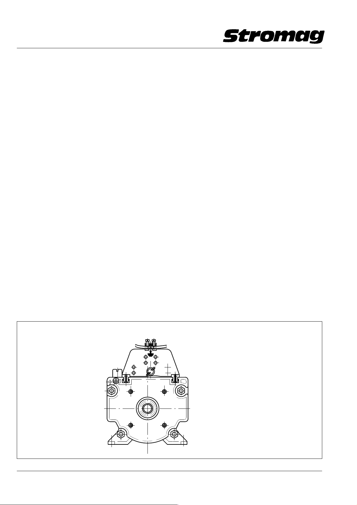
Klemmung mit oder ohne Aderendhülse / Terminal with or without end sleeve for strands
1
2
4
Stromag
1.5 Straight − through grinding of a protective con−
ductor with housing execution IP 65 and IP 66
A protective conductor up to max. 2.5 mm2 can be con−
nected by a bridge gland, fastened to the rear contact
carrier, and can be ground straight − through.
1
2
4
Bild / Fig. 1
Datum / Date 10.2008
DD1_40644V
5
Page 7
Getriebe − Endschalter / Geared Limit Switches
Reihe / Series 51
Nr./No. 151 − 00004
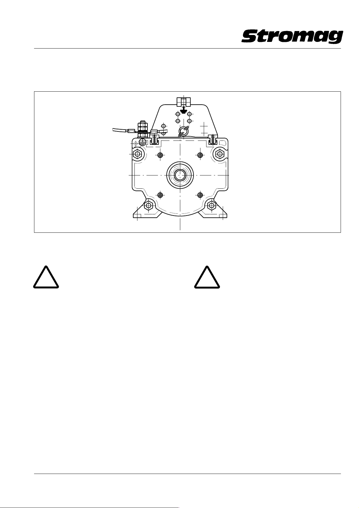
Alternativ dazu kann eine Verbindung des Schutzleiters
mit Hilfe von Kabelschuhen und einer im hinteren Mo−
dulteil eingeschraubten M4 − Schraube erfolgen.
1
M4
Bild / Fig. 1a
2
4
Optionally the connection of the protective conductor
can be made by means of cable shoes and M4 − screw,
which is screwed into the rear module part.
1
2
Stromag
4
DD1_40645V
1.6 Einsatzbereich und bestimmungsgemäße Ver−
wendung
!
Der Getriebe − Endschalter ist entspre−
chend seiner Schutzart gem. Kap. 7.2 und Schalt −
leistungen gem. Tab. 2 einzusetzen.
Die Betriebsbedingungen gem. Kap. 7.1 sind zu be−
achten.
Ferner sind die vom Hersteller vorgeschriebenen
Einbau − und Instandhaltungsbedingungen einzu−
halten.
Bei Einbau des Endschalters mit Schutzart IP 00
oder IP 20 zusammen mit Hauptstromschützen, be−
sonders in kleinen Schaltkästen, kann sich das im
Schaltfunken entstehende Ozon im Schaltkasten
anreichern.
Ozon kann unter bestimmten Bedingungen die
Kunststoffteile angreifen.
Bei einer solchen Anordnung bitten wir um Rück−
sprache mit unserem technischen Kundendienst,
Anschrift siehe Kap. 10.3.
Die Nichtbeachtung der o.g. Bedingungen oder je−
der darüber hinausgehende Gebrauch gilt als nicht
bestimmungsgemäß.
Für hieraus resultierende Schäden haftet der Her−
steller nicht; das Risiko hierfür trägt allein der Benut−
zer.
1.6 Application range and intended use
!
The geared limit switch has to be used in
compliance with its type of protection as per chapter
7.2 and its switching capacity as per table 2.
The service conditions as per chpater 7.1 have to be
adhered to.
The instructions for assembly and maintenance, gi−
ven by the manufacturer, must be adhered to.
When fitting limit switches with protection IP 00 or IP
20 in combination with main current contactors, par−
ticularly in small switch boxes, the ozone generated
in the switching spark can enrich in the switch box.
Under certain conditions, ozone can affect the parts
of synthetic material.
In case of such an arrangement, please consult our
technical after − sales service (the address is given
in chapter 10.3).
Failure to observe such instructions or any usage
over and above the specified applications will be
deemed to be improper use.
The manufacturer will not be liable for any damage
caused by such actions and the user will bear sole
responsibility in such cases.
Datum / Date 10.2008
6
Page 8

Getriebe − Endschalter / Geared Limit Switches
Reihe / Series 51
Nr./No. 151 − 00004
2 Sicherheitsshinweise
2.1 Arbeitssicherheits − Symbol
!
Dieses Symbol finden Sie bei allen Arbeitssi−
cherheits − Hinweisen in dieser Betriebsanleitung (BA),
bei denen Gefahr für Leib und Leben von Personen be−
steht. Beachten Sie diese Hinweise und verhalten Sie
sich in diesen Fällen besonders vorsichtig. Geben Sie
alle Arbeitssicherheits − Hinweise auch an andere Be−
nutzer weiter.
2.2 Achtungshinweis
Dieses "Achtung!" steht an den Stellen in dieser BA, die
besonders zu beachten sind, damit die Richtlinien, Vor−
schriften, Hinweise und der richtige Ablauf der Arbeiten
eingehalten werden, sowie eine Beschädigung und
Zerstörung des Endschalters verhindert wird.
2.3 Arbeitssicherheitshinweise
Folgende Arbeitssicherheitshinweise sind besonders
zu beachten:
Der Endschalter ist nach dem Stand der Technik gebaut
und ist betriebssicher. Von diesem Gerät können aber
Gefahren ausgehen, wenn es von ungeübtem Personal
unsachgemäß oder zu nicht bestimmungsgemäßem
Gebrauch eingesetzt wird.
Jede Person, die im Betrieb des Anwenders mit der
Montage, De − und Remontage, Inbetriebnahme, Be−
dienung, und Instandhaltung des Endschalters befaßt
ist, muß die komplette BA und besonders die Endschal−
ter − Sicherheitshinweise gelesen und verstanden ha−
ben.
Für Schäden und Betriebsstörungen, die sich aus der
Nichtbeachtung der BA ergeben, übernehmen wir kei−
ne Haftung.
Es ist jede Arbeitsweise zu unterlassen, welche die Si−
cherheit des Endschalters beeinträchtigt.
Der Bediener ist verpflichtet, eintretende Veränderun−
gen an dem Endschalter, welche die Sicherheit beein−
trächtigen, sofort zu melden.
Der Anwender ist verpflichtet, den Endschalter immer
nur in einwandfreiem Zustand zu betreiben.
Eigenmächtige Umbauten und Veränderungen, welche
die Sicherheit beeinträchtigen, sind ebenso wie der Ein−
satz fremder Zubehörteile nicht gestattet.
Nach entsprechender Elektro − Montage oder − In−
standsetzung sind die eingesetzten Schutzmaßnah−
men zu testen (z.B. Erdungwiderstand).
Achtung!
2 Safety Guide Lines
2.1 Symbol for safety at work
!
This symbol denotes all the safety instruc−
tions in this manual which deal with danger to life and
limb of personnel. These instructions must be adhered
to and particular caution exercised in these cases. All
users must be familiarised with the safety instructions.
2.2 Instructions
The term "caution" denotes those sections in this ma−
nual which require special attention, in order that the
guidelines, recommendations and correct procedures
are complied with to prevent damaging or destroying
the limit switch.
2.3 Safety instructions for working
The following recommendations are of particular impor−
tance:
The limit switch has been manufactured to the highest
up to date standard and is operationally safe. Howe−
ver, the product can become a risk to safety when used
improperly by untrained personnel or for an application
it is not designed for.
Every person involved in assembling, disassembling,
commissioning, operating and maintaining (inspecting,
servicing and repairing) the limit switch must be autho−
rised, adequately trained and instructed. Each such
person must have read and understood this instruction
manual, especially in respect to the safety instructions.
We do not accept liability for damage or malfunctioning,
resulting from non − adherence to this manual.
Any work process involving the limit switch which im−
pairs safety is to be avoided.
The user is obliged to inform the supplier imme − diately
of any change occuring to the limit switch which adver−
sely affects safety. (Address see chapter 8.3).
The user is obliged to only operate the limit switch when
it is functioning correctly.
Unauthorised changes and modifications which impair
safety, as well as the use of non − authentic components
is not permitted.
After electrical assembly or repair a full electrical safety
check should be made (e.g. earth resistance).
Caution!
Achtung!
die örtlichen Sicherheits − und Unfallverhütungs−
vorschriften. Der Anwender hat für die Einhaltung
dieser Vorschriften zu sorgen.
Datum / Date 10.2008
Für den Betrieb gelten in jedem Fall
Caution!
dent prevention regulations are also applicable, the
user must ensure that these are complied with.
7
In every case the local safety and acci−
Page 9
Getriebe − Endschalter / Geared Limit Switches
Reihe / Series 51
Nr./No. 151 − 00004
Gegenüber Darstellungen und Angaben dieser BA sind
technische Änderungen, die zur Verbesserung der
Endschalter notwendig werden, vorbehalten.
Wir empfehlen, diese Anleitung als Bestandteil in die BA
des Anwenders (Maschinenhersteller) aufzunehmen.
2.4 Elektromagnetische Verträglichkeit
Die Einhaltung der Richtlinie über die elektromagneti−
sche Verträglichkeit 89/336/EWG ist unter Beachtung
der Druckschrift "EMV − Hinweise für Betrieb und Instal−
lation von Elektromagnet − Kupplungen und − Bremsen
und Endschaltern" Nr. 900 − 00001 vom Benutzer (Anla−
gen − oder Maschinenhersteller) sicherzustellen.
Druckschrift auf Anforderung.
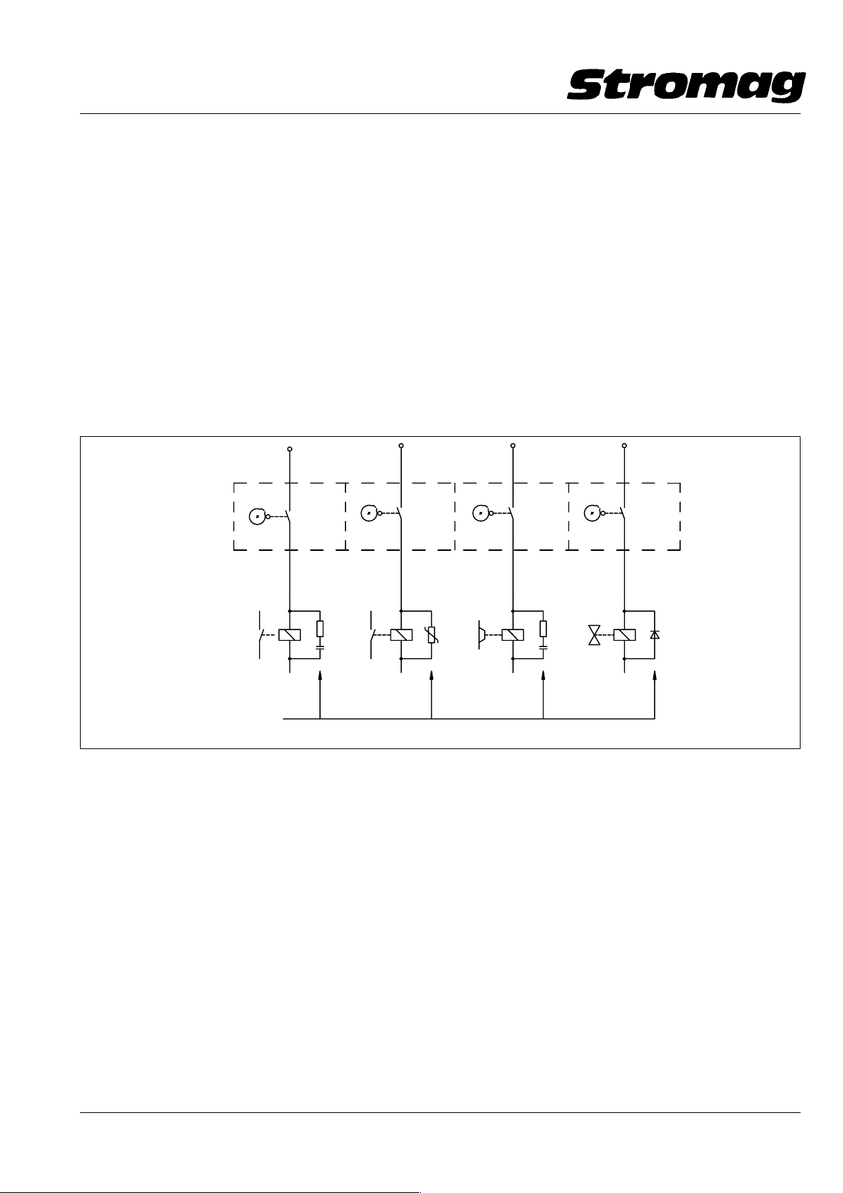
Störaussendungen sind nach Möglichkeit an der Stör−
quelle zu beseitigen.
Dazu nachfolgend prinzipielle Schutzbeschaltungen je
nach Art der vom Kontakt geschalteten Last.
Kontakt im Endschalter
Contact in the limit switch
We reserve the right to make modifications of a techni−
cal nature to this manual if required for limit switch de −
velopment.
We recommend that these instructions are incorpora−
ted into the service manual of the user.
2.4 Electromagnetic compatibility
The user (system or machine manufacturer) has to as−
sure that the regulation for electromag − netic compati−
bility 89/336/EEC is adhered to, taking also into account
the leaflet "EMC notes for operation and mounting of
electromagnetic clutches and brakes and limit swit−
ches", No. 900 − 00001.
The leaflet is forwarded on request.
As far as possible, interferences have to be eliminated
at the source of interference.
See below principle protective wiring in relation to the
type of load operated by the contact.
geschaltete Last
switched load
Schutzbeschaltung
Protective wiring
Schütze
Contactors
3 Transport
3.1 Verpackung
Mitentscheidend für die Verpackunggsart ist der Trans−
portweg. Die auf der Verpackung angebrachten Bildzei−
chen sind zu beachten.
3.2 Zerlegungsgrad
Der Getriebe − Endschalter wird komplett montiert ge−
liefert.
3.3 Empfindlichkeit
Beim Transport des Endschalters ist besonders vor−
sichtig zu verfahren, um Schäden durch Gewalteinwir−
kung oder unvorsichtiges Be − und Entladen zu verhin−
dern. Je nach Art und Dauer des Transportes sind
entsprechende Transportsicherungen vorgesehen.
Während des Transportes sind Kondenswasserbildung
auf Grund großer Tremperaturschwankungen sowie
Stöße zu vermeiden.
Relaisspulen
Relay coils
Kupplungen/Bremsen
Clutches/brakes
Ventile
Valves
3 Transportation
3.1 Packing
The type of packing depends on the transportation
route and the delivery extent. The symbols marked on
the packing must be adhered to.
3.2 Pre − mounting condition
The geared limit switch is supplied completely moun−
ted.
3.3 Sensitivity
Be particularly careful on transportation of the limit
switch in order to avoid damage due to external force
or careless loading and unloading. In relation to trans−
portation type and time, corresponding transportation
protection devices have to be provided. During trans−
portation avoid shocks as well as the generation of con−
densation water due to temperature fluctuations.
DD1_40268V
Datum / Date 10.2008
8
Page 10
Getriebe − Endschalter / Geared Limit Switches
Reihe / Series 51
Nr./No. 151 − 00004
3.4 Zwischenlagerung
Bei der Zwischenlagerung ist wie beim Transport Kon−
denswasserbildung durch große Temperaturschwan −
kungen zu vermeiden. Eine Staubbildung sollte eben−
falls vermieden werden. Endschalter der Schutzart IP
00 und IP 20 sollten nach Möglichkeit in ihren Transport−
verpackungen zwischengelagert werden.
3.5 Lieferumfang
Der Inhalt der Verpackung ist auf der Packliste aufge−
führt, deren Vollständigkeit beim Empfang zu überprü−
fen ist. Eventuelle Transportschäden und /oder feh−
lende Teile sind sofort zu melden.
4 Aufbau, Wirkungsweise, Konstruktionsmerk−
male
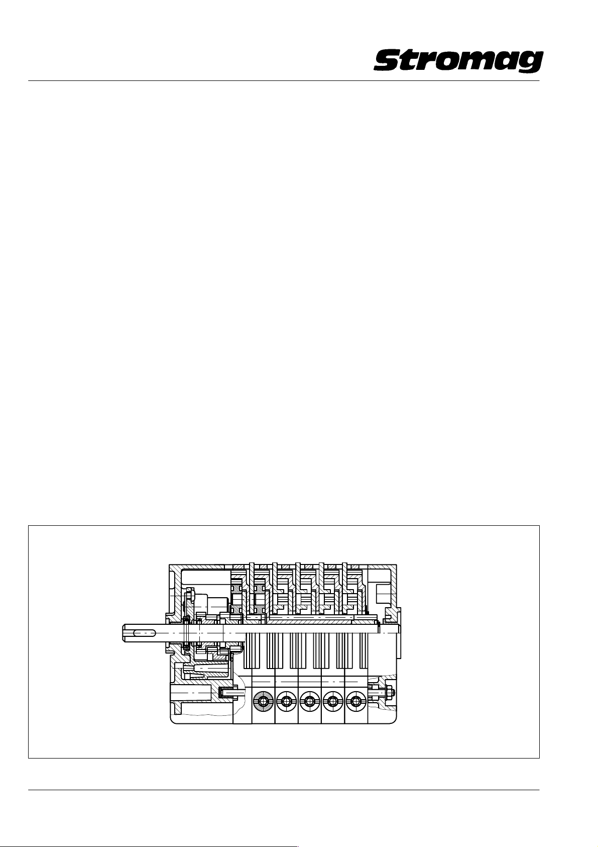
(s. Bild 2)
Die eingebauten wartungsfreien Planetengetriebe mit
oder ohne Stirnrad − Voruntersetzungsstufe sind aus
thermoplastischem Kunststoff hergestellt.
Die Schaltstufen sind durch die verwendete Modultech−
nik mit gleichen Teilen wie die Planetengetriebe ausge−
rüstet. Hinzu kommt eine Nockenscheibe und eine Ver−
stellschnecke.
Die Planeten − und Schaltstufen sowie die Stirnradvor−
untersetzungsstufe (bei bestimmten Untersetzungen
nicht erforderlich, s. Getriebedaten Kap. 1.3 Tabelle 1)
sind in einem glasfaserverstärkten Kunststoff − Modul −
Gehäuse eingebaut.
Die Kontakte (s. Kap. 1.3, Tabelle 2) werden durch die
Nockenscheiben der Schaltstufen betätigt.
3.4 In − process stocking
In case of in − process stocking as well as during trans−
portation avoid the generation of condensation water
by strong temperature fluctuations. Also avoid the ge−
neration of dust. Limit switches of protection IP 00 and
IP 20 shall be stocked in their transportation package,
if possible.
3.5 Delivery extent
On receipt check the consignment for completeness.
Possible damage during transportation and/or missing
parts must be advised immediately and in writing.
4 Construction, functioning, constructional
characteristics
The fitted maintenance − free planetary gears with or
without spur gear pre − step down are made of thermo−
plastic plastics.
Because of the applied modular technology the swit−
ching steps are equipped with the same parts as the
planetary gears. A cam disc and an adjusting worm are
added.
The planetary and switching steps as well as the spur
gear pre − step down (not necessary for certain reduc−
tions, see gear data in chap. 1.3, table 1) are mounted
into a glass − fiber reinforced modular housing of syn−
thetic material.
The contacts (see chap. 1.3, table 2) are actuated by
the cam discs of the switching steps.
(see Fig. 2)
Bild / Fig. 2
Datum / Date 10.2008
DD1 404 76V
9
Page 11

Getriebe − Endschalter / Geared Limit Switches
Reihe / Series 51
Nr./No. 151 − 00004
5 Einbau des Getriebe − Endschalters
Achtung!
siertem, ausgebildetem und eingewiesenem Perso−
nal bedient, gewartet und instandgesetzt werden.
Dieses Personal muß die komplette BA gelesen, ver−
standen und eine spezielle Unterweisung über auf−
tretende Gefahren erhalten haben.
Die Einbaulage des Getriebe − Endschalters mit oder
ohne Schutzgehäuse ist beliebig. Der Antrieb sollte
nach Möglichkeit über ein elastisches Bindeglied, z.B.
einer elastischen Membrankupplung, erfolgen. Bei An−
trieb über Kettentrieb, Zahnriemen usw. darf die zuläs −
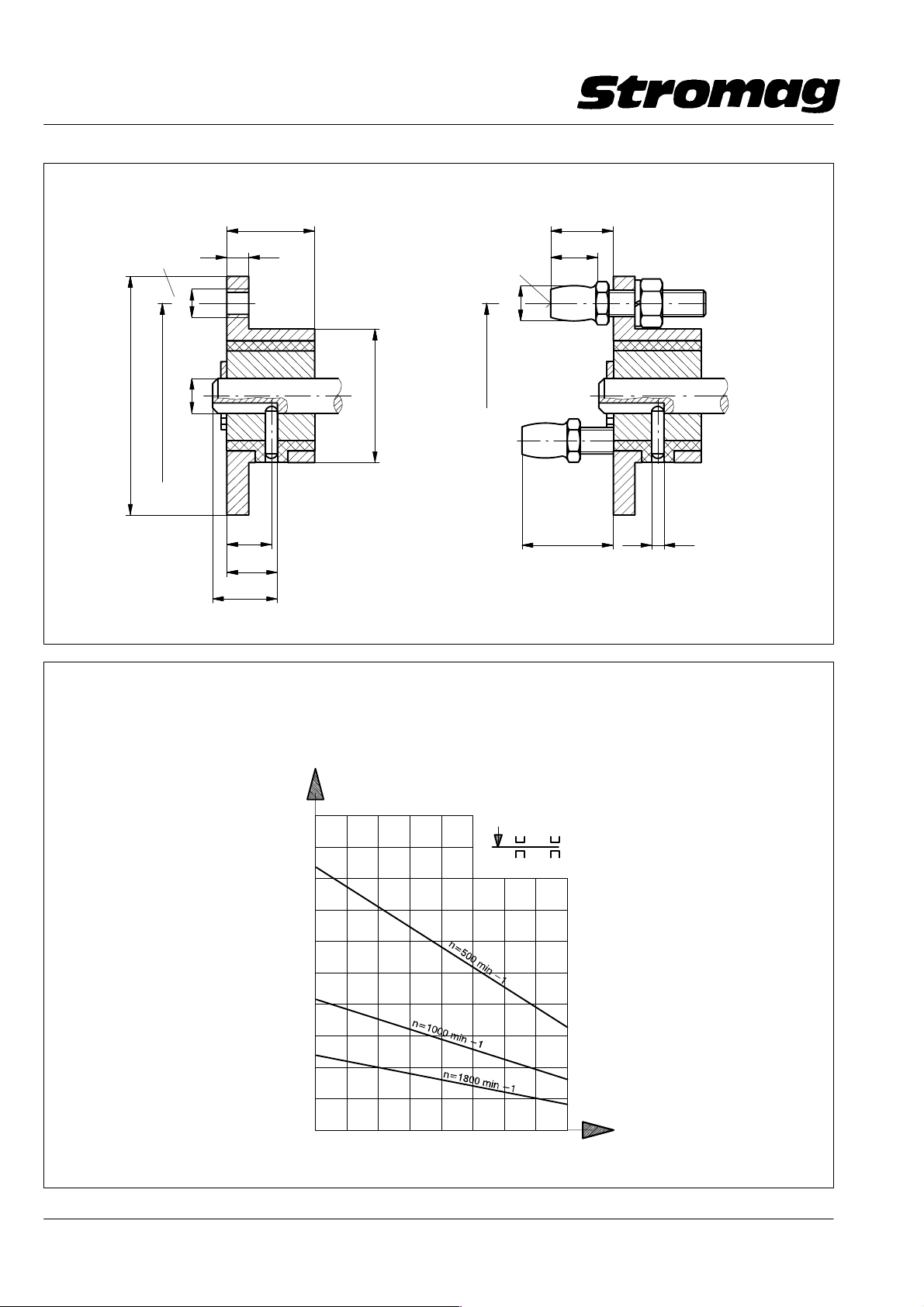
sige Querkraft F
3). Bei Schutzartgehäusen, außer C/K − Gehäusen, ist
zusätzlich zum Gleitlager ein Rillenkugellager einge−
baut. Bei Verwendung dieser Gehäuse kann der zuläs−
sige Kurvenwert verdoppelt werden.
Stoßartige Axialkräfte auf die Antriebswelle müssen ver−
mieden werden.
Der ideale Antrieb erfolgt über eine drehsteife elasti−
sche Kupplung mit geringen axialen und radialen Rück−
stellkräften. Hierbei werden Fluchtfehler und Achsver−
satz ausgeglichen, z.B. Flansche Typ F oder Typ F+M,
s. Bild 2a (nicht für C/K − Gehäuse).
Nach der Schaltpunkteinstellung bei der Inbetriebnah−
me soll der Endschalter sofort wieder mit der Haube
verschlossen werden, damit kein eindringender Staub
oder Wasser die Abschaltsicherheit beeinträchtigen
kann.
Ebenso werden dadurch Unfälle durch die Berührung
spannungsführender Teile verhindert.
Beim Aufsetzen der Haube ist auf vollzähliges und
gleichmäßiges Anziehen der Schrauben zu achten, da−
mit ein Verkanten der Haube und eine schlechte An−
pressung der Dichtung vermieden wird.
Die verwendeten Kabel − Verschraubungen entspre−
chen der Schutzart IP 68. Bei der Kabelmontage ist be−
sonders darauf zu achten, daß die Klemm − Mutter nach
der Einführung des Kabels sorgfältig angezogen wird.
Das Anzugsmoment soll je nach Kabelart zwischen 2
und 3 Nm liegen.
Da sich der Kunststoffmantel bei einigen Kabeln an der
Klemmstelle in der Kabel − Verschraubung durch die
Einschnürung bleibend verformt, ist es ratsam die
Klemm − Mutter nach 3 − 4 Tagen um eine halbe Umdre−
hung nachzuziehen.
Die Kabelführung zum Endschalter soll so ausgeführt
sein, daß das Kabel kein Wasser an die Kabel − Ver−
schraubung leiten kann.
Der Endschalter darf nur von autori−
nicht überschritten werden (s. Bild
max
5 Assembly of the geared limit switch
Caution!
maintaining and repairing the limit switch must be
authorized, adequately trained and instructed.
Each such person must have read and understood
this instruction manual and must have been instruc−
ted in particular in relation to possible danger.
Mounting position of the geared limit switch with or wi−
thout protective housing as required. The drive shall be
transmitted by a flexible connection, e.g. a flexible dia−
phragm coupling. With chain or synchronous belt drive,
etc. the admissible radial force F
ded (see Fig. 3). To protective housings, with the excep−
tions of C/K housings, a grooved ball bearing is fitted in
addition to the plain bearing. When using these hou−
sings, the admissible graphical values can be doubled.
Avoid shocklike axial forces onto the input shaft.
The ideal drive is transmitted by a torsionally stiff flexible
coupling with low axial and radial restoring forces.
Thereby misalignment and axial displacement are ba−
lanced; e.g. flanges type F or type F+M, see fig. 2a (not
for C/K housing).
After adjustment of the switching point on commissio−
ning, the limit switch shall immediately be re − locked
by the cap in order to prevent penetrating dust or water
from affecting the switching − off safety.
Thereby accidents by touching live parts are avoided,
too.
When fitting the cap pay attention that all screws are
tightened uniformly in order to avoid tilting of the cap
and a bad pressuring of the sealing.
The used cable glands comply with protection IP 68.
When fitting the cable pay particular attention that after
insertion of the cable the tightening nut is carefully tigh−
tened. The wrench torque shall be between 2 and 3 Nm
relative to the type of cable.
As a permanent deformation of the plastic sheat of
some cables can occur at the contact point in the cable
gland because of contraction, it is recommended to re −
tighten the tightening nut by ½ revolution after 3 to 4
days.
The cable conduct to the limit switch shall always be ex−
ecuted to prevent the cable from conducting water to
the cable gland.
Every person involved in operating,
must not be excee−
max
10
Datum / Date 10.2008
Page 12
Getriebe − Endschalter / Geared Limit Switches
Reihe / Series 51
Nr./No. 151 − 00004
Elast. Antriebsflansch / Flexible drive flange F
Bild / Fig. 2a
ø54
3x120°
±0.2
ø42
Elast. Antriebsflansch / Flexible drive flange F + M
20
5
14
10
3x120°
− 0.05
M6
H7
h9
ø8
− 0.1
ø8
±0.2
ø42
ø30
10
11.5
22
max. zulässige Betriebsdrehzahl:
ø3
max. adm. service speed: n = 1000 min−1/rpm
15
Verdrehwinkel bei/twisting angle at 5 Nm: 5 ± 0,5_
Nicht für C/K − Gehäuse / Not for C/K housing
DD1_40170V
Zum Beispiel:
Bei n1 = 1800 min
−1
und 40°C Umgebungstemperatur F
und 80°C Umgebungstemperatur F
Radialkraft
max
max
Radial Force
= 16 N
= 10 N
F max
N
100
90
80
70
60
50
40
30
20
10
Example:
With n
= 1800 rpm
1
and 40° C ambient temperature F
and 80° C ambient temperature F
Lager / Bearing
= 16 N
max
= 10 N
max
A − Seite / Side
B − Seite / Side
Lager / Bearing
Bild / Fig. 3
Datum / Date 10.2008
100 20304050607080
11
Umgebungstemperatur °C
Ambient temperature °C
DD − 140161
Page 13
Getriebe − Endschalter / Geared Limit Switches
Reihe / Series 51
Nr./No. 151 − 00004
6 Inbetriebnahme
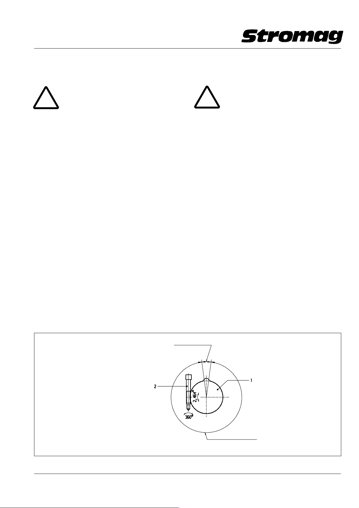
6.1 Kontakt − Einstellung (s. Bild 4)
!
Zur Kontakteinstellung ist die Haube des
Endschalters zu entfernen.
(Nur bei Gehäuseeinbau)
Vor der Schaltpunkteinstellung ist sicherzustellen,
daß die spannungsführenden Kontaktanschlüsse
durch einen Berührungsschutz bzw. bei Flachstek−
kern durch eine vollisolierte Flachsteckhülse abge−
deckt sind und es zu keiner Berührung der An−
schlüsse kommen kann.
Jedem Kontakt ist eine Nockenscheibe zugeordnet, die
stufenlos verstellbar ist. Die Nockenscheiben (1) lassen
sich, unabhängig voneinander, mit den Verstellschnek−
ken (2) einstellen. Die Einstellung kann ohne vorheriges
Lösen irgendwelcher Teile erfolgen. Die Schnecke be−
findet sich in der Selbsthemmung. Die Verstellung der
Schnecke kann mit Schraubendrehern 10 mm oder
4 mm sowie mit Innensechskantschlüssel 4 mm erfol−
gen.
Bei Rechtsdrehung der Schnecke um eine Umdrehung
(360°) erfolgt die Drehung der Nockenscheibe eben−
falls als Rechtsdrehung um 2,464° (Blick auf das Hinter−
teil, die B − Seite des Schalters).
Die Standard − Nockenscheiben sind so ausgeführt,
daß jeweils ein max. Nutzweg und ein Nachlaufweg zur
Verfügung steht (s. Getriebedaten). Nockenscheiben
mit anderen Nutzwegen können als Sonderscheiben
eingebaut werden.
Bei Überschreiten des Nachlaufweges tritt keine Be−
schädigung des Schalters ein. Es erfolgt jedoch wieder
die Öffnung oder Schließung des Kontaktes.
6 Commissioning
6.1 Contact adjustment (see Fig. 4)
!
For contact adjustment, remove the cap of
the limit switch.
(Only when mounting into a housing)
Before adjusting the switching point assure that the
live contact connection are covered by a protection
against accideantal touch or with flat plugs by a re−
ceptacle for tabs, and that touching of the connec−
tions is excluded.
An infinitely adjustable cam disc is provided for each
contact. Independently from each other, the cam discs
(1) can be set with the adjusting worm (2). It is not ne−
cessary to loosen any parts for the adjustment. The
worm is self − locked. The worm can be turned by
means of a screw driver of 10 mm or 4 mm or by means
of a hexagon socket screw key of 4 mm.
When turning the worm by one clockwise revolution
(360°), the cam disc as well is turned clockwise by
2.464° (view to the rear part, the B − side of the switch).
The standard cam discs are designed to dispose of a
max. useful travel and a max. overtravel (see gear data).
Cam discs with other useful travels can be fitted as spe−
cial discs.
When exceeding the overtravel, the switch is not dama−
ged. The contact, however, is opened or closed again.
Bild / Fig. 4
Wirksamer Nockenwinkel
Wirksamer Nockenwinkel
Effective cam angle
Effective cam angle
12
Nutzbarer Winkel der Nockenscheibe
Useful angle of the cam disc
DD − 140182
Datum / Date 10.2008
Page 14
Getriebe − Endschalter / Geared Limit Switches
Reihe / Series 51
Nr./No. 151 − 00004
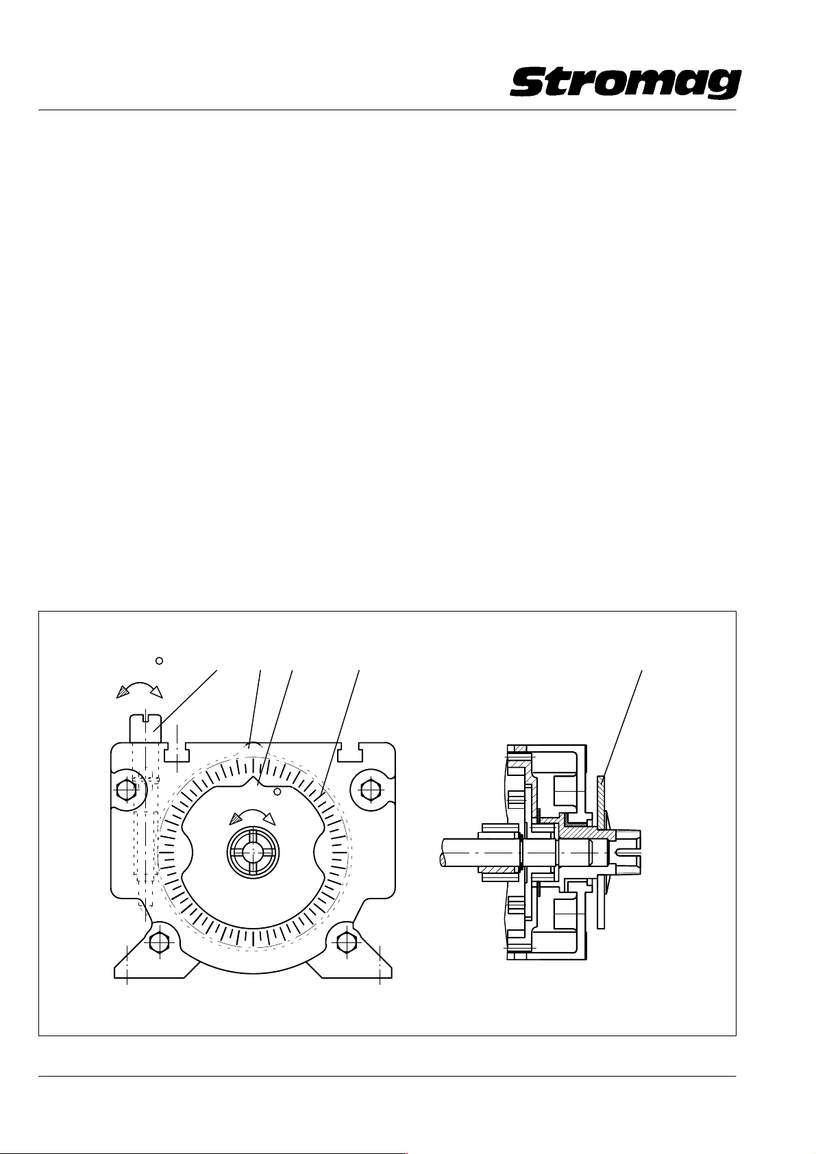
6.2 Blockverstellung (s. Bild 5)
6.2.1 Wirkungsweise
Die Bauweise des Getriebes mit Planetenstufen gibt die
Möglichkeit, ab der nutzbaren Umdrehungszahl 17,5
zusätzlich zur Einzel − Kontakteinstellung eine Block−
verstellung einzubauen. Dabei ist die letzte Getriebe−
stufe ebenfalls mit einer Verstellschnecke, jedoch in
schwarzer Farbe, ausgerüstet. Mit dieser Verstell−
schnecke (2) können alle Nockenscheiben (1) gemein−
sam verstellt werden. Dabei bleibt die relative Einstel−
lung der Einzelkontakte zueinander unverändert.
Bei Rechtsdrehung der schwarzen Schnecke um eine
Umdrehung (360°) erfolgt die Drehung der Nocken−
scheiben ebenfalls als Rechtsdrehung um 0,575° (Blick
auf das Hinterteil, die B − Seite des Schalters).
6.2.2 Zusatzausrüstung zur Blockverstellung
Mittels einer an der Rückseite (B − Seite) des Schaltes
angebauten Zeigerscheibe (3) kann die Verstellung mit
Hilfe einer Grobskala (4), 5° − Teilung, an der Rückwand
abgelesen werden. Die Zeigerscheibe zeigt die Position
der letzten Nockenscheibe an. Nach Einstellung der
letzten Nockenscheibe sollte der Zeiger (5) auf Null ge−
stellt werden. Die Scheibe ist geklemmt und kann von
Hand verdreht werden.
6.2 Block adjustment (see Fig. 5)
6.2.1 Functioning
The planetary gear construction allows a block adjust−
ment in addition to the individual contact adjustment
from the usable revolution 17.5. The final gear stage is
also provided with an adjusting worm, coloured black.
All cam discs (1) can be commonly adjusted by means
of this adjusting worm (2). The relative adjustments of
the individual contacts to each other are not modified.
When turning the black worm clockwise by one revolu−
tion (360°), the cam discs as well are turned clockwise
by 0.575° (view to the rear part, the B − side of the
switch).
6.2.2 Accessories for block adjustment
By means of an indicating plate (3), located on the rear
side (B − side) of the switch, the adjustment can be read
on a rough scale (4), 5° − graduation, at the rear panel.
The indicating plate shows the position of the last cam
disc. After adjustment of the last cam disc, the indicator
(5) shall be set to zero. The disc is jammed and can be
turned manually.
Bild / Fig. 5
360
2
1
0.575
5
4
3
DD − 140183
Datum / Date 10.2008
13
Page 15
Getriebe − Endschalter / Geared Limit Switches
Reihe / Series 51
Nr./No. 151 − 00004
7 Betrieb
!
Unabhängig von nachfolgenden Hinwei−
sen gelten für den Betrieb des Endschalters in je−
dem Falle die am Einsatzort gesetzlich vorgeschrie−
benen Sicherheits − und Unfallverhütungsvor −
schriften. Der Anwender hat für die Einhaltung die−
ser Vorschriften zu sorgen.
7.1 Betriebsbedingungen
Die Betriebsbedingungen, die für einen störungsfreien
Betrieb des Endschalters einzuhalten sind, werden
nachfolgend aufgeführt:
Die Umgebungstemperatur darf 80°C nicht überschrei−
ten und − 40°C nicht unterschreiten. Für die Typenreihe
BMC/BMK ist die Umgebungstemperatur auf max.
70°C und min. − 20°C festgelegt. Bei Bildung von Kon−
denswasser im Endschalter empfehlen wir den Einbau
einer Stillstandsheizung. Bitte nehmen Sie in solchen
Fällen Rücksprache mit unserem technischen Kunden−
dienst, Anschrift s. Kap. 10.3.
7.2 Schutzarten
Die unter Kap. 4 beschriebenen Endschalter können, je
nach Ausführung, in Schutzartgehäuse der Schutzart
IP 65 aus Aluminium oder IP55 und IP66 aus Kunststoff
montiert werden. Bei vorhandenen Gehäusen, wie
Schaltschränke usw., wird der Endschalter in Schutzart
IP 20 (Leiterplattenausführung oder Schraubanschlüs−
sen mit Berührungsschutz) für Spannungen >25V/AC
oder 60V/DC eingesetzt. Bei Spannungen <25V/AC
oder 60V/DC kann bei Schraubanschlüssen der Berüh−
rungsschutz entfallen.
Bei Kontakten mit Flachsteck − Anschlüssen s. Kap. 1.4
Kontaktanschlüsse.
Eine Übersicht über die Zuordnungen von Gehäuseart
zu den Schutzarten nach DIN 0470 − 1 / EN 60529 gibt
folgende Tabelle:
Angaben gelten nicht bei Sonderkabeleinführungen.
7 Operation
!
Independent from the following hints, the
legal safety prescriptions for prevention of accident
prescribed for the particular application case apply
to the operation of this limit switch. The user is held
responsible to adhere to these prescriptions.
7.1 Service conditions
The service conditions to be adhered to in order to en−
sure a faultless operation of the limit switch, are listed
below:
The ambient temperature must not exceed 80°C and
must not fall below − 40°C. For the series BMC/BMK,
the ambient temperature is fixed to max. 70°C and min.
− 20°C. In case of condensation water generation in the
limit switch, we recommend to fit a standstill heating. In
these cases, please consult our technical after − sales
service; address as per chap. 10.3.
7.2 Types of protection
In relation to the execution, the limit switches described
in chapter 4 can be mounted in a protective housing of
protection class IP 65 of aluminium or IP55 and IP66 of
synthetic material. With already existing housings, such
as switch cabinets, etc., the limit switch is used in pro−
tection class IP 20 (printed card execution or screw ter−
minals with protection against accidental touch) for vol−
tages >25V/AC or 60V/DC. With voltages <25V/AC or
60V/DC the protection against accidental touch for
screw terminals can be omitted.
For contacts with flat plugs see chap. 1.4 contact con−
nections.
A list of housing types co − ordinated to the type of pro−
tection as per DIN 0470 − 1 / EN 60529 is given in the fol−
lowing table:
The statements do not apply to special cables inlets.
Ohne Gehäuse,
ohne Berührungsschutz nur für Spannung
<25V/AC bzw. 60V/DC,
mit Schraub − oder Steckanschlüssen
Ohne Gehäuse,
Kontakte auf Leiterplatte oder mit Be −
rührungsschutz
Kunststoff − Gehäuse
Ausführung B3/B14/B5
Kunststoff − Gehäuse C/K
Ausführung B14/B5
Das Gehäuse ist nicht für Außeneinsatz zu
verwenden
Alu − Gehäuse
Ausführung B3/B14
IP 00
IP 20
IP 66
IP 55
IP 65
14
Without housing,
without protection against accidental touch
only for voltage <25V/AC or 60V/DC,
with screw terminal or plugs
Without housing,
contacts on printed card or with protection
against accidental touch
Housing of synthetic material
execution B3/B14/B5
Housing of synthetic material C/K
execution B14/B5
The housing is not suitable for outdoor ap−
plication
Aluminium housing
execution B3/B14
Datum / Date 10.2008
IP 00
IP 20
IP 66
IP 55
IP 65
Page 16
Getriebe − Endschalter / Geared Limit Switches
Reihe / Series 51
Nr./No. 151 − 00004
8 Instandhaltung
Bei Wartungs − und Inspektionsarbeiten ist das Kapitel
2 "Sicherheitshinweise" zu beachten.
Grundsätzlich sind keine Wartungs − oder Inspektions−
arbeiten am Getriebe − Endschalter erforderlich.
Staubablagerungen auf Endschaltern der Schutzart
IP 00, IP 20 oder bei geöffnetem Schutzartgehäuse dür−
fen auf keinen Fall mit Preßluft entfernt werden, da der
Staub dadurch erst recht in die Kontakte eindringen
und das Schaltvermögen beeinträchtigen kann.
Die Haubendichtungen der Schutzartgehäuse, sind
nach dem Öffnen der Haube nach längerer Betriebszeit
zu erneuern.
Achtung!
Auf keinen Fall darf für die Reinigung
des Endschalters Benzin oder andere Lösungsmit−
tel verwendet werden.
9 Sonderausführungen
9.1 Ausführung mit anderen Nockenwinkeln
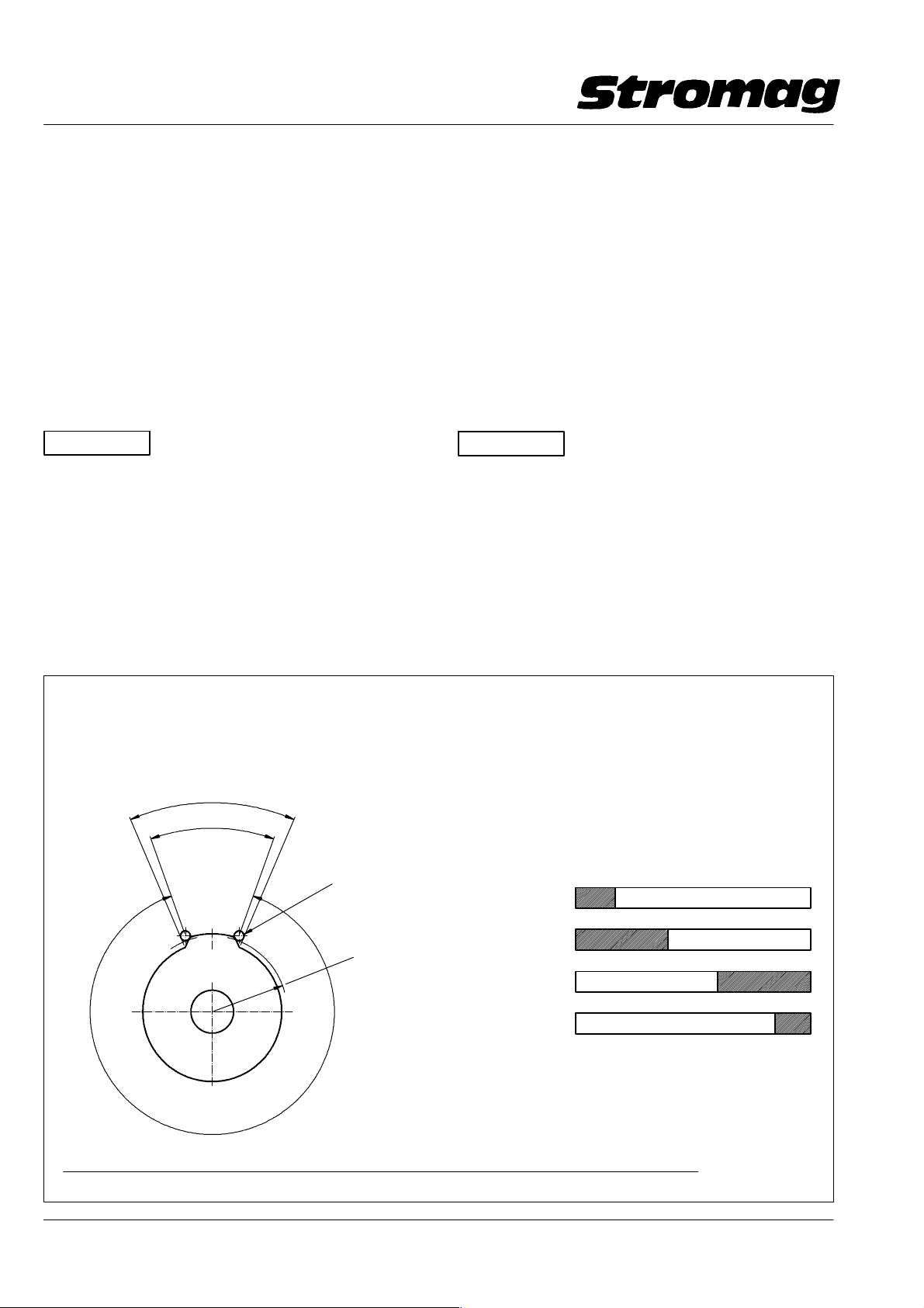
Auf Wunsch können beliebige Nockenwinkel
(15° − 360°) als Sonderausführung geliefert werden.
Siehe hierzu folgende Beispiel − Zeichnung:
8 Maintenance
When carrying − out maintenance and inspection
works, pay attention to chapter 2 "Safety guide − lines".
Generally no maintenance or inspection works at the
geared limit switch are necessary.
Do not remove dust deposits on the limit switches of
protection IP 00, IP 20 or with open protective housings
by means of compressed air. The dust would penetrate
into the contacts and would affect the switching capa−
city.
The cap − type sealings of the protective housings have
to be replaced after opening of the cap and a longer
operation time.
Caution!
Do not use benzine or any other sol−
vent for cleaning of the limit switch.
9 Special executions
9.1 Execution with various cam angles
On request various cam angles (15° to 360°) can be
supplied as special execution. See the following exam−
ple:
Die Nockenscheiben werden nach dem wirksamen Nockenwinkel benannt.
Bei Nockenscheiben der Reihe 51 entspricht dieser dem
Schaltpunktwinkel auf dem Schaltpunktradius der Nockenscheibe.
Der Fertigungswinkel ergibt sich aus der Konstruktion der Nockenscheibe.
Fertigungswinkel/Production angle
Wirksamer − Nockenwinkel
Effective cam angle
(Schaltpunktwinkel)
(Switching point angle)
Rollenhebel des Schaltkontaktes
Roller lever of switching contact
Schaltpunkt − Radius
Switching point radius
Nutzbarer Winkel
der Nockenscheibe
Usable angle of cam disc
Die nutzbaren Umdrehungen, die eine Nockenscheibe
an der Antriebswelle eines Getriebeschalters ermöglicht, ergibt sich folgendermaßen:
The usable number of revolutions of the drive shaft
of a geared switch enabled by a cam disc can be calculated as follows:
The cam discs are designated according to their effective cam angle.
With 51 series cam discs, this corresponds to the switching point
angle on the switching point radius of the cam disc.
The production angle results from the design of the cam disc.
Beispielzeichnung
Example drawing
Kontakt / Contact Nockenwinkel / Cam angle _
0 15 60 270 315 360
1
2
3
4
(360_ − α (wirksamer Nockenwinkel/effective cam angle) x i (Getriebeuntersetzung des Schalters/gear reduction of switch)
360°
Datum / Date 10.2008
15
DD1_40294V
DD − _140184
Page 17

Getriebe − Endschalter / Geared Limit Switches
Reihe / Series 51
Nr./No. 151 − 00004
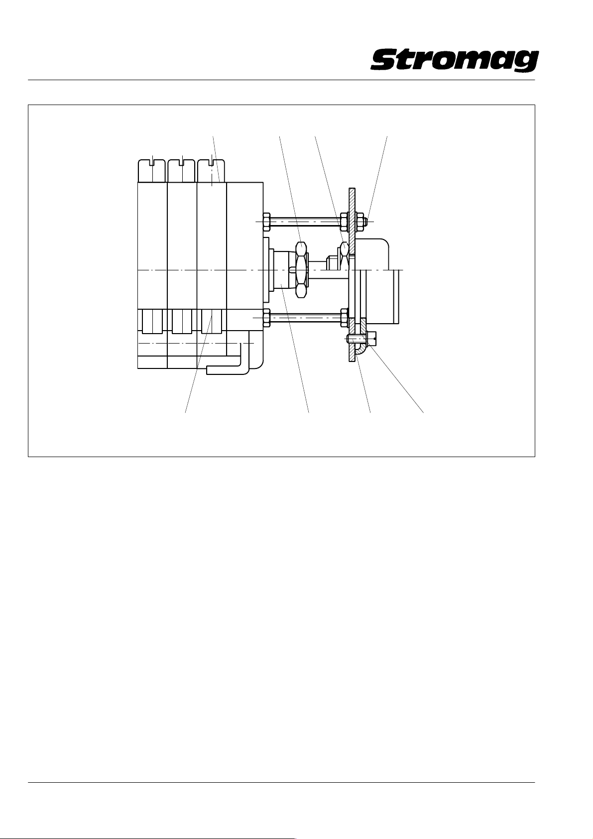
9.2 Ausführung mit zusätzlichem Drehwiderstand
Der Anbau von Drehwiderständen an der B − Seite des
Endschalters zur analogen Stellungsrückmeldung ist in
2 Ausführungen möglich (s. hierzu Bild 6.).
Ausführung "N"
Drehwinkel max. 345°, synchron mit Drehung der Nok−
kenscheiben.
Ausführung "S"
Drehwinkel max. ~ 1470° (345° x 4,285) zum Antrieb
von Mehrfach − Wendel − Potentiometern.
Der Antrieb erfolgt über eine Kupplung mit einer 6 mm
Bohrung (nur Drehwiderstände mit 6 mm Wellendurch−
messer verwenden).
Der Drehwiderstand ist je nach Ausführung an einem
Stützblech (3), mit einer Klemmutter (4) oder mit Ser−
vo − Klammern (5) befestigt.
Die Abstandsbolzen (6) dienen als Drehmomentstütze
und verbinden die Schalterrückwand mit dem Stütz−
blech (3). Bei Verwendung von Drehwiderständen mit
Klemmutter (4) kann diese durch Lösen und Verdrehen
des Widerstandshäuses zur Einstellung benutzt wer−
den. Bei Verwendung von Servo − Klammern (5) wer−
den diese gelöst. Die Einstellung erfolgt ebenfalls durch
Verdrehung des Widerstandshäuses.
9.2 Execution with additional resistor
The resistors for analogous position feedback can be
mounted to the B − side of the limit switch in two different
ways (see Fig. 6).
Execution "N"
Max. twisting angle 345°, synchronous with the revolu−
tions of the cam discs.
Execution "S"
Max. twisting angle ~ 1470° (345° x 4.285) to drive mul−
titurn potentiometers.
The drive is transmitted by a coupling with a 6 mm bore
(use resistors with 6 mm shaft dia. only).
In relation to the execution, the resistor is fixed to a sup−
porting sheet (3) either by a tightening nut (4) or by ser−
voclamps (5).
The distance bolts (6) serve as torque support and con−
nect the switch back panel to the supporting sheet me−
tal (3). When using resistors with tightening nut (4), this
nut can be used for adjustment by loosening and tur−
ning of the resistor housing. When using servoclamps
(5), these ones are loosened. The adjustment is also
made by turning of the resistor housing.
Bei Befestigungsarten, bei denen sich das Wider−
standsgehäuse nicht verdrehen läßt, wird die Mutter (1)
auf der Kupplung (2) gelöst. Danach wird die Welle mit
Hilfe einer Zange o.ä. zur Einstellung verdreht.
Nach der Einstellung sind alle Muttern bzw. Schrauben
wieder anzuziehen.
Ist für die Widerstandseinstellung eine zusätzliche Nok−
kenscheibengruppe (7), an der letzten Position vom An−
trieb aus gesehen, eingebaut, so erfolgt die Einstellung
des Drehwiderstandes mit der Verstellschnecke (8) die−
ser zusätzlichen Nockenscheibengruppe ohne das Lö−
sen von Schrauben oder Muttern.
Eine vorhandene Blockverstellung wirkt wie bei den
Nockengruppen für die Kontakte auch auf die letzte
Nockenscheibengruppe für die Widerstandseinstel−
lung.
Bei einer Korrekturverstellung der Schalterpunkte mit−
tels der Blockverstellung verstellt sich im gleichen Maße
die Potieinstellung.
Die Widerstandseinstellung mit zusätzlicher Nocken−
scheibengruppe kann nur in Ausführung "N" erfolgen.
In case of fixations not allowing to turn the resistor hou−
sing, the nut (1) on the coupling (2) is loosened. The−
reafter the shaft is turned for adjustment by means of
pincers or similar.
After adjustment, all nuts or screws resp. have to be re −
tightened.
If an additional cam disc assy (7) is fitted to the last posi−
tion (view from the drive) for adjustment of the resistor,
the adjustment of the resistor is made by the adjusting
worm (8) of this additional cam disc assy without having
to loosen the screws or nuts.
An available block adjustment also acts on the last cam
disc assy for resistor adjustment, just as for the contact
cam discs.
When making a corrective adjustment of the switch
points by means of block adjustment, the potentiome−
ter adjustment changes accordingly.
The resistor adjustment with additional cam disc assy
is only possible in execution "N".
16
Datum / Date 10.2008
Page 18
Getriebe − Endschalter / Geared Limit Switches
Reihe / Series 51
Nr./No. 151 − 00004
8
14 6
Bild / Fig. 6
7235
9.3 Ausführung mit durchgehender Antriebswelle
Durchführung der Antriebswelle zum Antrieb von Inkre−
mental − oder Absolut − Encodern, synchron zur An−
triebsdrehzahl.
Als Sonderkonstruktion wird die Antriebswelle durch
die Lagerplatte zum Antrieb von Inkremental − oder Ab−
solut − Encodern geführt. Aus konstruktiven Gründen
befindert sich der Encoder hinter der Lagerplatte und
dem Kontaktblock, zwecks Synchronlauf zur Antriebs−
drehzahl.
9.4 Ausführung mit Heizwiderstand
Zur Vermeidung von Kondenswasser kann im Schalter−
raum ein Heizwiderstand eingebaut werden. Diese Hei−
zung ist so ausgelegt, daß eine Heizleistung je nach
Spannung von ca. 2,5 Watt bzw. 4 Watt zur Verfügung
steht. Die entsprechende Versorgungsspannung
12 − 36V AC/DC oder 110 − 250V AC/DC nach Bestel−
lung. Die PTC − Heizung ist selbstregelnd und tempera−
turbegrenzend und führt somit zu einer selbsttätigen
Anpassung an die Umgebungstemperatur. Der An−
schluß erfolgt über eine 2 − polige Klemmleiste.
DD − 140185
9.3 Execution with through input shaft
The input shaft can be extended through to allow dri−
ving of incremental or absolute value encoders syn−
chronous to the driving speed.
As special design, the input shaft is conducted through
the bearing plate to the drive of an incremental or abso−
lute value encoder. For constructional reasons the en−
coder is located behind the bearing plate and the con−
tact block to assure synchronous run to the driving
speed.
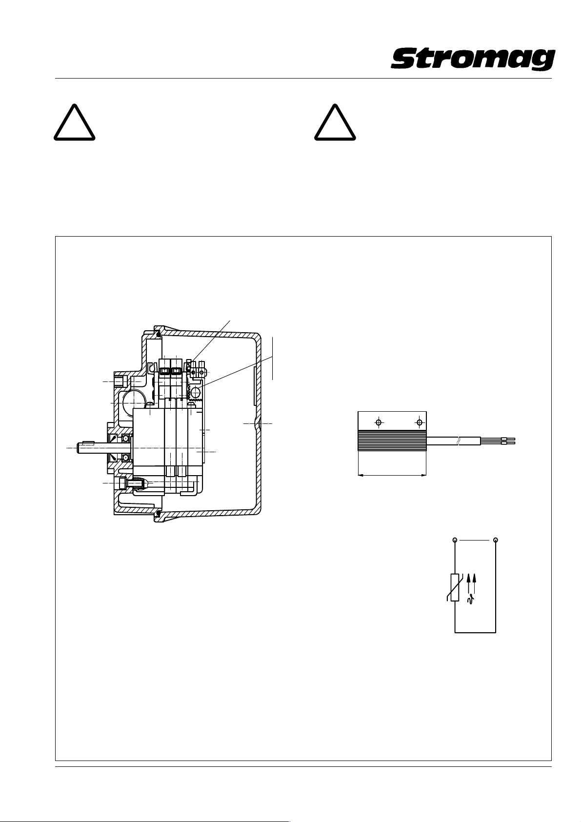
9.4 Execution with heating resistor
To avoid the generation of condensation water a heat−
ing resistor can be fitted in the switch space. This heat−
ing is designed to dispose of a heating output of approx.
2.5 watts or 4 watts in relation to the voltage. The corre−
sponding supply voltage is 12 − 36 volts a.c./d.c. or
110 − 250 volts a.c./d.c. as per order. The PTC heating
is self − regulating and temperature limiting thus result−
ing in an automatic adaption to the ambient tempera−
ture. The connection is made through a two − pole ter−
minal strip.
Datum / Date 10.2008
17
Page 19
Getriebe − Endschalter / Geared Limit Switches
Reihe / Series 51
Nr./No. 151 − 00004
!
Die Oberfläche der Heizung kann sich auf
ca. 60_C erwärmen.
Der Heizwiderstand und die Klemmenleiste werden an
einem Tragblech an der Rückwand des Schalters mit
M3 Schrauben und Muttern befestigt, s. Bild 7.
Beispiel für den Einbau einer PTC − Heizung in ein IP66 Gehäuse
Example of installation of a PTC heater in an IP66 housing
Anschlußklemme/Connection terminal
PTC − Heizungsgruppe/PTC heater assembly
für/for 12 − 36V AC/DC, P ca./approx. 2.5 Watt
oder/or 110 − 250V AC/DC, P ca./approx. 4 Watt
!
The surface of the heater can reach a tem−
perature of approx. 60_C.
The heating resistor and the terminal strip are fixed to
a supporting sheet at the rear panel of the switch by
means of screws M3 and nuts, see fig. 7.
PTC − Heizung/Heater
DD1_40285V
Ausführung/Execution: U
Heizleistung/Heating cap.: ca. 2.5 Watt ca. 4 Watt
(im ausgeregelten Zustand/in levelled condition)
Kaltwiderstand PTC (bei 25_C)
Cold resistance PTC: R25 20 ± 35% R25 1500 ± 35%
PTC − Bezugstemperatur:
PTC ref. temperature: 50_C50_C
Schutzklasse
Protection (VDE 0100, 0160): II II
Anschlußleitung: 2x0.25mm2, Silikonkabel 2x0.25mm2, Silikonkabel
Connection cable: 2x0.25mm2, Siliconecable 2x0.25mm2, Siliconecable
Heizkörper/Radiator: Aluminium eloxiert/eloxed Aluminium eloxiert/eloxed
Gewicht / Weight: ca. 40 g ca 40 g
Bild / Fig. 7
12 − 36V AC/DC 110 − 250V AC/DC
B
50
Ersatzschaltbild
Equivalent wiring diagram
12
*
U
B
PTC
*Anschlußspannung je nach ver −
wendeter Variante 12 − 36V AC/DC
bzw. 110 − 250V AC/DC
Connection voltage in relation to the
variant used 12 − 36V AC/DC
or 110 − 250V AC/DC
DD1_ 40298V
18
Datum / Date 10.2008
Page 20
Getriebe − Endschalter / Geared Limit Switches
Reihe / Series 51
Nr./No. 151 − 00004
10 Ersatzteilhaltung und Kundendienst
10.1 Ersatzteilhaltung
Der Endschalter ist so konstruiert, daß es keine Teile mit
besonders hohem Verschleißverhalten unter den Ein−
satzbedingungen gem. Kap. 7.1 gibt.
Der Endschalter ist so konstruiert, daß er bei Einhaltung
der Betriebsbedingungen gem. Kap. 7.1 eine hohe Le−
bensdauer erzielt.
Sollte es wider erwarten doch einmal erforderlich sein,
ein Teil gegen ein neues Teil zu ersetzen, so kann dieses
mittels einer Ersatzteilliste identifiziert werden. Die Er−
satzteilliste kann von unserem technischen Kunden−
dienst angefordert werden, Anschrift s. Kap. 10.3.
Aus Sicherheitsgründen empfehlen wir jedoch den
kompletten Schalter zur Reparatur an uns zu senden.
10.2 Daten für die Ersatzteilbestellung und Rückfra−
gen
Zur Ersatzteilbestellung bedienen Sie sich bitte der an−
zufordernden Ersatzteilliste.
Es sind folgende Angaben erforderlich:
Auftrags − Nr. s. Kap. 1.1
Baureihe u. Größe s. Kap. 1.1
Typ s. Kap. 1.1
Position und Benennung
des Ersatzteiles
Stückzahl
s. Ersatzteilliste
10 Spare parts stocking and after − sales ser−
vice
10.1 Spare parts stocking
The construction of the limit switch does not include
parts strongly subjected to wear, provided that it is used
under the prescribed application conditions as per
chapter 7.1.
When adhering to the prescribed operation conditions,
as per chapter 7.1, the limit switch reaches a long life−
time.
Nevertheless, should it become necessary to replace
any part by a new one, the part concerned can be identi−
fied by a spare parts list. Please ask our technical after −
sales service for this spare parts list, address is given in
chap. 10.3.
For reasons of safety, however, we recommend to re−
turn the complete switch to us for repair.
10.2 Data for spare parts orders and inquiries
When ordering spare parts please refer to the spare
parts list to be inquired.
The following information is required:
Order − Ref. − No. see chap. 1.1
Series and Size see chap. 1.1
Type see chap. 1.1
Item − number and designa −
tion of the spare part
Quantity
see spare parts
list
10.3 Kundendienstanschrift
Unsere Anschrift für den Kundendienst und den Ersatz−
teilvertrieb:
Stromag AG
59411 Unna, Postfach 2123
59425 Unna, Hansastr. 120
Telefon (02303) 102 − 225 / − 336
Telefax (02303) 102 − 437
Benötigen Sie einen Service − Monteur, so wenden Sie
sich unter obiger Telefon − Nummer an uns.
10.3 Address of our after − sales service
The address of our after − sales service and the sales of
spare parts is:
Stromag AG
D − 59411 Unna, Postfach 2123
D − 59425 Unna, Hansastr. 120
Telephone (02303) 102 − 225 / − 336
Telefax (02303) 102 − 437
Do you need the delegation of a service engineer?
Please contact us under our above telephone number.
Datum / Date 10.2008
19
Page 21
Getriebe − Endschalter / Geared Limit Switches
Reihe / Series 51
Nr./No. 151 − 00004
11 Entsorgungshinweis
Sollten Sie Fragen zur umweltverträglichen Entsorgung
des Stromag − Produktes nach Wegfall der Nutzung ha−
ben oder Hilfestellung zu diesem Thema benötigen, so
steht Ihnen der Umweltbeauftragte der Stromag AG als
Ansprechpartner zur Verfügung. Wenden Sie sich bitte
an unseren Kundendienst, Anschrift s. Kap. 9.3.
11 Hints for waste management
The environmental representative of Stromag AG is at
your disposal to answer to your questions regarding the
environmentally friendly waste management of Stro−
mag products after their utilisation or to grant you any
assistance required. Please consult our after − sales
service; address as per chap. 9.3.
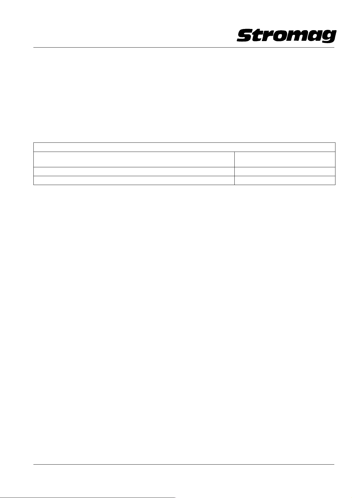
12 Aufgeführte Normen und Richtlinien / Listed standards and regulations
Der Endschalter entspricht den einschlägigen Normen und Richtlinien, insbesondere folgenden:
The limit switch comply with the usual standards and regulations, in particular with:
Titel / Title
Errichten von Starkstromanlagen mit Nennspannungen bis 1000 V
Erection of power installations with nominal voltages up to 1000 volts
Niederspannug − Schaltgeräte / Low − voltage switching devices EN 60947 − 5 − 1
Schutzarten durch Gehäuse / Protections by housing DIN VDE 0470 − 1 / EN 60529
DIN VDE 0100
20
Datum / Date 10.2008
 Loading...