

Page 1
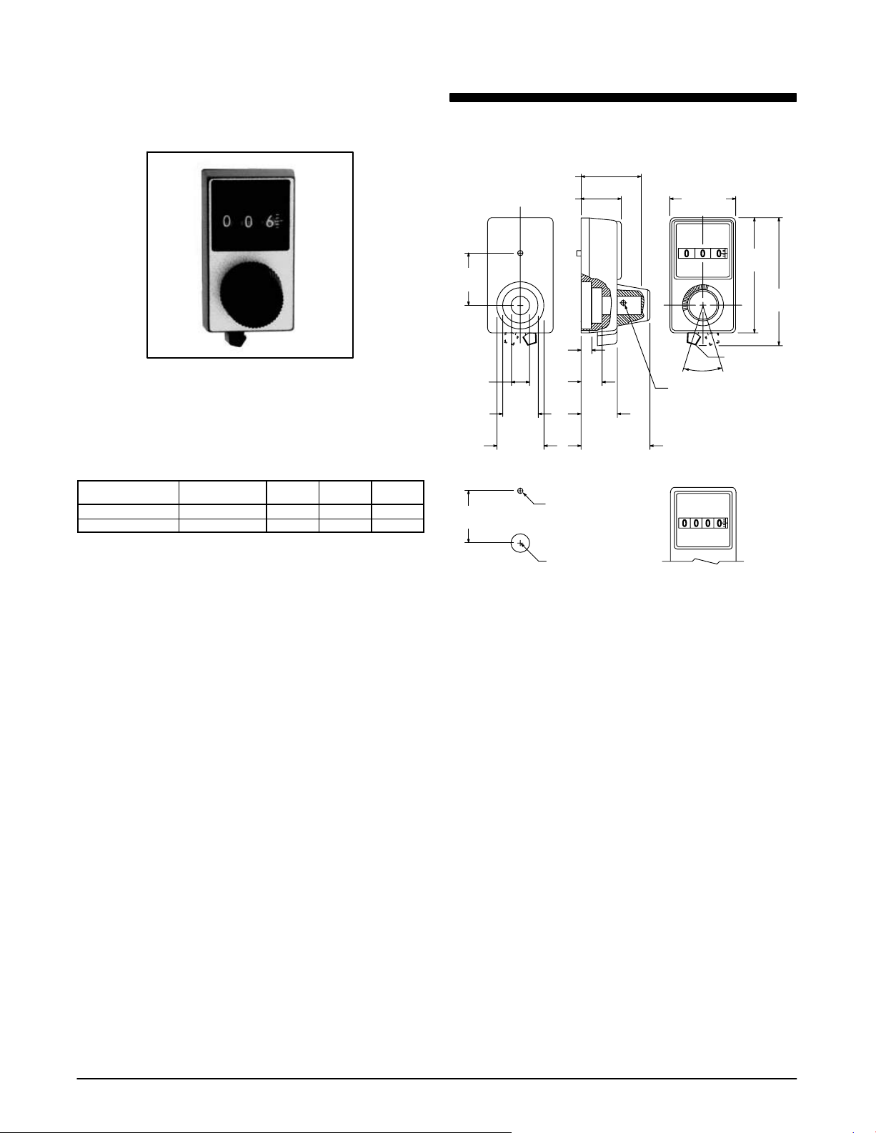
Features
• 3 digit or 4 digit types
• 2 No. 4−40 hex socket set screws for mounting
• Brake lever knob
• Open window display
• Satin clear anodize finish
Spectrol Model 15
Dial − 1” x 1 3/4” rectangular, 1/4” dia
shaft
Spectrol No. NTE Part No.
15−1−11 503−0001 3 Digit 10 D1
15−2−11 503−0002 4 Digit 100 D1
Numeric
Display
No. of
Turns
Diag
No.
D1
.750
(19.05)
.250
(6.35)
Dia
.750
(19.05)
.812 (20.62) Min
.640 (16.26)
.175
(4.45)
.333
(8.46)
.495
(12.57)
Dia
.695
(17.65)
Dia
.128 (3.25) Dia
(No. 30 Drill)
C Component Shaft Hole
L
.530
(13.46)
1.060 (26.92)
Max
1.000
(25.4)
Travel
OFF
Set Screws (2 Places)
90° Apart
4 Wheel VersionMounting Hole Pattern
1.750
(44.45)
1.950
(49.53)
Brake Lever Knob
ON
Specifications
Operation
3 Digit (10 turn): The left digit indicates the number of complete
revolutions of the turning knob and the right two digits indicate the
percent of a revolution. The unit registers a total count of 999.
4 Digit (100 turn): The left two digits indicate the number of complete
revolutions of the turning knob and the right two digits indicate the
percent of a revolution. The unit registers a total count of 9999.
Minor Scale Division: 1/500 turn
Indication: 0 to 9.99 turn (3 Digit), 0 to 99.99 (4 Digit)
Accuracy: ±0.2% of knob position
Rotation: The indication shall increase with clockwise rotation.
Transfer Point: between 9.2 and 0
Mechanical
Shaft Bore: 0.250”
Runout: 0.004 in/in (Note 1)
Mounting: The spring detented knob shall be removed using a straight
pull, exposing two No. 4−40 hex socket set screws for mounting the dial
directly to the component shaft (hex key included).
Note 1. Dial to be free running and without binds when axis of drive
sleeve is perpendicular to mounting surface within the
specified dimension.
NTE Electronics, Inc. D Voice (973) 748−5089 D FAX (973) 748−6224 D http://www.nteinc.com
31
Page 2
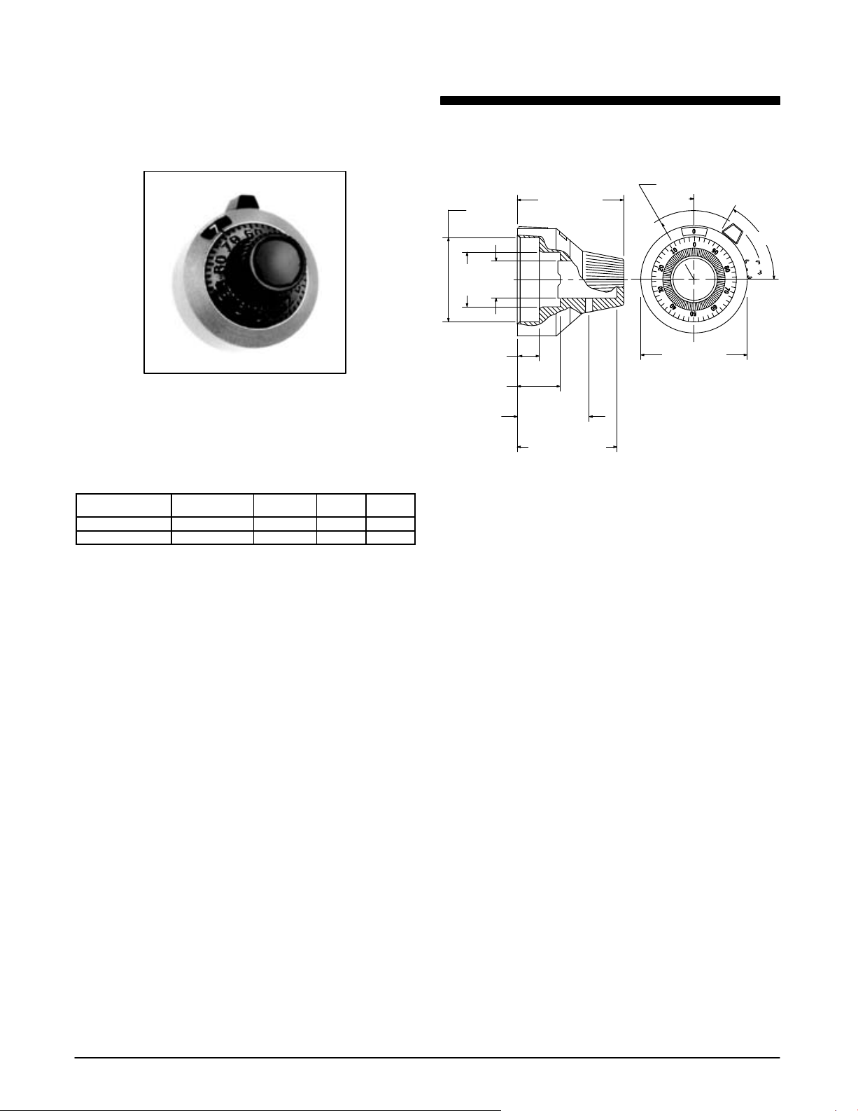
Features
• Vernier Scale
• No. 2−56 Spline Socket Set Screw for Mounting
• Brake Lever Knob
• Open Window Display
• Available in Two Finish Types:
Satin Chrome Finish, Black Markings (503−0004)
Black Chrome Finish, White Markings (503−0005)
Spectrol Model 16
Dial − 7/8” diameter, 1/4” dia shaft
NEW
Spectrol No. NTE Part No.
16−1−11 503−0004 Vernier Scale 15 D2
16−1−21 503−0005 Vernier Scale 15 D2
Numeric
Display
No. of
Turns
Diag
No.
D2
(10.41)
.410
.625
(15.88)
Dia
(6.35)
Dia
.155 (3.94)
.310 (7.87)
.875 (22.22)
.250
Dia
.562 (14.27)
.812 (20.62) Min
.562 (14.27) R
30°
50°
.875 (22.22)
Note: Mountin bracket may vry
Specifications
Operation
Readout and Operation: Unit shall register a total count of 15 turns.
The number in the window (0 thru 14) indicates completed number of
turns of the drive sleeve. Graduated circular dial indicates the percent
of a partial turn of the drive sleeve.
Minor Scale Division: 1/50 turn
Indication: 0 to 14.99 turn
Brake Lever: 1st position (15° movement of brake lever) operates a
high torque system for fine adjustment; 2nd position (15° additional
movement of brake lever) actuates brake.
Accuracy: Backlash shall be zero between graduated dial and drive
sleeve
Rotation: The indication shall increase with clockwise and decrease
with a counterclockwise rotation.
Transfer Point: The number in the center of the window shall
change as graduated dial rotates between 94 and 0.
Mechanical
Shaft Bore: 0.250”
Runout: 0.004 in/in (Note 1)
Mounting: Install mounting bracket (included) between panel and
panel nut. Multidial shall mount directly to shaft with No. 2−56 spline
socket set screw, located adjacent to No. 50 on graduated dial (hex key
included).
32
Note 1. Dial to be free running and without binds when axis of drive
sleeve is perpendicular to mounting surface within the
specified dimension.
NTE Electronics, Inc. D Voice (973) 748−5089 D FAX (973) 748−6224 D http://www.nteinc.com
Page 3
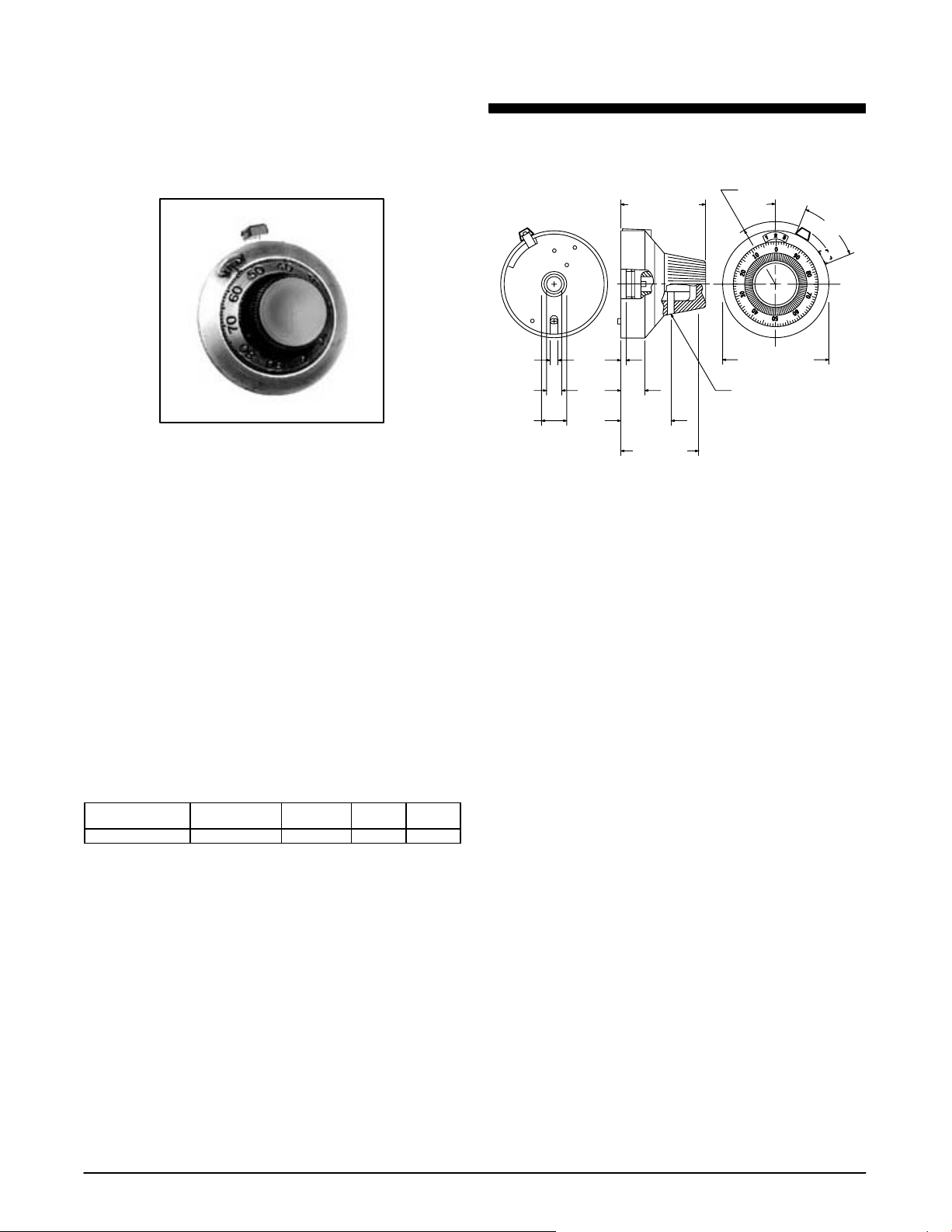
Features
• Vernier scale
• No. 4−40 hex socket set screw for mounting
• Brake lever knob
• Open window display
• Satin chrome finish, black markings
Spectrol Model 21
Dial − 1 13/16” diameter, 1/4” dia
shaft
D3
1.000 (25.4)
1.094 (27.79) R Max
22°
46°
Spectrol No. NTE Part No.
21−1−11 503−0006 Vernier Scale 15 D3
Numeric
Display
No. of
Turns
Diag
No.
.125
(3.18)
.250
(6.35)
.390
(9.91)
.128
(3.25)
.268
(6.81)
.578
(14.68)
(23.42)
.922
1.812 (46.02)
Dia
Set Screw
(At No. 75 on Dial Face)
Specifications
Operation
Readout and Operation: Unit shall register a total count of 1499. The
number in the center of the window (0 thru 14) indicates completed
number of turns of the drive sleeve. Graduated circular dial indicates
the percent of a partial turn of the drive sleeve.
Minor Scale Division: 1/100 turn
Indication: 0 to 14.99 turn
Accuracy: Backlash shall be zero between graduated dial and drive
sleeve
Rotation: The indication shall increase with clockwise and decrease
with a counterclockwise rotation.
Transfer Point: The number in the center of the window shall
change as graduated dial rotates between 94 and 0.
Mechanical
Shaft Bore: 0.250”
Runout: 0.004 in/in (Note 1)
Mounting: Unit shall mount directly to shaft with No. 4−40 hex socket
set screw, located adjacent to No. 75 on graduated dial (hex key
included).
Note 1. Dial to be free running and without binds when axis of drive
sleeve is perpendicular to mounting surface within the
specified dimension.
NTE Electronics, Inc. D Voice (973) 748−5089 D FAX (973) 748−6224 D http://www.nteinc.com
33
Page 4

Features
• Vernier scale
• Black anodized
aluminum (clear) anodized w/black markings
• Available with or without brake lever
w
/white markings or natural
KILO 400 Series
Dial − 1” diameter, 1/4” dia shaft,
aluminum
Numeric
KILO No. NTE Part No.
411 505−0001 Vernier 10 No Black D4
412 505−0002 Vernier 10 Ye s Black D4
461 505−0003 Vernier 10 No Clear D4
462 505−0004 Vernier 10 Ye s Clear D4
Display
No. of
Turns
Brake
Lever
Finish
Diag
No.
D4
1.000 (25.4) Max
1.000
(25.4)
Max
Specifications
Mechanical
1” Multi−turn dials feature easy to read primary and secondary scale,
absolutely zero backlash because the index line and brake elements
are secured to the panel without locating lugs and holes.
Requires only one square inch of panel space.
Shaft Bore: 0.250”
Shaft Extension Beyond Face of Panel: .600” Min, .800 Max
Bushing Extension Beyond Face of Panel: .125” Min, .297” Max
thread (full thread)
 Loading...