

Page 1
Surface Mount Fuses
Ceramic Fuse > 501 Series
501 Series – High Current 1206 Fast-Acting Fuse
Description
The 501 Series is a 100% Lead-free, RoHS compliant and
Halogen-free fuse series designed specifically to provide
over- current protection to circuits that operate under high
working ambient temperature up to 150°C.
The general design ensures excellent temperature stability
and performance reliability.
2
The high I
t values which is typical in the Littelfuse
Ceramic Fuse family, ensure high inrush current withstand
capability.
Features
• 100%Lead-free,RoHS
compliant and Halogenfree
• Suitableforbothleaded
and lead-free reflow /
wave soldering
• NotebookPC
• DC-DCConverter
Agency Approvals
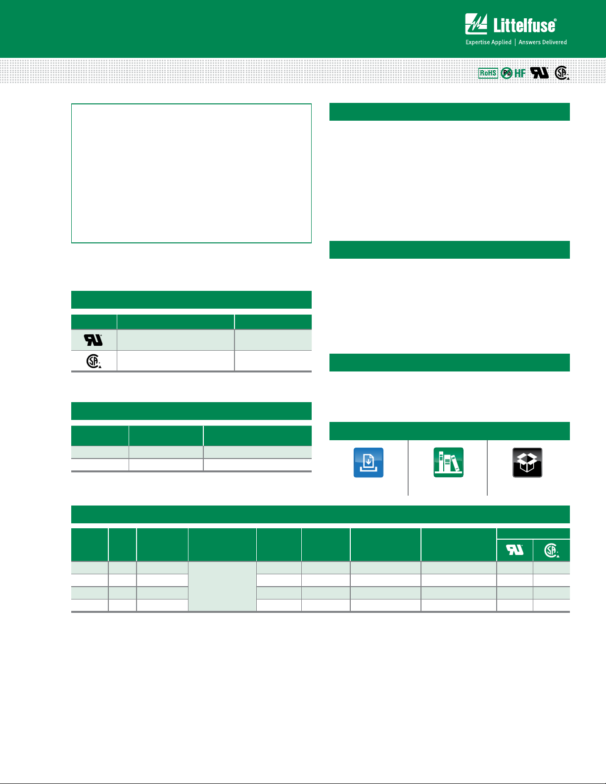
AGENCY AGENCY FILE NUMBER AMPERE RANGE
E10480 10A - 20A
LR29862 10A - 20A
• OperatingTemperature
from -55ºC to +150ºC
• Designedtoprovide
over-current protection
in high current voltage
regulator module (VRM)
applications
Applications
• VoltageRegulator
Module (VRM)
Equipment
Electrical Characteristics for Series
% of Ampere
Rating
100% 10A – 20A 4 Hours, Minimum
350% 10A – 20A 5 Seconds, Maximum
Ampere Rating Opening Time at 25ºC
Additional Information
Datasheet
Resources
Samples
Electrical Specifications by Item
Ampere
Rating
(A)
10 010. 32
12 012. 32 0.00321 20.341 0.04891 0.5870 x x
15 015. 32 0.00250 36.100 0.04605 0.6908 x x
20 020. 32 0.00200 54.760 0.05936 1.1871 x x
Notes:
1. DC Interrupting Rating tested at rated voltage with time constant < 0.5 msec.
2. Nominal Resistance measured with < 10% rated current.
3. Nominal Melting I
4. Nominal Voltage Drop measured at rated current after temperature has stabilized and
with fuse mounted on board with 3-oz Cu trace.
Max. Voltage
Amp
Code
Rating
(V)
2
t measured at 1 msec. opening time. For other I2t data refer to chart.
Interrupting
Rating
1
(DC)
150 A @ 32 VDC
Nominal
Resistance
(Ohms)
0.00427 10.385 0.05679 0.5679 x x
Nominal
Melting I2T
2
(A2Sec.)
Nominal Voltage
Drop At Rated
3
Current (V)
Devices designed to carry rated current for 4 hours minimum. It is recommended that
devices be operated continuously at no more than 80% rated current. See “Temperature
Rerating Curve”for additional rerating information.
Devices designed to be mounted with marking code facing up.
Nominal Power
Dissipation At
4
Rated Current (W)
Agency Approvals
© 2013 Littelfuse, Inc.
Specifications are subject to change without notice.
Revised: 12/19/13
Page 2
Surface Mount Fuses
Ceramic Fuse > 501 Series
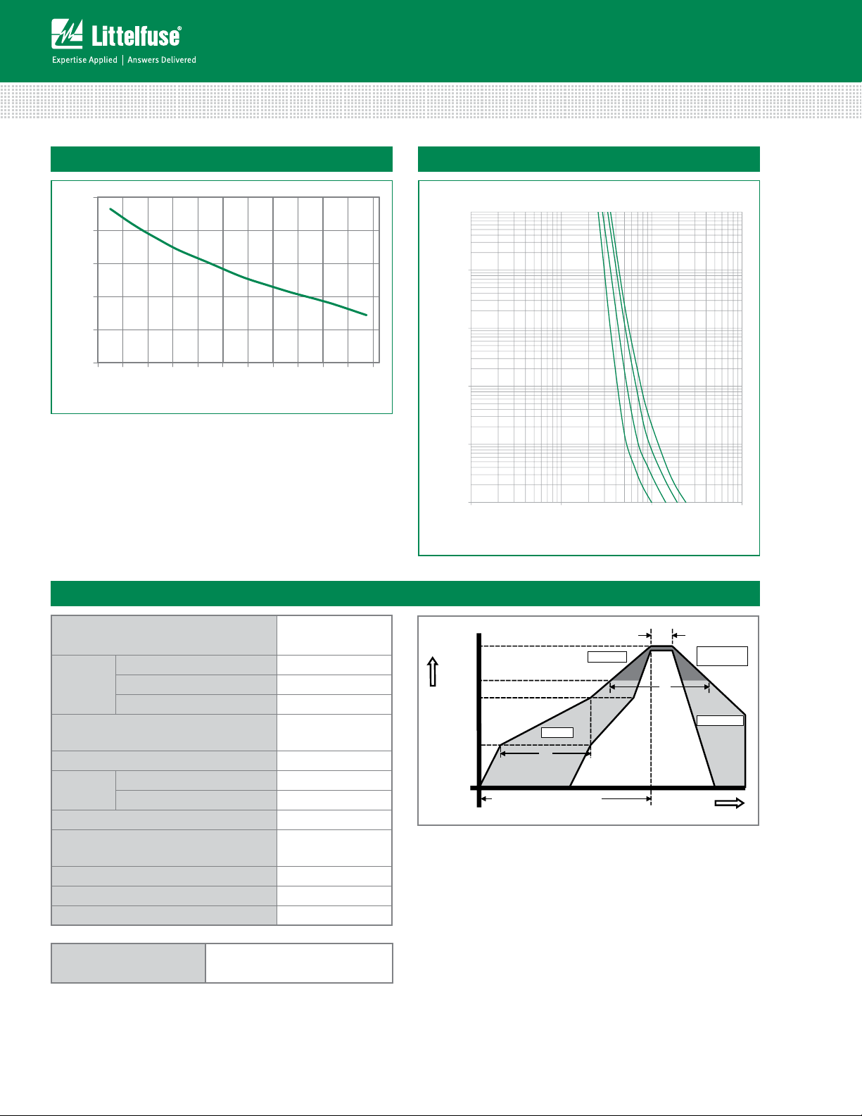
Temperature Rerating Curve
140
120
100
80
PERCENT OF RATING
60
40
-65 -45 -25 -5 15 35 55 75 95 115 135 155
TEMPERATURE (°C)
Note:
1. Rerating depicted in this curve is in addition to the standard rerating of 20% for
continuous operation.
Example:
For continuous operation at 75 degrees celsius, the fuse should be rerated as follows:
I = (0.80)(0.85)I
RAT
= (0.68)I
RAT
Average Time Current Curves
10
1
0.1
TIME IN SECONDS
0.01
0.001
1 10 100 1000
CURRENT IN AMPERES
15A
10A
12A
20A
Soldering Parameters
Reflow Condition Pb – free assembly
- Temperature Min (T
Pre Heat
- Temperature Max (T
- Time (Min to Max) (ts) 60 – 180 seconds
Average Ramp-up Rate (Liquidus Temp
(T
) to peak)
L
to TL - Ramp-up Rate 5°C/second max.
T
S(max)
Reflow
- Temperature (TL) (Liquidus) 217°C
- Temperature (tL) 60 – 150 seconds
Peak Temperature (TP) 260
Time within 5°C of actual peak
Temperature (t
)
p
Ramp-down Rate 6°C/second max.
Time 25°C to peak Temperature (T
Do not exceed 260°C
Wave Soldering 260°C, 10 seconds max.
) 150°C
s(min)
) 200°C
s(max)
3°C/second max.
+0/-5
°C
10 – 30 seconds
) 8 minutes max.
P
Temperature
T
S(max)
T
T
T
S(min)
25
P
L
time to peak temperature
(t 25ºC to peak)
Preheat
t
S
Ramp-up
t
P
Critical Zone
T
to T
L
P
t
L
Ramp-down
Time
Specifications are subject to change without notice.
© 2013 Littelfuse, Inc.
Revised: 12/19/13
Page 3
Surface Mount Fuses
0501 020. W R S
Ceramic Fuse > 501 Series
Product Characteristics
Body: Advanced Ceramic
Materials
Terminations: Ag / Ni / Sn (100% Lead-free)
Element Cover Coating: Lead-free Glass
Moisture
Sensitivity Level
IPC/JEDEC J-STD-020C, Level 1
Solderability IPC/ECA/JEDEC J-STD-002C, Condition B
Humidity Test MIL-STD-202, Method 103B, Conditions D
Resistance to
Solvents
MIL-STD-202, Method 210F, Condition B
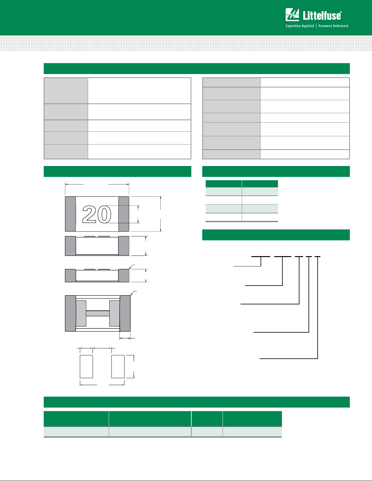
Dimensions
3.200 ± .1778
[.126 ± .007]
1.63 +.10/-.20
1.00
[.064 +.004/-.008]
[.04]
20
0.835 ± 0.15
[.033 ± .006]
Moisture Resistance MIL-STD-202, Method 106G
Thermal Shock
Mechanical Shock
MIL-STD-202, Method 107G,
Condition B
MIL-STD-202, Method 213B,
Condition A
Vibration MIL-STD-202, Method 201A
Vibration,
High Frequency
Dissolution of
Metallization
MIL-STD-202, Method 204D,
Condition D
IPC/ECA/JEDEC J-STD-002C,
Condition D
Terminal Strength IEC 60127-4
Part Marking System
Amp Code Marking Code
010. 10
012. 12
015. 15
020. 20
Part Numbering System
Thin Version
.502 ± .08
[.02 ± .003]
TERMINATION
Series
AMP Code
Quantity
W = 3000 pcs
Packing Code
R = Reel Pack
1.000
[.039]
1.500
[.059]
.520 ± .200
[.020 ± .008]
Thickness Code
1.800
[.071]
3.500
[.138]
Packaging
Packaging Option Packaging Specification Quantity
8mm Tape and Reel EIA-481, IEC 60286, Part 3 3000 WR
S = Thin Version
Packaging Code
Quantity &
© 2013 Littelfuse, Inc.
Specifications are subject to change without notice.
Revised: 12/19/13
 Loading...