

Page 1

2 Mbit / 4 Mbit Firmware Hub
SST49LF002A / SST49LF004A
FEATURES:
• Firmware Hub for Intel® 810, 810E, 820, 840
Chipsets
• 2Mbits or 4Mbits SuperFlash
memory array for code/data storage
– SST49LF002A: 256K x8 (2 Mbit)
– SST49LF004A: 512K x8 (4 Mbit)
• Flexible Erase Capability
– Uniform 4 KByte Sectors
– Uniform 32 KByte overlay blocks for SST49LF002A
– Uniform 64 KByte overlay blocks for SST49LF004A
– Top boot block protection
- 32 KByte for SST49LF002A
- 64 KByte for SST49LF004A
– Chip-Erase for PP Mode
• Single 3.0-3.6V Read and Write Operations
• Superior Reliability
– Endurance:100,000 Cycles (typical)
– Greater than 100 years Data Retention
• Low Power Consumption
– Active Current: 10 mA (typical)
– Standby Current: 10 µA (typical)
• Fast Sector-Erase/Byte-Program Operation
– Sector-Erase Time: 18ms (typical)
– Block-Erase Time: 18ms (typical)
– Chip-Erase Time: 70ms (typical)
– Byte-Program Time: 14µs (typical)
– Chip Rewrite Time:
SST49LF002A: 4 seconds (typical)
SST49LF004A: 8 seconds (typical)
– Single-pulse Program or Erase
– Internal timing generation
Advance Information
• Two Operational Modes
– Firmware Hub Interface (FWH) Mode for
in-system operation
– Parallel Programming (PP) Mode for fast
production programming
• Firmware Hub Hardware Interface Mode
– 5-signal communication interface supporting
byte Read and Write
– 33 MHz clock frequency operation
– WP# and TBL# pins provide hardware write
protect for entire chip and/or top Boot Block
– Block Locking Register for all blocks
– Standard SDP Command Set
– Data# Polling and Toggle Bit for End-of-Write
detection
– 5 GPI pins for system design flexibility
– 4 ID pins for multi-chip selection
• Parallel Programming (PP) Mode
– 11 pin multiplexed address and 8 pin data
I/O interface
– Supports fast In-System or PROM programming
for manufacturing
• CMOS I/O Compatibility
• Packages Available
– 32-Pin PLCC
– 32-Pin TSOP (8mm x 14mm)
1
2
3
4
5
6
7
8
9
10
11
PRODUCT DESCRIPTION
The SST49LF00xA flash memory devices are designed to
be read-compatible to the Intel 82802 Firmware Hub
(FWH) device for PC-BIOS application. It provides protection for the storage and update of code and data in addition
to adding system design flexibility through five general
purpose inputs. Two interface modes are supported by the
SST49LF00xA: Firmware Hub (FWH) Interface Mode for
In-System programming and Parallel Programming (PP)
Mode for fast factory programming of PC-BIOS applications.
The SST49LF00xA flash memory devices are manufactured with SST’s proprietary, high performance
SuperFlash Technology. The split-gate cell design and
thick oxide tunneling injector attain better reliability and
manufacturability compared with alternate approaches.
The SST49LF00xA devices significantly improve performance and reliability, while lowering power consumption.
© 2000 Silicon Storage Technology, Inc.The SST logo and SuperFlash are registered trademarks of Silicon Storage Technology, Inc. MPF is a trademark of Silicon Storage Technology, Inc.
504-2 8/00 Intel is a registered trademark of Intel Corporation. These specifications are subject to change without notice.
The SST49LF00xA devices write (Program or Erase) with
a single 3.0-3.6V power supply. It uses less energy during
Erase and Program than alternative flash memory technologies. The total energy consumed is a function of the
applied voltage, current and time of application. Since for
any given voltage range, the SuperFlash technology uses
less current to program and has a shorter erase time, the
total energy consumed during any Erase or Program
operation is less than alternative flash memory technologies. The SST49LF00xA products provide a maximum
Byte-Program time of 20µsec. The entire memory can be
erased and programmed byte-by-byte typically in 8 seconds, when using status detection features such as
Toggle Bit or Data# Polling to indicate the completion of
Program operation. The SuperFlash technology provides
fixed Erase and Program time, independent of the number
of Erase/Program cycles that have performed. Therefore
1
12
13
14
15
16
Page 2

2 Mbit / 4 Mbit Firmware Hub
SST49LF002A / SST49LF004A
Advance Information
the system software or hardware does not have to be
calibrated or correlated to the cumulated number of
Erase cycles as is necessary with alternative flash
memory technologies, whose Erase and Program time
increase with accumulated Erase/Program cycles.
To protect against inadvertent write, the SST49LF00xA
devices have on-chip hardware and software data (SDP)
protection schemes. It is offered with typical endurance
of 100,000 cycles. Data retention is rated at greater than
100 years.
To meet high density, surface mount requirements, the
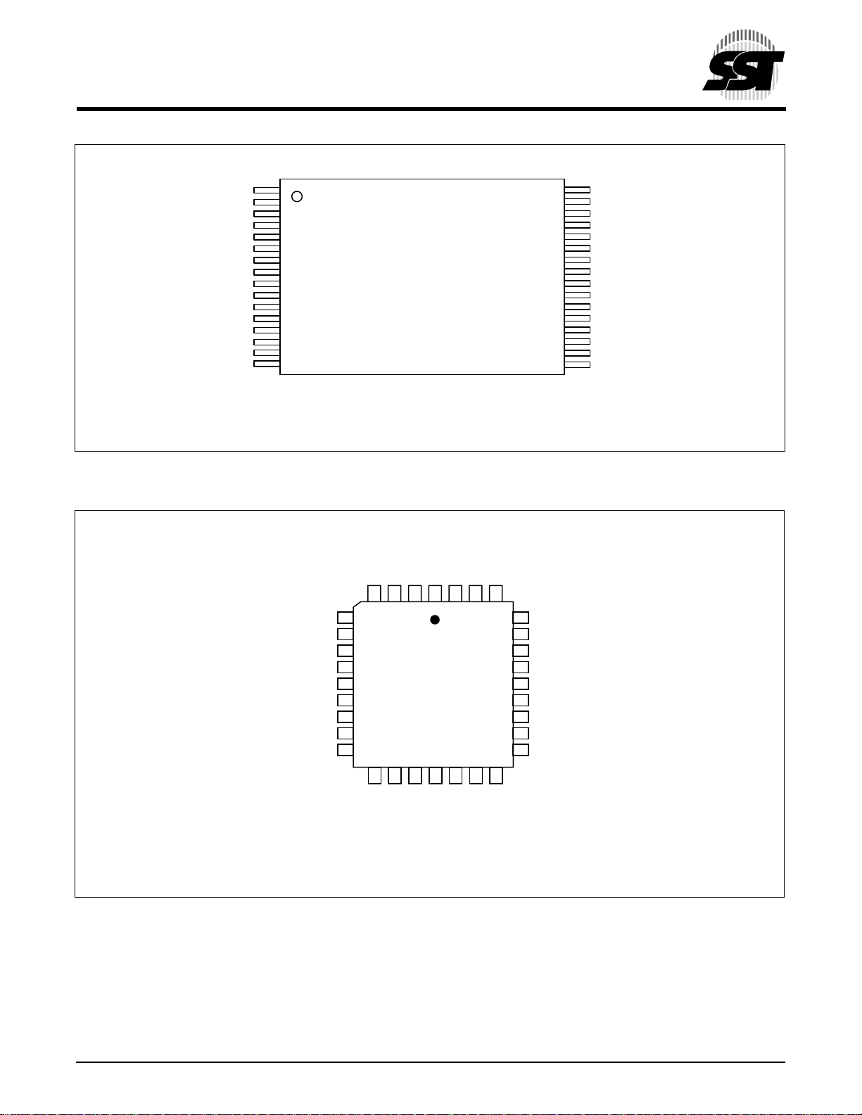
SST49LF00xA device is offered in 32-pin TSOP and 32pin PLCC packages. See Figures 1 and 2 for pinouts and
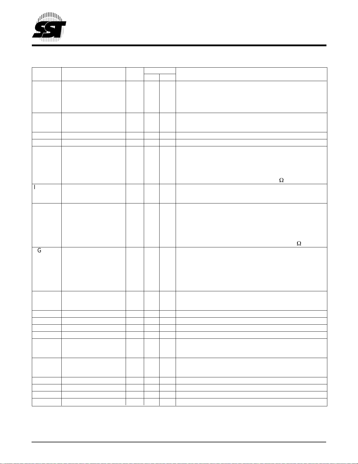
Table 5 for pin descriptions.
Mode Selection and Description
The SST49LF00xA flash memory devices can operate in
two distinct interface modes: the Firmware Hub Interface
(FWH) mode and the Parallel Programming (PP) mode.
The IC (Interface Configuration pin) is used to set the
interface mode selection. If the IC pin is set to logic High,
the device is in PP mode; while if the IC pin is set Low, the
device is in the FWH mode. The IC selection pin must be
configured prior to device operation. In FWH mode, the
device is configured to interface with its host using Intel’s
Firmware Hub proprietary protocol. Communication between Host and the SST49LF00xA occurs via the 4-bit I/
O communication signals, FWH [3:0] and the FWH4. In
PP mode, the device is programmed via an 11-bit address and an 8-bit data I/O parallel signals. The address
inputs are multiplexed in row and column selected by
control signal R/C# pin. The column addresses are
mapped to the higher internal addresses, and the row
addresses are mapped to the lower internal addresses.
See Device Memory Map for address assignments.
FIRMWARE HUB (FWH) MODE
Device Operation
The FWH mode uses a 5-signal communication interface, FWH[3:0] and FWH4, to control operations of the
SST49LF00xA. Operations such as Memory Read and
Memory Write uses Intel FWH propriety protocol.
JEDEC Standard SDP (Software Data Protection) ByteProgram, Sector-Erase and Block-Erase command sequences are incorporated into the FWH memory cycles.
Chip-Erase is only available in PP Mode.
The device enters standby mode when FWH4 is high and
no internal operation is in progress. The device is in
ready mode when FWH4 is low and no activity is on the
FWH bus.
Abort Mechanism
If FWH4 is driven low for one or more clock cycles during
a FWH cycle, the cycle will be terminated and the device
will wait for the ABORT command. The host must drive
the FWH[3:0] with ‘1111b’ (ABORT command) to return
the device to ready mode. If abort occurs during the
internal write cycle, the data may be incorrectly programmed or erased. It is required to wait for the Write
operation to complete prior to initiation of the abort
command. It is recommended to check the write status
with Data# Polling (DQ
) or Toggle Bit (DQ6) pins. One
7
other option is to wait for the fixed write time to expire.
Device Memory Hardware Write Protection
The Top Boot Lock (TBL#) and Write Protect (WP#) pins
are provided for hardware write protection of device
memory in the SST49LF00xA. The TBL# pin is used to
write protect 16 boot sectors (64 KBytes) at the highest
flash memory address range for the SST49LF004A and
8 boot sectors (32 KBytes) for SST49LF002A. WP# pin
write protects the remaining sectors in the flash memory.
An active low signal at the TBL# pin prevents Program
and Erase operations of the top boot sectors. When
TBL# pin is held high, write protection of the top boot
sectors is then determined by the Boot Block Locking
register. The WP# pin serves the same function for the
remaining sectors of the device memory. The TBL# and
WP# pins write protection functions operate independently of one another.
Both TBL# and WP# pins must be set to their required
protection states prior to starting a Program or Erase
operation. A logic level change occurring at the TBL# or
WP# pin during a Program or Erase operation could
cause unpredictable results.
TBL# is internally ORed with the top Boot Block Locking
register. When TBL# is low, the top Boot Block is hardware write protected regardless of the state of the WriteLock bit for the Boot Block Locking register. Clearing the
write protect bit in the register when TBL# is low will have
no functional effect, even though the register may indicate that the block is no longer locked.
WP# is internally ORed with the Block Locking register.
When WP# is low, the blocks are hardware write protected regardless of the state of the Write-Lock bit for the
corresponding Block Locking registers. Clearing the
write protect bit in any register when WP# is low will have
no functional effect, even though the register may indicate that the block is no longer locked.
© 2000 Silicon Storage Technology, Inc. 504-2 8/00
2
Page 3
2 Mbit / 4 Mbit Firmware Hub
SST49LF002A / SST49LF004A
Advance Information
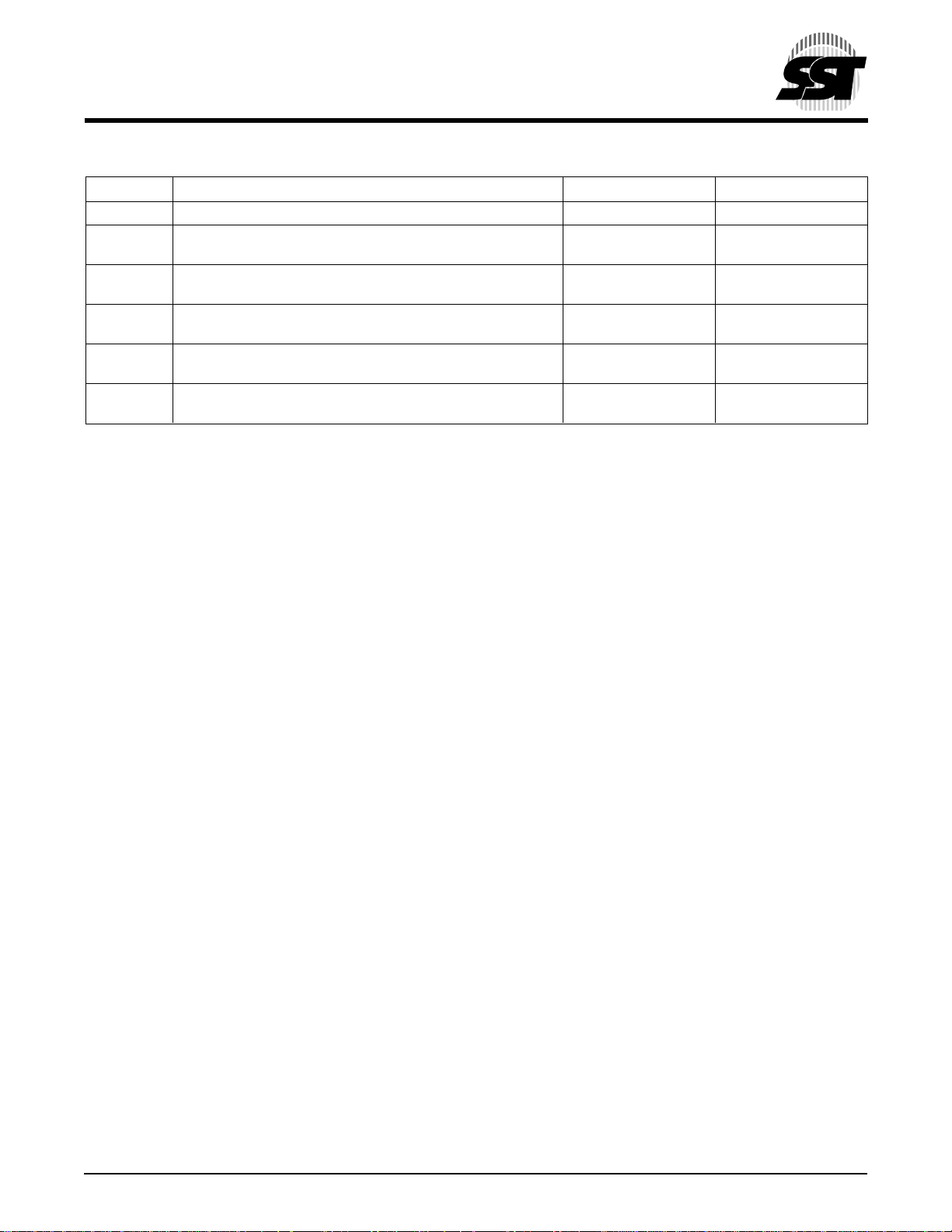
TABLE 1: GENERAL PURPOSE INPUTS REGISTER
Bit Function 32-PLCC Pin# 32-TSOP Pin#
7:5 Reserved - -
4 FGPI[4]
Reads status of general purpose input pin 30 7
3 FGPI[3]
Reads status of general purpose input pin 3 15
2 FGPI[2]
Reads status of general purpose input pin 4 16
1 FGPI[1]
Reads status of general purpose input pin 5 17
0 FGPI[0]
Reads status of general purpose input pin 6 18
Reset
A VIL on INIT# or RST# pin initiates a device reset. INIT#
and RST# pins have the same function internally. It is
required to drive INIT# or RST# pins low during a system
reset to ensure proper CPU initialization.
During a Read operation, driving INIT# or RST# pins low
deselects the device and places the output drivers,
FWH[3:0], in a high-impedance state. The reset signal
must be held low for a minimal duration of time T
reset latency will occur if a reset procedure is performed
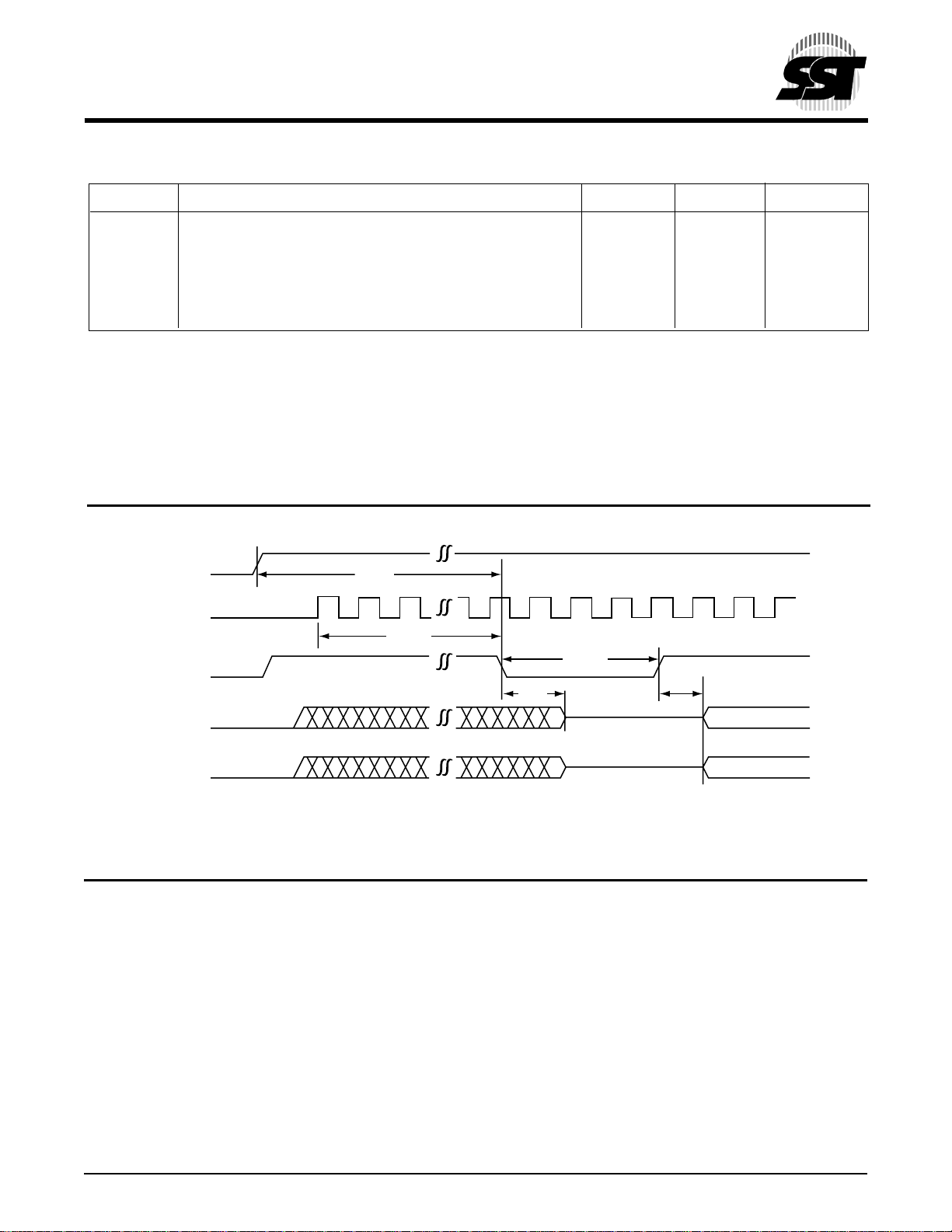
during a Program or Erase operation. See Table 14,
Reset Timing Parameters for more information. A device
reset during an active Program or Erase will abort the
operation and memory contents may become invalid due
to data being altered had been disrupted from an incomplete Erase or Program operation.
Multiple Device Selection
The four ID pins, ID[3:0], allow multiple devices to be
attached to the same bus by using different ID strapping
in a system. When the SST49LF00xA is used as a boot
device, ID[3:0] must be strapped as 0000, all subsequent
devices should use a sequential up-count strapping (i.e.
0001, 0010, 0011, etc.). The SST49LF00xA will compare
the strapping values, if there is a mismatch, the device
will ignore the remainder of the cycle and go into standby
mode. For further information regarding FWH device
mapping and paging, please refer to the Intel 82801(ICH)
I/O Controller Hub documentation. Since there is no ID
support in PP Mode, to program multiple devices a standalone PROM programmer is recommended.
REGISTERS
There are three types of registers available on the
SST49LF00xA, the General Purpose Inputs Register,
Block Locking Registers and the JEDEC ID Registers.
These registers appear at their respective address loca-
RSTP
. A
tion in the 4 GBytes system memory map. Unused
register locations will read as 0x00. Any attempt to read
or write any registers during internal write operation will
be ignored.
General Purpose Inputs Register
The GPI_REG (General Purpose Inputs Register)
passes the state of FGPI[4:0] pins at power-up on the
SST49LF00xA. It is recommended that the FGPI[4:0]
pins are in the desired state before FWH4 is brought low
for the beginning of the bus cycle, and remain in that state
until the end of the cycle. There is no default value since
this is a pass-through register. The GPI register for the
boot device appears at FFBC0100H in the 4 GBytes
system memory map, and will appear elsewhere if the
device is not the boot device. Register is not available for
read when the device is in Erase/Program operation.
Refer to the relevant application note for details. See
Table 1 for the GPI_REG bits and function.
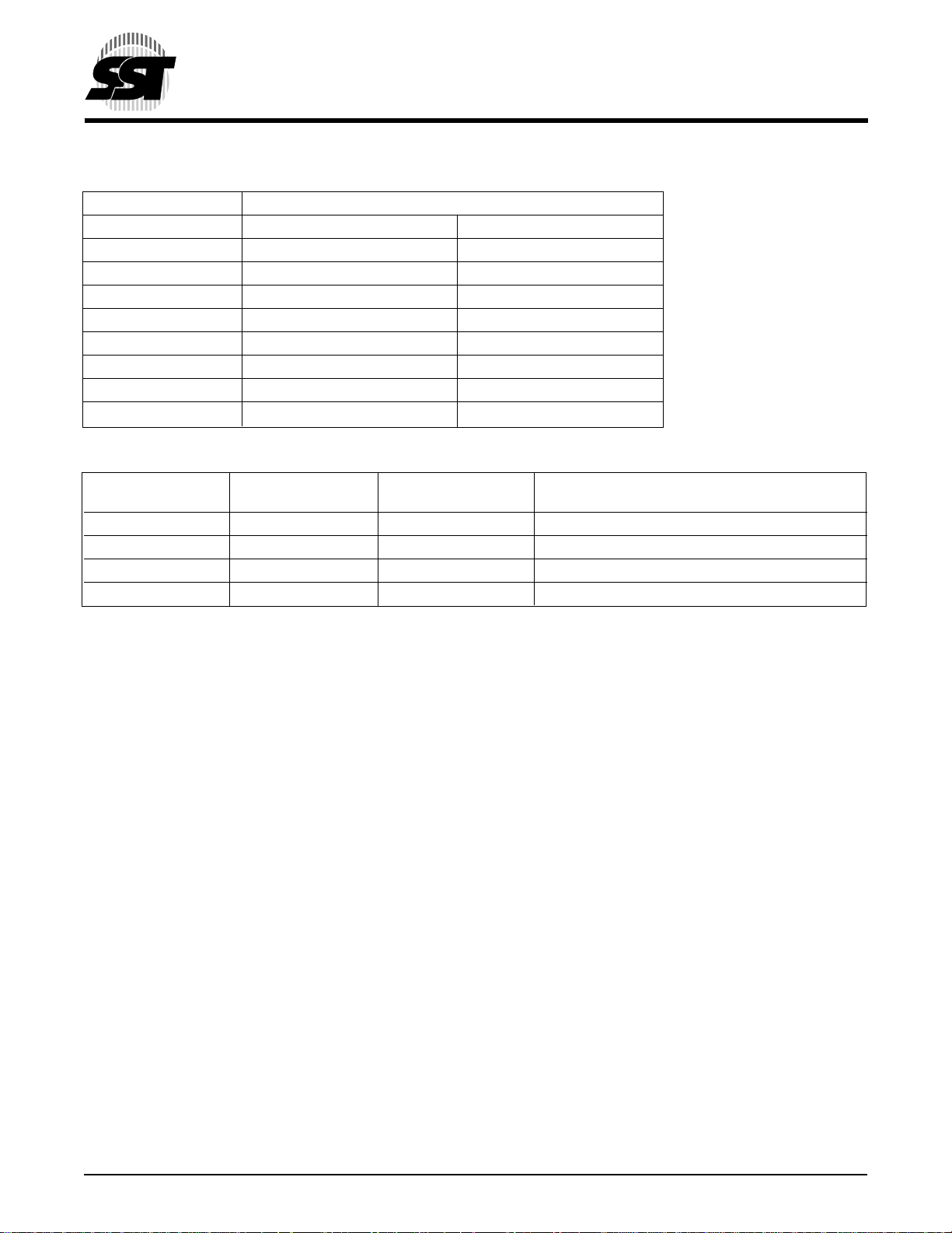
Block Locking Registers
The SST49LF00xA offers software control lock protection through the Block Locking registers. The Block
Locking registers are read/write registers and it is accessible through standard addressable memory locations
listed in Table 2. There are 8 blocks for both the
SST49LF002A and SST49LF004A devices. Each block
has its own Block Locking register.
Write Lock
The Write-Lock bit, bit 0, controls the lock state described
in Table 3. The default write status of all blocks after
power-up is write locked. When bit 0 of the Block Locking
register is set, Program and Erase operations for the
correponding block are prevented. Clearing the WriteLock bit will unprotect the block. The Write-Lock bit must
be cleared prior to starting a Program or Erase operation
since it is sampled at the beginning of the operation.
1
2
3
4
504 PGM T1.1
5
6
7
8
9
10
11
12
13
14
15
16
© 2000 Silicon Storage Technology, Inc. 504-2 8/00
3
Page 4
2 Mbit / 4 Mbit Firmware Hub
SST49LF002A / SST49LF004A
Advance Information
TABLE 2: BLOCK LOCKING REGISTERS
Memory Address
Register SST49LF002A SST49LF004A
Block 7 (Boot Block) FFBF8002H FFBF0002H
Block 6 Register FFBF0002H FFBE0002H
Block 5 Register FFBE8002H FFBD0002H
Block 4 Register FFBE0002H FFBC0002H
Block 3 Register FFBD8002H FFBB0002H
Block 2 Register FFBD0002H FFBA0002H
Block 1 Register FFBC8002H FFB90002H
Block 0 Register FFBC0002H FFB80002H
504 PGM T2.1
TABLE 3: BLOCK LOCKING REGISTER BITS
Reserved Lock-Down Write-Lock Lock Status
Bit [7..2] Bit [1] Bit [0]
000000 0 0 Full Access
000000 0 1 Write Locked (Default State at Power-Up)
000000 1 0 Locked Open (Full Access Locked Down)
000000 1 1 Write Locked Down
504 PGM T3.3
The Write-Lock bit functions in conjunction with the
hardware Write Lock pin TBL# for the top Boot Block.
When TBL# is low, it overrides the software locking
scheme. The top Boot Block Locking register does not
indicate the state of the TBL# pin.
The Write-Lock bit functions in conjunction with the
hardware WP# pin for blocks 0 to 6. When WP# is low,
it overrides the software locking scheme. The Block
Locking register does not indicate the state of the WP#
pin.
Lock Down
The Lock-Down bit, bit 1, controls the Block Locking
register as described in Table 3. When in the FWH
interface mode, the default Lock Down status of all
blocks upon power-up is not locked down. Once the
Lock-Down bit is set, any future attempted changes to
that Block Locking register will be ignored. The LockDown bit is only cleared upon a device reset with RST#
or INIT# or power down. Current Lock Down status of a
particular block can be determined by reading the corresponding Lock-Down bit. Once a block’s Lock-Down bit
is set, the Write-Lock bits for that block can no longer be
modified, and the block is locked down in its current state
of write accessibility.
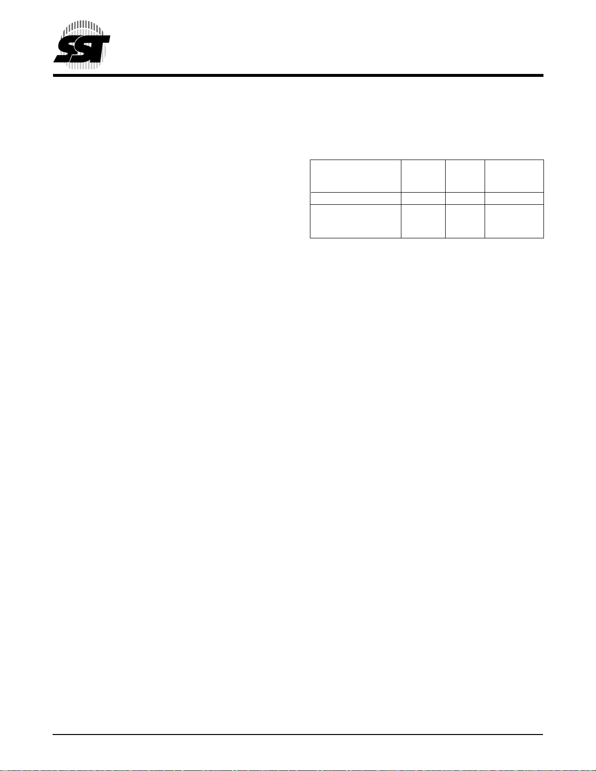
JEDEC ID Registers
The JEDEC ID registers for the boot device appear at
FFBC0000H and FFBC0001H in the 4 GBytes system
memory map, and will appear elsewhere if the device is
not the boot device. Register is not available for read
when the device is in Erase/Program operation. Unused
register location will read as 0x00. Refer to the relevant
application note for details. See Table 4 for device ID
code.
PARALLEL PROGRAMMING MODE
Device Operation
Commands are used to initiate the memory operation
functions of the device. The data portion of the software
command sequence is latched on the rising edge of
WE#. During the software command sequence the row
address is latched on the falling edge of R/C# and the
column address is latched on the rising edge of R/C#.
Read
The Read operation of the SST49LF00xA device is
controlled by OE#. OE# is the output control and is used
to gate data from the output pins. Refer to the Read cycle
timing diagram, Figure 7, for further details.
Reset
A V
on RST# pin initiates a device reset.
IL
© 2000 Silicon Storage Technology, Inc. 504-2 8/00
4
Page 5

2 Mbit / 4 Mbit Firmware Hub
SST49LF002A / SST49LF004A
Advance Information
Byte-Program Operation
The SST49LF00xA device is programmed on a byte-bybyte basis. The Byte-Program operation is initiated by
executing a four-byte-command load sequence for Software Data Protection with address (BA) and data in the
last byte sequence. During the Byte-Program operation,
the row address (A10-A0) is latched on the falling edge
of R/C# and the column Address (A21-A11) is latched on
the rising edge of R/C#. The data bus is latched in the
rising edge of WE#. The Program operation, once initiated, will be completed, within 20 µs. See Figure 8 for
Program operation timing diagram, Figure 11 for timing
waveforms, and Figure 19 for its flowchart. During the
Program operation, the only valid reads are Data# Polling and Toggle Bit. During the internal Program operation, the host is free to perform additional tasks. Any
commands written during the internal Program operation
will be ignored.
Sector-Erase Operation
The Sector-Erase operation allows the system to erase
the device on a sector-by-sector basis. The sector architecture is based on uniform sector size of 4 KByte. The
Sector-Erase operation is initiated by executing a
six-byte-command load sequence for Software Data
Protection with Sector-Erase command (30H) and sector address (SA) in the last bus cycle. The internal Erase
operation begins after the sixth WE# pulse. The End-ofErase can be determined using either Data# Polling or
Toggle Bit methods. See Figure 12 for Sector-Erase
timing waveforms. Any commands written during the
Sector-Erase operation will be ignored.
Block-Erase Operation
The Block-Erase Operation allows the system to erase
the device in 64 KByte uniform block size for the
SST49LF004A and 32 KByte uniform block size for the
SST49LF002A. The Block-Erase operation is initiated
by executing a six-byte-command load sequence for
Software Data Protection with Block-Erase command
(50H) and block address. The internal Block-Erase operation begins after the sixth WE# pulse. The End-ofErase can be determined using either Data# Polling or
Toggle Bit methods. See Figure 13 for timing waveforms.
Any commands written during the Block-Erase operation
will be ignored.
Chip-Erase
The SST49LF00xA device provides a Chip-Erase
operation only in PP Mode, which allows the user to
erase the entire memory array to the “1’s” state. This is
useful when the entire device must be quickly erased.
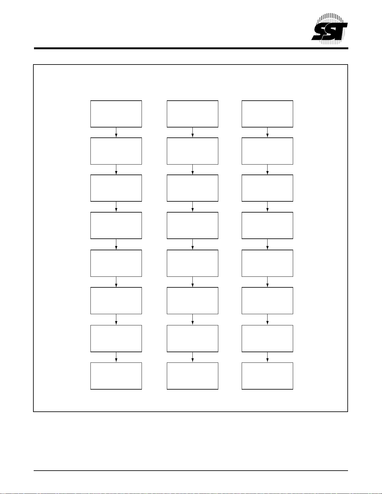
The Chip-Erase operation is initiated by executing a sixbyte Software Data Protection command sequence with
Chip-Erase command (10H) with address 5555H in the
last byte sequence. The internal Erase operation begins
with the rising edge of the sixth WE#. During the internal
Erase operation, the only valid read is Toggle Bit or
Data# Polling. See Table 7 for the command sequence,
Figure 14 for timing diagram, and Figure 22 for the
flowchart. Any commands written during the Chip-Erase
operation will be ignored.
Write Operation Status Detection
The SST49LF00xA device provides two software
means to detect the completion of a Write (Program or
Erase) cycle, in order to optimize the system write cycle
time. The software detection includes two status bits :
Data# Polling (DQ
Write detection mode is enabled after the rising edge of
WE# which initiates the internal Program or Erase operation.
The actual completion of the nonvolatile write is asynchronous with the system; therefore, either a Data#
Polling or Toggle Bit read may be simultaneous with the
completion of the Write cycle. If this occurs, the system
may possibly get an erroneous result, i.e., valid data may
appear to conflict with either DQ7 or DQ6. In order to
prevent spurious rejection, if an erroneous result occurs,
the software routine should include a loop to read the
accessed location an additional two (2) times. If both
reads are valid, then the device has completed the Write
cycle, otherwise the rejection is valid.
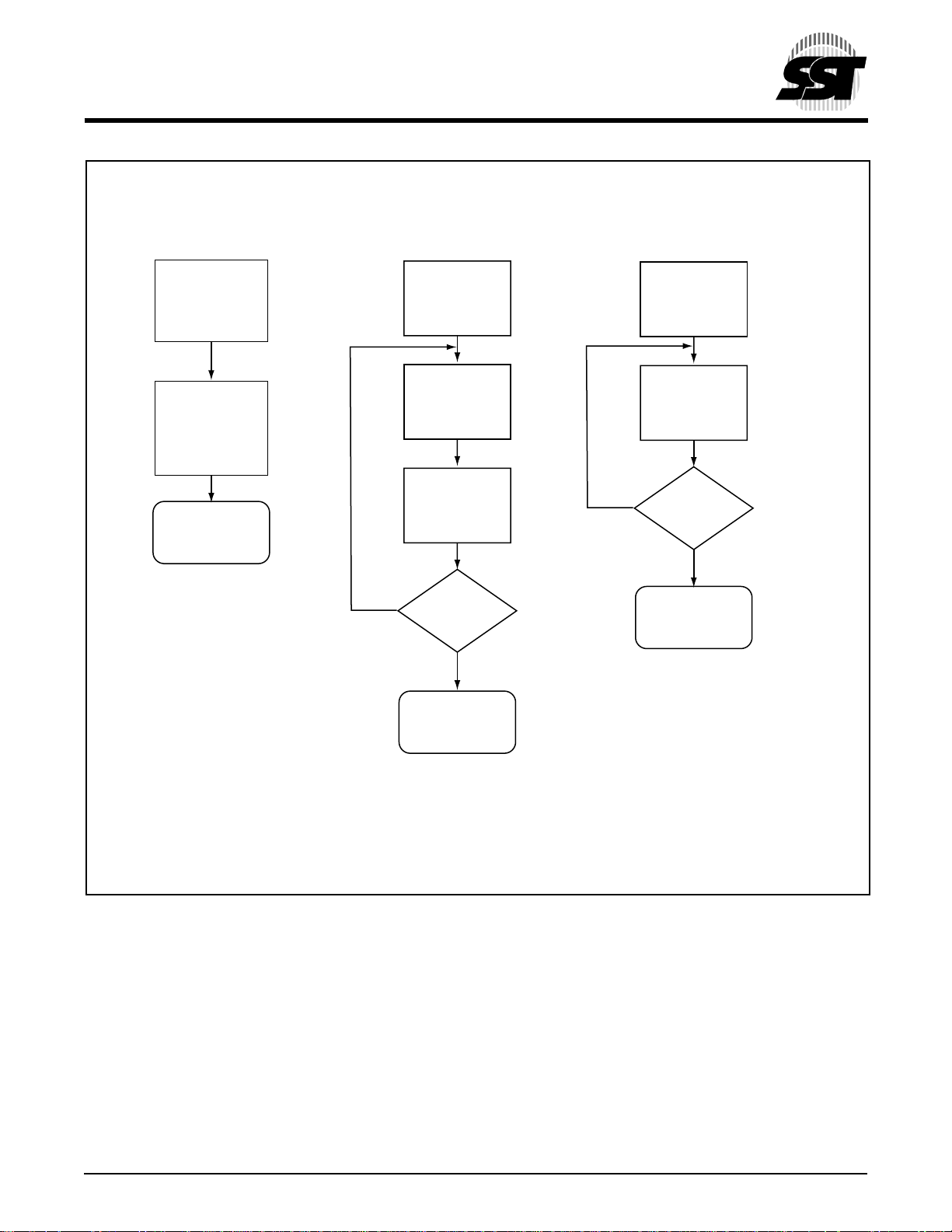
Data# Polling (DQ7)
When the SST49LF00xA device is in the internal Program operation, any attempt to read DQ7 will produce the
complement of the true data. Once the Program operation is completed, DQ7 will produce true data. The device
is then ready for the next operation. During internal
Erase operation, any attempt to read DQ7 will produce
a ‘0’. Once the internal Erase operation is completed,
DQ7 will produce a ‘1’. The Data# Polling is valid after the
rising edge of fourth WE# pulse for Program operation.
For Sector- or Chip-Erase, the Data# Polling is valid after
the rising edge of sixth WE# pulse. See Figure 9 for
Data# Polling timing diagram and Figure 20 for a flowchart.
Toggle Bit (DQ6)
During the internal Program or Erase operation, any
consecutive attempts to read DQ6 will produce alternating 0’s and 1’s, i.e., toggling between 0 and 1. When the
internal Program or Erase operation is completed, the
toggling will stop. The device is then ready for the next
) and Toggle Bit (DQ6). The End-of-
7
1
2
3
4
5
6
7
8
9
10
11
12
13
14
15
16
© 2000 Silicon Storage Technology, Inc. 504-2 8/00
5
Page 6
2 Mbit / 4 Mbit Firmware Hub
SST49LF002A / SST49LF004A
Advance Information
operation. The Toggle Bit is valid after the rising edge of
fourth WE# pulse for Program operation. For Sector-,
Block- or Chip-Erase, the Toggle Bit is valid after the
rising edge of sixth WE# pulse. See Figure 10 for Toggle
Bit timing diagram and Figure 20 for a flowchart.
Data Protection
The SST49LF00xA device provides both hardware and
software features to protect nonvolatile data from inadvertent writes.
Hardware Data Protection
Noise/Glitch Protection: A WE# pulse of less than 5 ns
will not initiate a Write cycle.
VDD Power Up/Down Detection: The Write operation is
inhibited when VDD is less than 1.5V.
Write Inhibit Mode: Forcing OE# low, WE# high will inhibit
the Write operation. This prevents inadvertent writes
during power-up or power-down.
Software Data Protection (SDP)
The SST49LF00xA provides the JEDEC approved Software Data Protection scheme for all data alteration
operation, i.e., program and erase. Any Program operation requires the inclusion of a series of three byte
sequence. The three byte-load sequence is used to
initiate the Program operation, providing optimal protection from inadvertent Write operations, e.g., during the
system power-up or power-down. Any Erase operation
requires the inclusion of six byte load sequence. The
SST49LF00xA device is shipped with the Software Data
Protection permanently enabled. See Table 7 for the
specific software command codes. During SDP command sequence, invalid commands will abort the device
to read mode, within TRC.
Product Identification Mode
The product identification mode identifies the device as
the SST49LF00xA and manufacturer as SST.
TABLE 4: PRODUCT IDENTIFICATION TABLE
JEDEC ID
Address
Byte Data Location
Manufacturer’s ID 0000 H BF H FFBC0000H
Device ID
SST49LF002A 0001 H 57H FFBC0001H
SST49LF004A 0001 H 60H FFBC0001H
504 PGM T4.3
Design Considerations
SST recommends a high frequency 0.1 µF ceramic
capacitor to be placed as close as possible between V
and V
less than 1 cm away from the VDD pin of the
SS
DD
device. Additionally, a low frequency 4.7 µF electrolytic
capacitor from VDD to VSS should be placed within 1 cm
of the VDD pin. If you use a socket for programming
purposes add an additional 1-10 µF next to each socket.
The RST# pin must remain stable at VIH for the entire
duration of an Erase operation. WP# must remain stable
at VIH for the entire duration of the Erase and Program
operations for non-boot block sectors. To write data to
the top boot block sectors, the TBL# pin must also remain
stable at VIH for the entire duration of the Erase and
Program operations.
Electrical Specifications
The AC and DC specifications for the FWH Interface
signals (FWH[3:0], CLK, FWH4, and RST#) as defined in
Section 4.2.2 of the “PCI Local Bus Specification, Rev.
2.1”. Refer to Table 8 for the DC voltage and current
specifications. Refer to Tables 13, 14, 16 and 17 for the
AC timing specifications for Clock, Read, Program,
Erase and Reset operations.
© 2000 Silicon Storage Technology, Inc. 504-2 8/00
6
Page 7
2 Mbit / 4 Mbit Firmware Hub
SST49LF002A / SST49LF004A
Advance Information
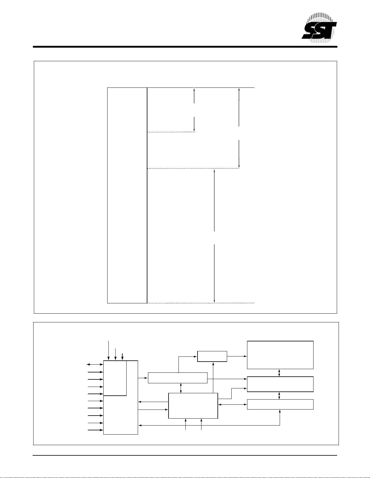
BOOT-CONFIGURATION SYSTEM MEMORY MAP
System Memory
(Top 4 MByte)
FFFFFFFFH
1
FFFC0000H
FFF80000H
FFF00000H
SST49LF002A
(2 Mbit)
3.5 MBytes for
Additional FWH Devices
SST49LF004A
(4 Mbit)
2
3
4
5
6
7
8
9
FFC00000H
504 ILL B1A.1
FUNCTIONAL BLOCK DIAGRAM
TBL#
WP#
INIT#
X-Decoder
FWH[3:0]
CLK
FWH4
ID[3:0]
FGPI[4:0]
R/C#
A[10:0]
DQ[7:0]
OE#
WE#
© 2000 Silicon Storage Technology, Inc. 504-2 8/00
FWH
Interface
Programmer
Interface
Address Buffers & Latches
Control Logic
IC
RST#
7
SuperFlash
Cell Array
Y-Decoder
I/O Buffers and Data Latches
504 ILL B1.1
10
11
12
13
14
15
16
Page 8
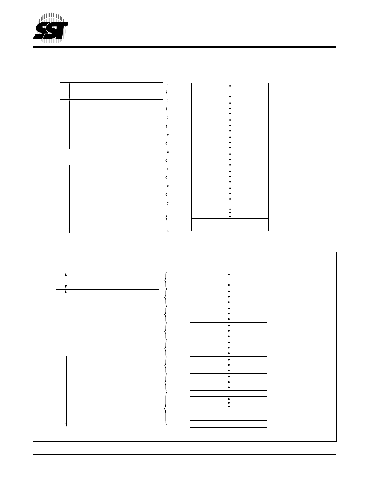
DEVICE MEMORY MAP FOR SST49LF002A
2 Mbit / 4 Mbit Firmware Hub
SST49LF002A / SST49LF004A
Advance Information
TBL#
WP# for
Block 0~6
D
EVICE MEMORY MAP FOR SST49LF004A
Block 7
Block 6
Block 5
Block 4
Block 3
Block 2
Block 1
Block 0
(32 KByte)
3FFFFH
38000H
37FFFH
30000H
2FFFFH
28000H
27FFFH
20000H
1FFFFH
18000H
17FFFH
10000H
0FFFFH
08000H
07FFFH
01000H
00000H
Boot Block
4 KByte Sector 7
4 KByte Sector 1
4 KByte Sector 0
504 ILL F52.3
TBL#
WP# for
Block 0~6
Block 7
Block 6
Block 5
Block 4
Block 3
Block 2
Block 1
Block 0
(64 KByte)
7FFFFH
70000H
6FFFFH
60000H
5FFFFH
50000H
4FFFFH
40000H
3FFFFH
30000H
2FFFFH
20000H
1FFFFH
10000H
0F000H
02000H
01000H
00000H
Boot Block
4 KByte Sector 15
4 KByte Sector 2
4 KByte Sector 1
4 KByte Sector 0
504 ILL F45.4
© 2000 Silicon Storage Technology, Inc. 504-2 8/00
8
Page 9
2 Mbit / 4 Mbit Firmware Hub
SST49LF002A / SST49LF004A
Advance Information
NC
NC
NC
V
SS (VSS
IC (IC)
A10 (FGPI4)
R/C# (CLK)
V
DD (VDD
NC
RST# (RST#)
A9 (FGPI3)
A8 (FGPI2)
A7 (FGPI1)
A6 (FGPI0)
A5 (WP#)
A4 (TBL#)
1
2
3
)
4
5
6
7
)
8
9
10
11
12
13
14
15
16
( ) Designates FWH Mode
Standard Pinout
T op Vie w
Die Up
FIGURE 1: PIN ASSIGNMENTS FOR 32-PIN TSOP (8mm x 14mm)
A8 (FGPI2)
A9 (FGPI3)
RST# (RST#)NCV
)
DD
(V
DD
R/C# (CLK)
A10 (FGPI4)
32
31
30
29
28
27
26
25
24
23
22
21
20
19
18
17
OE# (INIT#)
WE# (FWH4)
V
DD (VDD
DQ7 (RES)
DQ6 (RES)
DQ5 (RES)
DQ4 (RES)
DQ3 (LAD3)
V
SS (VSS
DQ2 (LAD2)
DQ1 (LAD1)
DQ0 (LAD0)
A0 (ID0)
A1 (ID1)
A2 (ID2)
A3 (ID3)
504 ILL F01.3
1
)
2
)
3
4
5
6
7
8
A7(FGPI1)
A6 (FGPI0)
A5 (WP#)
A4 (TBL#)
A3 (ID3)
A2 (ID2)
A1 (ID1)
A0 (ID0)
DQ0 (FWH0)
( ) Designates FWH Mode
FIGURE 2: PIN ASSIGNMENTS FOR 32-PIN PLCC
4 3 2 1 32 31 30
5
6
7
8
32-Lead PLCC
9
10
11
12
13
T op Vie w
14 15 16 17 18 19 20
)
SS
(V
SS
V
DQ1 (FWH1)
DQ2 (FWH2)
DQ4 (RES)
DQ3 (FWH3)
29
28
27
26
25
24
23
22
21
DQ5 (RES)
DQ6 (RES)
IC (IC)
VSS (VSS)
NC
NC
V
OE# (INIT#)
WE# (FWH4)
NC
DQ7 (RES)
DD (VDD
504 ILL F02.2
)
9
10
11
12
13
14
15
16
© 2000 Silicon Storage Technology, Inc. 504-2 8/00
9
Page 10
2 Mbit / 4 Mbit Firmware Hub
SST49LF002A / SST49LF004A
Advance Information
TABLE 5: PIN DESCRIPTION
Interface
Symbol Pin Name Type
A10-A
Address I X Inputs for low-order addresses during Read and Write
0
DQ7-DQ0Data I/O X To output data during Read cycles and receive input data
OE# Output Enable I X To gate the data output buffers.
WE# Write Enable I X To control the Write operations.
IC Interface I X X This pin determines which interface is operational. When
Configuration Pin held high, programmer mode is enabled and when held
INIT# Initialize I X This is the second reset pin for in-system use. This pin is
ID[3:0] Identification I X These four pins are part of the mechanism that allows
Inputs multiple parts to be attached to the same bus. The
FGPI[4:0] General I X These individual inputs can be used for additional board
Purpose Inputs flexibility. The state of these pins can be read through
TBL# Top Block Lock I X When low, prevents programming to the boot block
FWH[3:0] FWH I/Os I/O X I/O Communications
CLK Clock I X To provide a clock input to the control unit
FWH4 FWH Input I X Input Communications
RST# Reset I X X To reset the operation of the device
WP# Write Protect I X When low, prevents programming to all
R/C# Row/Column Select I X Select For the Programming interface, this pin determines
RES Reserved X Not implemented. Reserved for future use.
V
DD
Power Supply I X X To provide power supply (3.0-3.6V)
Vss Ground I X X Circuit ground (OV reference)
NC No Connection I X X Unconnected pins.
Note 1. I = Input, O = Output
1
PP FWH Functions
operations. Addresses are internally latched during a
Write cycle. For the programming interface, these
addresses are latched by R/C# and share the same pins
as the high-order address inputs.
during Write cycles. Data is internally latched during a
Write cycle. The outputs are in tri-state when OE# is high.
low, FWH mode is enabled. This pin must be setup at
power-up or before return from reset and not change
during device operation. This pin is internally pulleddown with a resistor between 20-100 K
internally combined with the RST# pin; If this pin or RST#
pin is driven low, identical operation is exhibited.
strapping of these pins is used to identify the component.
The boot device must have ID[3:0] = 0000 and it is
recommended that all subsequent devices should use
sequential up-count strapping. These pins are internally
pulled-down with a resistor between 20-100 K
GPI_REG register. These inputs should be at their
desired state before the start of the PCI clock cycle
during which the read is attempted, and should remain
in place until the end of the Read cycle. Unused GPI pins
must not be floated.
sectors at top of memory. When TBL# is high it disables
hardware write protection for the top block sectors.
but the highest addressable blocks. When WP# is high
it disables hardware write protection for these blocks.
whether the address pins are pointing to the row
addresses, or to the column addresses.
W
W
504 PGM T5.1
© 2000 Silicon Storage Technology, Inc. 504-2 8/00
10
Page 11
2 Mbit / 4 Mbit Firmware Hub
SST49LF002A / SST49LF004A
Advance Information
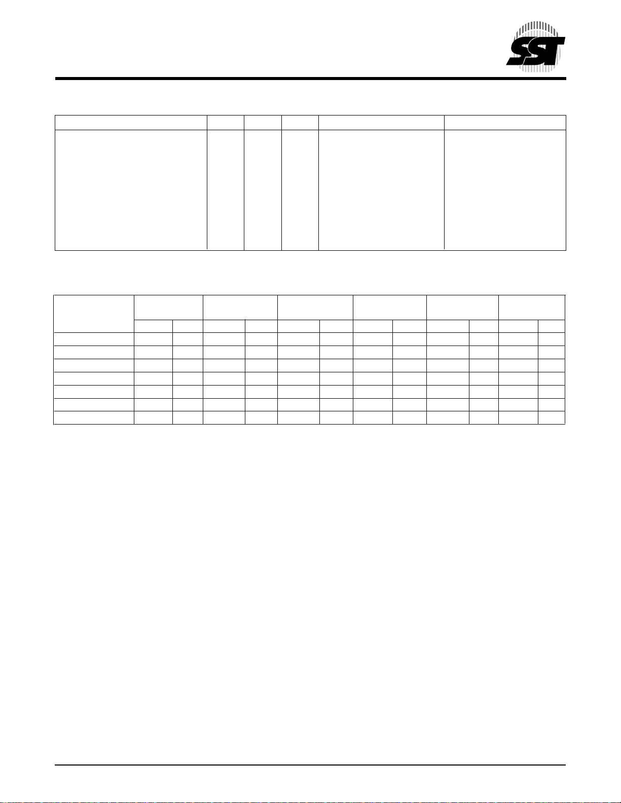
TABLE 6: OPERATION MODES SELECTION (PP MODE)
Mode RST# OE# WE# DQ Address
Read V
Program V
Erase V
Reset V
Write Inhibit V
Product Identification V
IH
IH
IH
IL
IH
XV
IH
V
V
V
V
IL
IH
IH
IH
V
IL
V
IL
D
OUT
D
IN
X Sector or Block address,
X X High Z X
V
IL
IH
V
IL
X High Z/D
High Z/D
V
IH
Manufacturer ID (BF) A18 - A1 = VIL, A0 = V
Device ID
OUT
OUT
(7)
A
IN
A
IN
XXh for Chip-Erase
X
X
A18 - A1 = VIL, A0 = V
IL
IH
504 PGM T6.2
1
2
3
4
TABLE 7: SOFTWARE COMMAND SEQUENCE
Command 1st
(6)
Sequence Write Cycle Write Cycle Write Cycle Write Cycle Write Cycle Write Cycle
(1)
Addr
Data Addr
Byte-Program 5555H AAH 2AAAH 55H 5555H A0H BA
Sector-Erase 5555H AAH 2AAAH 55H 5555H 80H 5555H AAH 2AAAH 55H SA
Block-Erase 5555H AAH 2AAAH 55H 5555H 80H 5555H AAH 2AAAH 55H BA
Chip-Erase
Software ID Entry
(9)
5555H AAH 2AAAH 55H 5555H 80H 5555H AAH 2AAAH 55H 5555H 10H
(7,8)
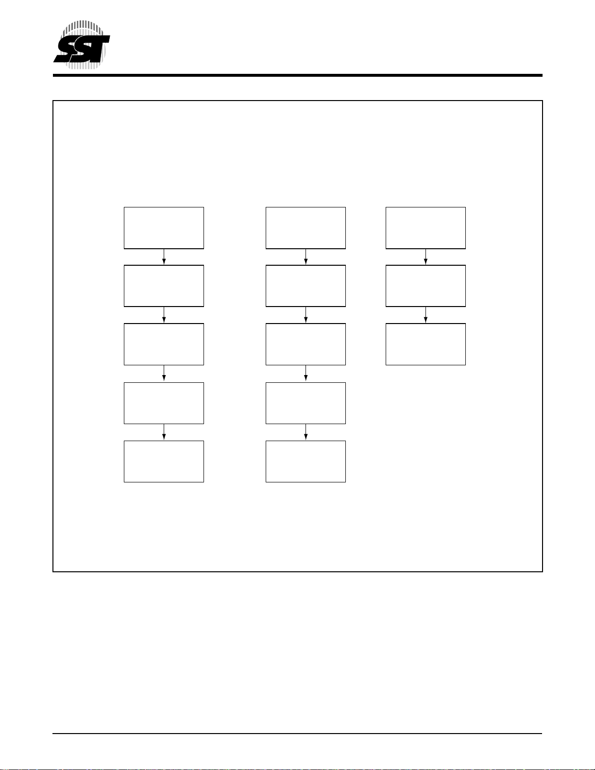
5555H AAH 2AAAH 55H 5555H 90H
Software ID Exit XXH F0H
Software ID Exit 5555H AAH 2AAAH 55H 5555H F0H
Notes:
(1)
Address format A14-A0 (Hex), Addresses A
Command sequence.
(2)
SAx for Sector-Erase Address
(3)
BA = Program Byte address
(4)
Both Software ID Exit operations are equivalent
(5)
BAx for Block-Erase Address
(6)
FWH Mode use consecutive Write cycles to complete a command sequence;
PP Mode use consecutive bus cycles to complete a command sequence.
(7)
SST Manufacturer ID = BFH, is read with A0 = 0,
With A
With A
(8)
The device does not remain in Software Product ID Mode if powered down.
(9)
Chip-Erase is supported in PP Mode only
= 0; 49LF002A Device ID = 57H, is read with A0 = 1.
17 -A1
= 0; 49LF004A Device ID = 60H, is read with A0 = 1.
18 -A1
(6)
2nd
(1)
Data Addr
are a “Don’t Care” for the
15-A21
(6)
3rd
(1)
Data Addr
(3)
4th
(1)
(6)
Data Addr
Data
(6)
5th
(1)
Data Addr
(6)
6th
(1)
(2)
x
(5)
x
504 PGM T7.1
Data
30H
50H
5
6
7
8
9
10
11
12
© 2000 Silicon Storage Technology, Inc. 504-2 8/00
11
13
14
15
16
Page 12
2 Mbit / 4 Mbit Firmware Hub
SST49LF002A / SST49LF004A
Advance Information
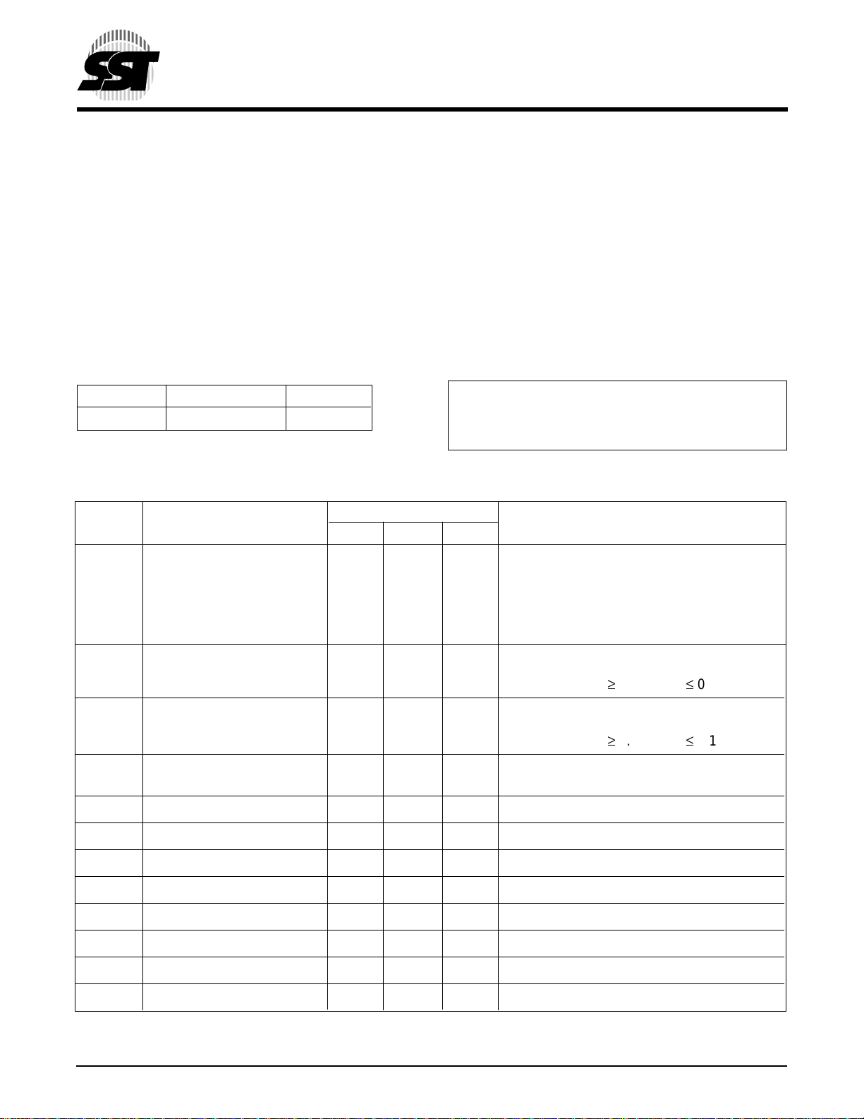
Absolute Maximum Stress Ratings (Applied conditions greater than those listed under “Absolute Maximum Stress
Ratings” may cause permanent damage to the device. This is a stress rating only and functional operation of the device
at these conditions or conditions greater than those defined in the operational sections of this data sheet is not implied.
Exposure to absolute maximum stress rating conditions may affect device reliability.)
Temperature Under Bias ................................................................................................................. -55°C to +125°C
Storage Temperature ...................................................................................................................... -65°C to +150°C
D. C. Voltage on Any Pin to Ground Potential ............................................................................. -0.5V to VDD+ 0.5V
Transient Voltage (<20 ns) on Any Pin to Ground Potential......................................................... -1.0V to VDD+ 1.0V
Package Power Dissipation Capability (TA = 25°C) ...........................................................................................1.0W
Surface Mount Lead Soldering Temperature (3 Seconds)............................................................................... 240°C
Output Short Circuit Current
(1)
Note:
Outputs shorted for no more than one second. No more than one output shorted at a time.
(1)
.................................................................................................................................................................
50 mA
OPERATING RANGE
Range Ambient Temp V
DD
Commercial 0°C to +85°C 3.0-3.6V
AC CONDITIONS OF TEST
Input Rise/Fall Time......... 3 ns
Output Load..................... CL = 30 pF
See Figures 17 and 18
T
ABLE 8: DC OPERATING CHARACTERISTICS (ALL INTERFACE)
Limits
Symbol Parameter Min Max Units Test Conditions
I
DD
Power Supply Current
Read 12 mA OE# = VIL, WE# = VIH, All I/Os open,
Address input = VIL/VIH, at F = 1/TRC Min.,
VDD = VDD Max
Write 15 mA OE#=VIL, WE#=VIL, VDD = VDD Max
I
SB
Standby V
Current 100 µA FWH4 = 0.9VDD, f = 33 MHz
DD
(FWH Interface) VDD = VDD Max,
All other inputs ³ 0.9 V
(1)
I
RY
Ready Mode V
Current 10 mA FWH4 = VIL, f = 33 MHz
DD
(FWH Interface) VDD = VDD Max
All other inputs ³ 0.9 V
I
I
Input Current for IC, 2 00 µA V
= GND to VDD, VDD = VDD Max
IN
ID [3:0] pins
or £ 0.1 V
DD
or £ 0.1 V
DD
DD
DD
I
LI
I
LO
V
IHI
V
ILI
V
IL
V
IH
V
OL
V
OH
Note: (1) The device is in Ready Mode when no activity is on the FWH bus.
© 2000 Silicon Storage Technology, Inc. 504-2 8/00
Input Leakage Current 1 µA V
Output Leakage Current 1 µA V
= GND to VDD, VDD = VDD Max
IN
= GND to VDD, VDD = VDD Max
OUT
INIT# Input High Voltage 1.0 VDD+0.5 V VDD = VDD Max
INIT# Input Low Voltage -0.5 0.4 V VDD = VDD Max
Input Low Voltage -0.5 0.3 V
DD
VVDD = VDD Min
Input High Voltage 0.5 VDDVDD+0.5 V VDD = VDD Max
Output Low Voltage 0.1 V
Output High Voltage 0.9 V
DD
DD
VIOL = 1500µA, VDD = VDD Min
VIOH = -500 µA, VDD = VDD Min
12
504 PGM T8.3
Page 13
2 Mbit / 4 Mbit Firmware Hub
SST49LF002A / SST49LF004A
Advance Information
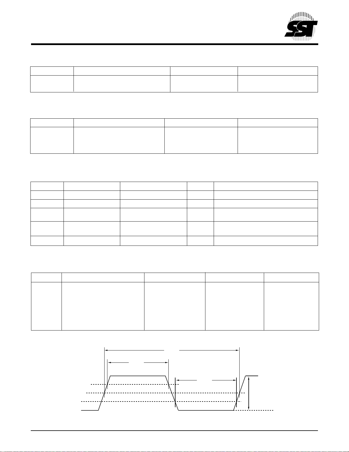
TABLE 9: RECOMMENDED SYSTEM POWER-UP TIMINGS
Symbol Parameter Minimum Units
T
PU-READ
T
PU-WRITE
Note: (1) This parameter is measured only for initial qualification and after a design or process change that could
affect this parameter.
TABLE 10: PIN IMPEDANCE (VDD = 3.3V, Ta = 25 °C, f=1 Mhz, other pins open)
Parameter Description Test Condition Maximum
C
I/O
C
IN
L
PIN
Note: (2) This parameter is measured only for initial qualification and after a design or process change that could affect this parameter.
TABLE 11: RELIABILITY CHARACTERISTICS
Symbol Parameter Minimum Specification Units Test Method
N
END
(4)
T
DR
V
ZAP_HBM
V
ZAP_MM
(4)
I
LTH
Note: (4) This parameter is measured only for initial qualification and after a design or process change that could affect this parameter.
(1)
(1)
(2)
(2)
(3)
(3) Refer to PCI spec.
(4)
Power-up to Read Operation 100 µs
Power-up to Write Operation 100 µs
I/O Pin Capacitance V
Input Capacitance V
Pin Inductance 20 nH
Endurance 10,000 Cycles JEDEC Standard A117
Data Retention 100 Years JEDEC Standard A103
(4)
ESD Susceptibility 2000 Volts JEDEC Standard A114
Human Body Model
(4)
ESD Susceptibility 200 Volts JEDEC Standard A115
Machine Model
Latch Up 100 + I
DD
= 0V 12 pF
I/O
= 0V 12 pF
IN
mA JEDEC Standard 78
504 PGM T9.2
504 PGM T10.3
504 PGM T11.2
1
2
3
4
5
6
7
8
9
TABLE 12: CLOCK TIMING PARAMETERS
Symbol Parameter Min Max Units
T
T
T
CYC
HIGH
LOW
CLK Cycle Time 30 ns
CLK High Time 11 ns
CLK Low Time 11 ns
– CLK Slew Rate 1 4 V/ns
(peak-to-peak)
– RST# or INIT# Slew Rate 50 mV/ns
504 PGM T12.1
T
cyc
T
high
0.6 V
0.4 V
0.3 V
0.5 V
DD
DD
DD
DD
T
low
0.2 V
DD
0.4 V
DD
(minimum)
504 ILL F27.0
p-to-p
FIGURE 3: CLK WAVEFORM
© 2000 Silicon Storage Technology, Inc. 504-2 8/00
13
10
11
12
13
14
15
16
Page 14
2 Mbit / 4 Mbit Firmware Hub
SST49LF002A / SST49LF004A
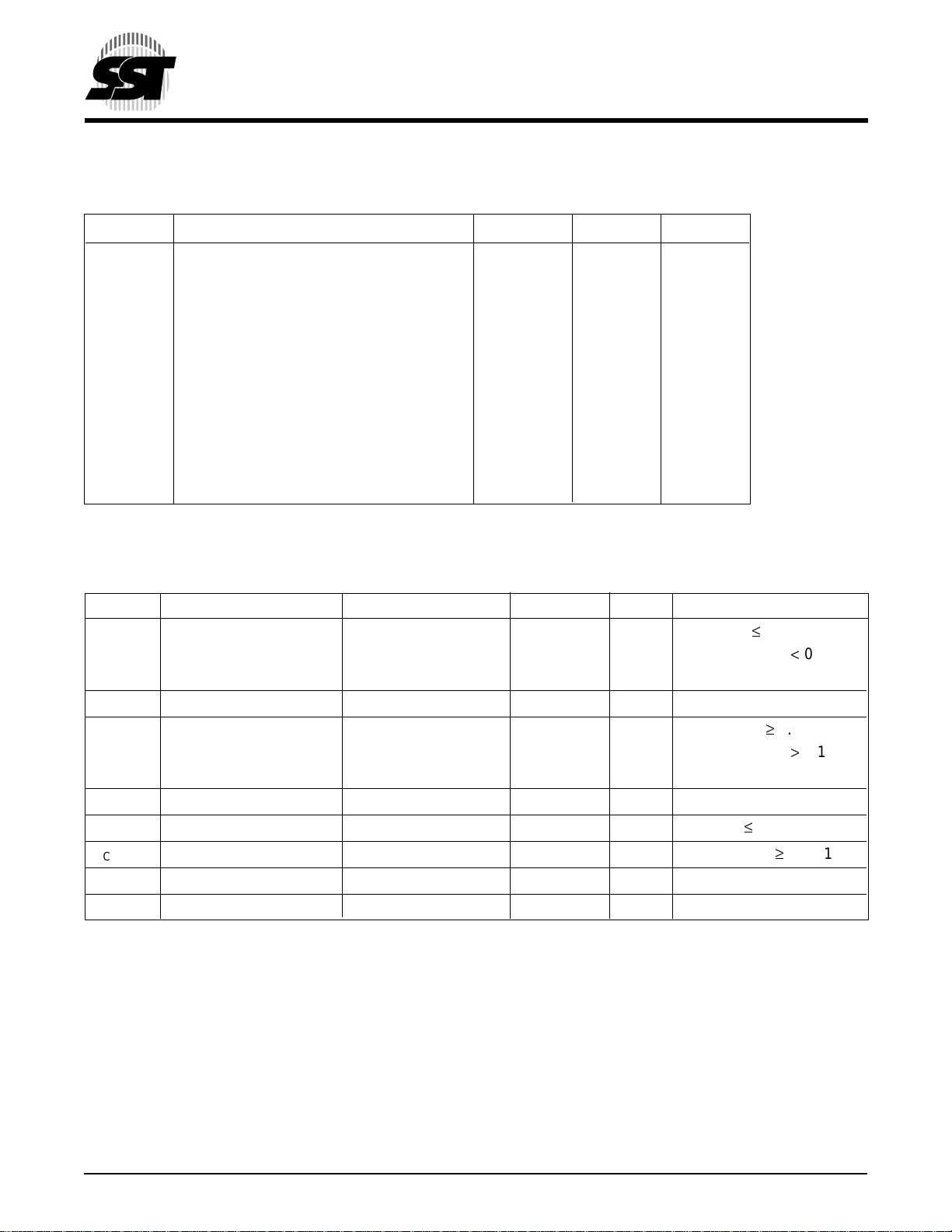
AC CHARACTERISTICS (FWH MODE)
T
ABLE 13: READ/WRITE CYCLE TIMING PARAMETERS (FWH MODE), V
Symbol Parameter Min Max Units
= 3.0-3.6V
DD
Advance Information
T
T
T
T
T
T
T
T
T
CYC
SU
DH
VAL
BP
SE
BE
SCE
ON
(1)
Clock Cycle Time 30 ns
Data Set Up Time to Clock Rising 7 ns
Clock Rising to Data Hold Time 0 ns
Clock Rising to Data Valid 2 11 ns
Byte Programming Time 20 µs
Sector-Erase Time 25 ms
Block-Erase Time 25 ms
Chip-Erase Time 100 ms
Clock Rising to Active 2 ns
(Float to Active Delay)
T
OFF
Clock Rising to Inactive 28 ns
(Active to Float Delay)
Note: (1) Minimum and maximum times have different loads. See PCI spec.
504 PGM T13.3
TABLE 13A: AC INPUT/OUTPUT SPECIFICATIONS (FWH MODE)
Symbol Parameter Min Max Units Conditions
IOH(AC) Switching Current High -12V
-17.1(VDD-V
(Test Point) -32V
IOL(AC) Switching Current Low 16V
-17.1(VDD-V
(Test Point) 38V
I
CL
I
CH
slewr
slewf
Note: (2) PCI specification output load is used.
(3) See PCI spec.
Low Clamp Current -25+(VIN+1)/0.015 mA -3 < VIN £ -1
High Clamp Current 25+(VIN-VDD-1)/0.015 mA VDD+4 > VIN ³ VDD+1
(2)
Output Rise Slew Rate 1 4 V/ns 0.2VDD-0.6V
(2)
Output Fall Slew Rate 1 4 V/ns 0.6VDD-0.2V
DD
DD
) mA 0.3VDD < V
OUT
Equation C
DD
) mA 0.6VDD > V
OUT
Equation D
DD
mA 0 < V
(3)
mA V
mA VDD >V
(3)
mA V
0.7V
OUT
0.18V
OUT
OUT
DD
= 0.7V
= 0.18V
< V
OUT
DD
£ 0.3V
OUT
OUT
DD
³ 0.6V
OUT
> V
OUT
DD
DD
DD
DD
< 0.9V
<V
> 0.1V
DD
DD
DD
DD
> 0
load
load
504 PGM T13A.1
© 2000 Silicon Storage Technology, Inc. 504-2 8/00
14
Page 15
2 Mbit / 4 Mbit Firmware Hub
SST49LF002A / SST49LF004A
Advance Information
TABLE 14: RESET TIMING PARAMETERS, VDD = 3.0-3.6V
Symbol Parameter Min Max Units
T
T
T
T
T
PRST
KRST
RSTP
RSTF
RST
VDD stable to Reset Active 1 ms
Clock Stable to Reset Active 100 µs
Reset Pulse Width 100 ns
Reset Active to Output Float 50 ns
Reset Inactive to Input Active 10 µs
504 PGM T14.2
1
2
3
4
5
6
V
DD
CLK
RST#/INIT#
FWH[3:0]
FWH4
FIGURE 4: RESET TIMING DIAGRAM
T
PRST
T
KRST
T
RSTF
T
RSTP
T
RST
504 ILL F51.0
7
8
9
10
11
12
13
14
© 2000 Silicon Storage Technology, Inc. 504-2 8/00
15
15
16
Page 16
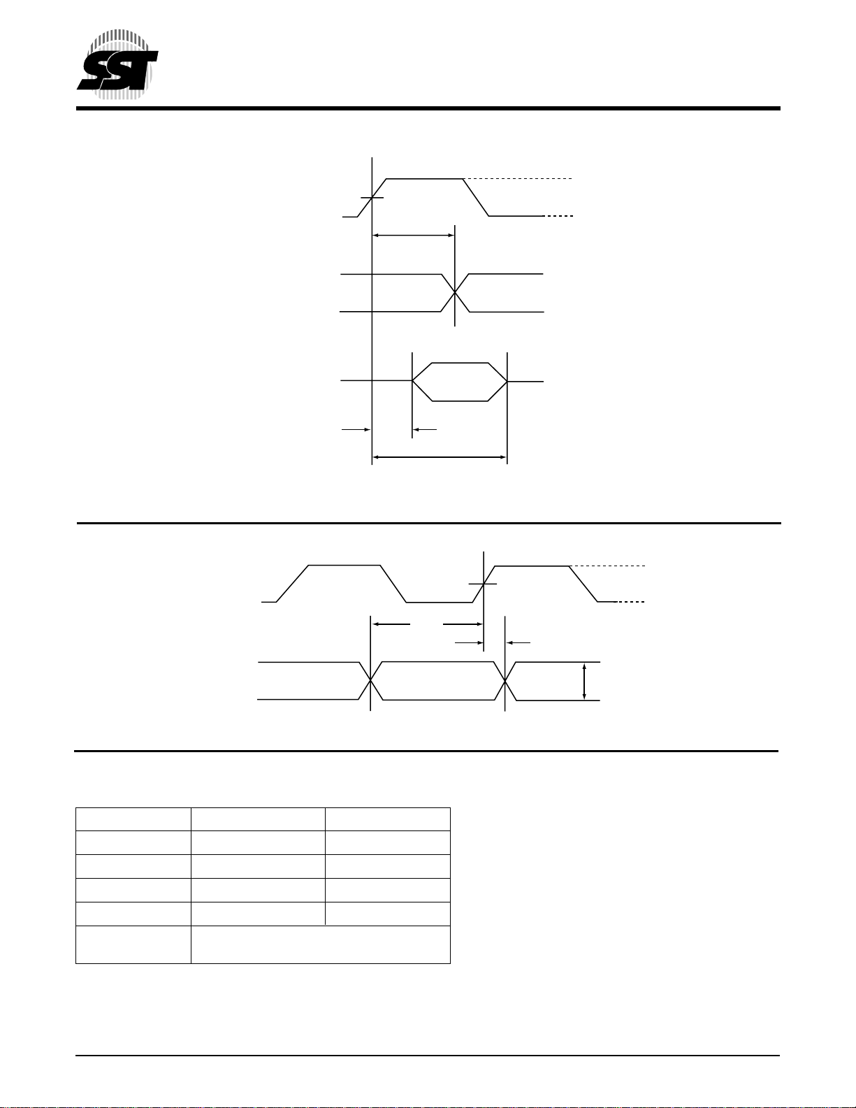
CLK
FWH [3:0]
(Valid Output Data)
FWH [3:0]
(Float Output Data)
V
TEST
T
VAL
T
OFF
2 Mbit / 4 Mbit Firmware Hub
SST49LF002A / SST49LF004A
Advance Information
V
TH
V
TL
T
ON
504 ILL F49.1
F
IGURE 5: OUTPUT TIMING PARAMETERS
V
TH
V
CLK
FWH [3:0]
(Valid Input Data)
T
SU
Inputs
Valid
TEST
T
DH
V
MAX
504 ILL F50.1
V
TL
FIGURE 6: INPUT TIMING PARAMETERS
TABLE 15: INTERFACE MEASUREMENT CONDITION PARAMETERS
Symbol Value Units
(1)
V
V
V
V
TH
(1)
TL
TEST
MAX
(1)
0.6 V
0.2 V
0.4 V
0.4 V
DD
DD
DD
DD
V
Input Signal 1 V/ns
Edge Rate
Note: (1) The input test environment is done with 0.1 VDD of overdrive over VIH and VIL. Timing parameters must be met with no more
overdrive that this. V
may use different voltage values, but must correlate results back to these parameters.
specifies the maximum peak-to-peak waveform allowed for measuring input timing. Production testing
MAX
504 PGM T15.2
© 2000 Silicon Storage Technology, Inc. 504-2 8/00
16
Page 17
2 Mbit / 4 Mbit Firmware Hub
SST49LF002A / SST49LF004A
Advance Information
AC CHARACTERISTICS (PP MODE)
ABLE 16: READ CYCLE TIMING PARAMETERS V
T
Symbol Parameter Min Max Units
T
RC
T
RST
T
AS
T
AH
T
AA
T
OE
T
OLZ
T
OHZ
T
OH
TABLE 17: PROGRAM/ERASE CYCLE TIMING PARAMETERS VDD = 3.0-3.6V (PP MODE)
Symbol Parameter Min Max Units
T
RST
T
AS
T
AH
T
CWH
T
OES
T
OEH
T
OEP
T
OET
T
WP
T
WPH
T
DS
T
DH
T
IDA
T
BP
T
SE
T
BE
T
SCE
Read Cycle Time 270 ns
RST# High to Row Address Setup 1 ms
R/C# Address Set-up Time 45 ns
R/C# Address Hold Time 45 ns
Address Access Time 120 ns
Output Enable Access Time 60 ns
OE# Low to Active Output 0 ns
OE# High to High-Z Output 35 ns
Output Hold from Address Change 0 ns
RST# High to Row Address Setup 1 ms
R/C# Address Setup Time 50 ns
R/C# Address Hold Time 50 ns
R/C# to Write Enable High Time 50 ns
OE# High Setup Time 20 ns
OE# High Hold Time 20 ns
OE# to Data# Polling Delay 40 ns
OE# to Toggle Bit Delay 40 ns
WE# Pulse Width 100 ns
WE# Pulse Width High 100 ns
Data Setup Time 50 ns
Data Hold Time 5 ns
Software ID Access and Exit Time 150 ns
Byte Programming Time 20 µs
Sector-Erase Time 25 ms
Block-Erase Time 2 5 ms
Chip-Erase Time 100 ms
= 3.0-3.6V (PP MODE)
DD
504 PGM T16.1
504 PGM T17.1
1
2
3
4
5
6
7
8
9
10
11
12
13
14
© 2000 Silicon Storage Technology, Inc. 504-2 8/00
17
15
16
Page 18
2 Mbit / 4 Mbit Firmware Hub
SST49LF002A / SST49LF004A
Advance Information
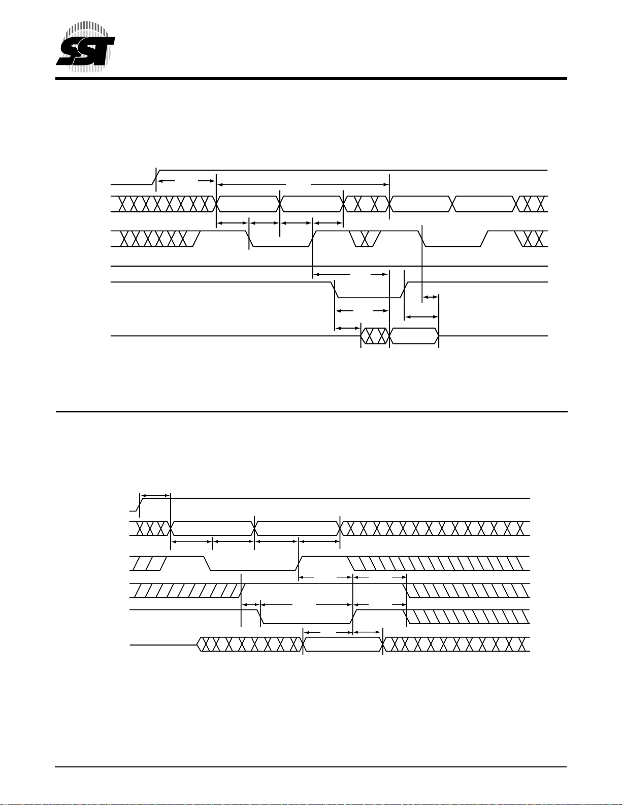
RST#
T
RST
Addresses
T
AS
T
R/C#
V
WE#
IH
OE#
DQ
7-0
F
IGURE 7: READ CYCLE TIMING DIAGRAM (PP MODE)
High-Z
AH
T
RC
T
OH
Column Address
High-Z
504 ILL F28.1
Row AddressColumn AddressRow Address
AS
T
AH
T
AA
T
OLZ
T
OE
T
OHZ
Data Valid
T
T
RST
RST#
Addresses
T
AS
T
AH
Column AddressRow Address
T
AS
T
AH
R/C#
OE#
T
OES
T
CWH
T
WP
T
OEH
T
WPH
WE#
T
DH
504 ILL F29.0
DQ
7-0
T
DS
Data Valid
FIGURE 8: WRITE CYCLE TIMING DIAGRAM (PP MODE)
© 2000 Silicon Storage Technology, Inc. 504-2 8/00
18
Page 19
2 Mbit / 4 Mbit Firmware Hub
SST49LF002A / SST49LF004A
Advance Information
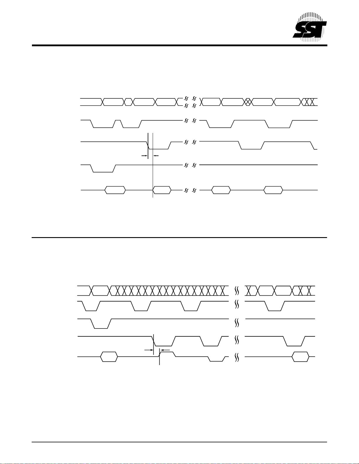
1
ADDRESS A
FIGURE 9: DATA# POLLING TIMING DIAGRAM (PP MODE)
18-0
R/C#
OE#
WE#
DQ
T
7
DD# D# D
2
3
4
OEP
5
6
504 ILL F30.0
7
8
9
Addresses
R/C#
WE#
OE#
T
OET
DQ
6
504 ILL F31.0
FIGURE 10: TOGGLE BIT TIMING DIAGRAM (PP MODE)
© 2000 Silicon Storage Technology, Inc. 504-2 8/00
19
10
11
12
13
14
15
16
Page 20
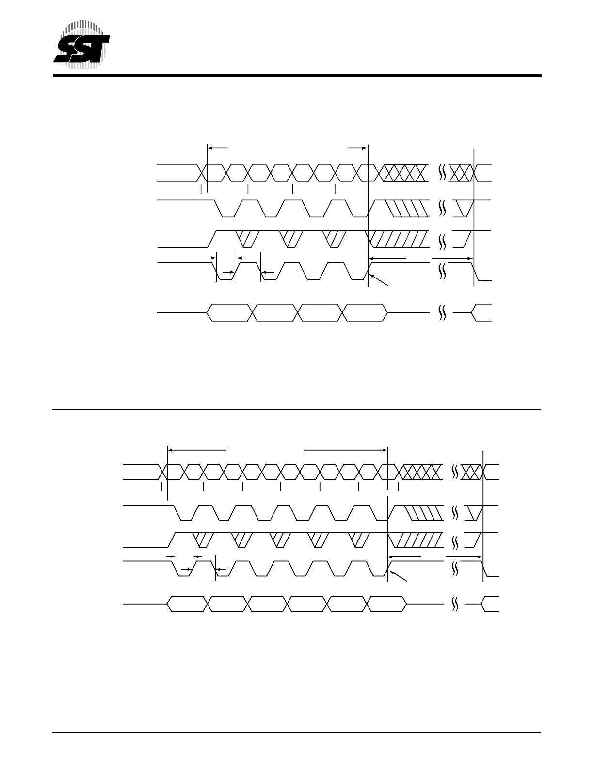
Addresses
R/C#
OE#
WE#
Four-Byte Code for Byte-Program
5555 2AAA 5555 BA
T
WP
T
WPH
SB0
SB1 SB2 SB3
2 Mbit / 4 Mbit Firmware Hub
SST49LF002A / SST49LF004A
Advance Information
T
BP
Internal Program Starts
DQ
7-0
BA = Byte-Program Address
FIGURE 11: BYTE-PROGRAM TIMING DIAGRAM (PP MODE)
Six-Byte code for
Sector-Erase Operation
Addresses
5555 2AAA 5555 5555 2AAA SA
R/C#
OE#
T
WP
DQ
WE#
7-0
SB0
T
WPH
SB1 SB2 SB3 SB4 SB5
Data55AA A0
x
55AA55AA 80 30
504 ILL F53.0
T
SE
Internal Erasure Srarts
SAx = Sector Address
504 ILL F32.0
FIGURE 12: SECTOR-ERASE TIMING DIAGRAM (PP MODE)
© 2000 Silicon Storage Technology, Inc. 504-2 8/00
20
Page 21
2 Mbit / 4 Mbit Firmware Hub
SST49LF002A / SST49LF004A
Advance Information
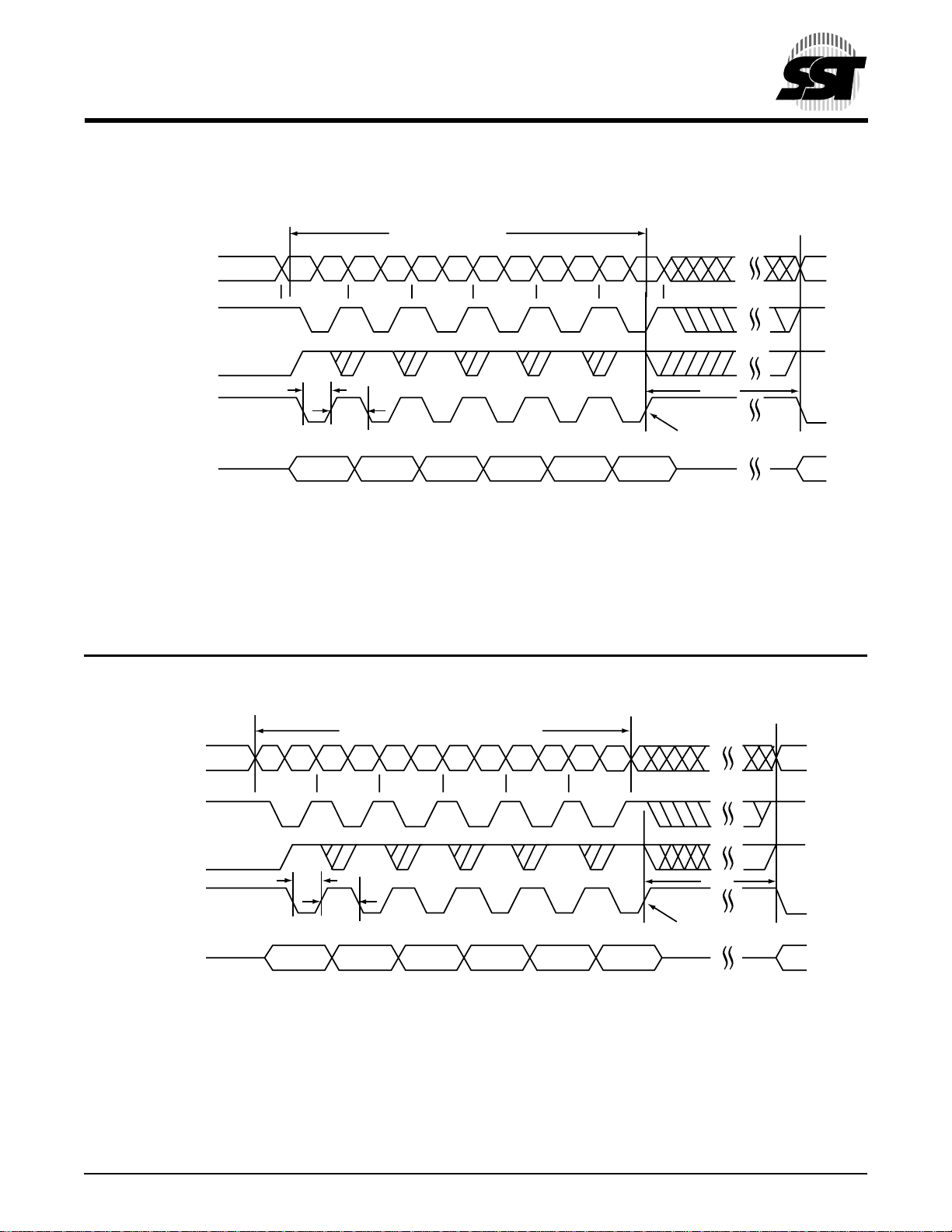
Six-Byte code for
Block-Erase Operation
Addresses
5555 2AAA 5555 5555 2AAA BA
R/C#
OE#
T
WP
DQ
WE#
7-0
BAx = Block Address
SB0
T
WPH
SB1 SB2 SB3 SB4 SB5
FIGURE 13: BLOCK-ERASE TIMING DIAGRAM (PP MODE)
x
55AA55AA 80 50
T
BE
Internal Erasure Srarts
504 ILL F48.0
1
2
3
4
5
6
7
8
Six-Byte code for Chip-Erase Operation
Addresses
5555 2AAA 5555 5555 2AAA 5555
R/C#
OE#
T
WP
DQ
WE#
7-0
T
WPH
SB0 SB1 SB2 SB3 SB4 SB5
FIGURE 14: CHIP-ERASE TIMING DIAGRAM (PP MODE)
55AA55AA 80 10
T
SCE
Internal Erasure Srarts
504 ILL F33.0
9
10
11
12
13
14
15
16
© 2000 Silicon Storage Technology, Inc. 504-2 8/00
21
Page 22
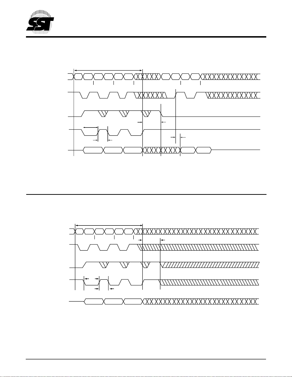
Three-byte sequence for
Software ID Entry
2 Mbit / 4 Mbit Firmware Hub
SST49LF002A / SST49LF004A
Advance Information
ADDRESS A
DQ
14-0
R/C#
OE#
WE#
7-0
5555 2AAA 5555 0000 0001
T
WP
T
WPH
55AA 90
SW0
Device ID = 57H for SST49LF002A, 60H for SST49LF004A
SW1 SW2
FIGURE 15: SOFTWARE ID ENTRY AND READ (PP MODE)
T
IDA
T
BF
AA
Device ID
504 ILL F34.1
Three-Byte Sequence for
Software ID Exit and Reset
ADDRESS A
DQ
14-0
R/C#
OE#
WE#
7-0
5555
2AAA 5555
T
WP
T
WHP
SW0 SW1 SW2
AA 55 F0
FIGURE 16: SOFTWARE ID EXIT AND RESET (PP MODE)
T
IDA
504 ILL F35.0
© 2000 Silicon Storage Technology, Inc. 504-2 8/00
22
Page 23
2 Mbit / 4 Mbit Firmware Hub
SST49LF002A / SST49LF004A
Advance Information
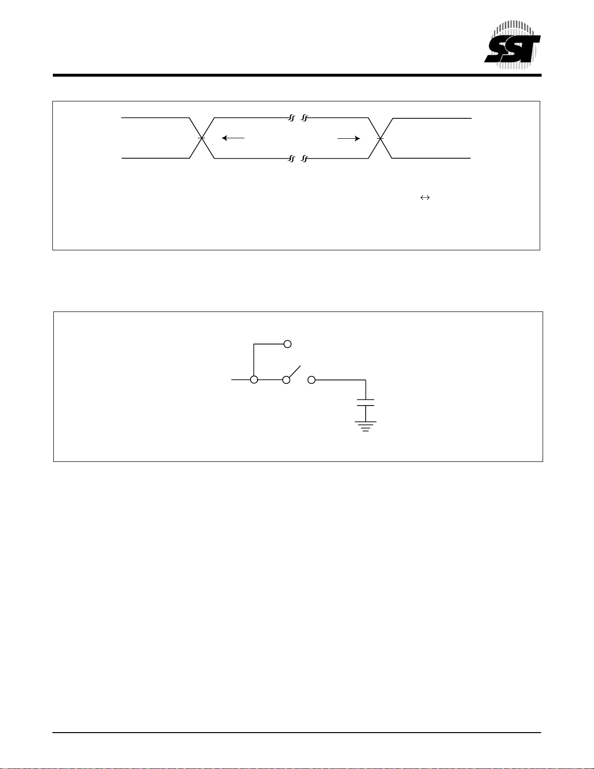
V
IHT
V
IT
V
ILT
AC test inputs are driven at V
for inputs and outputs are VIT (0.4 VDD) and V
FIGURE 17: AC INPUT/OUTPUT REFERENCE WAVEFORMS (PP MODE)
(0.9 VDD) for a logic “1” and V
IHT
TO DUT
504 ILL F07.0
REFERENCE POINTS OUTPUTINPUT
ILT
(0.4 VDD). Inputs rise and fall times (10% « 90%) are <3 ns.
IT
V
OT
504 ILL F06.1
(0.1 VDD) for a logic “0”. Measurement reference points
TO TESTER
Note: VIT–V
V
OT–VOUTPUT
V
IHT–VINPUT
V
ILT–VINPUT
C
L
INPUT
Test
Test
HIGH Test
LOW Test
1
2
3
4
5
6
7
8
9
FIGURE 18: A TEST LOAD EXAMPLE (PP MODE)
© 2000 Silicon Storage Technology, Inc. 504-2 8/00
23
10
11
12
13
14
15
16
Page 24
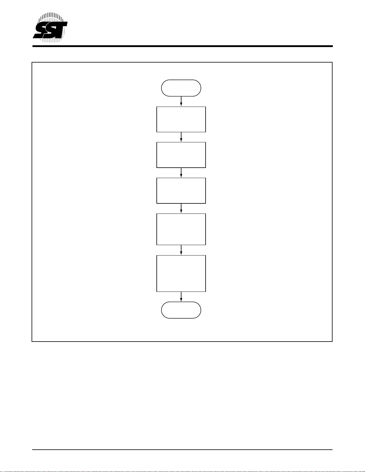
Start
Write data: AA
Address: 5555
Write data: 55
Address: 2AAA
Write data: A0
Address: 5555
2 Mbit / 4 Mbit Firmware Hub
SST49LF002A / SST49LF004A
Advance Information
F
IGURE 19: BYTE-PROGRAM ALGORITHM
Load Byte
Address/Byte
Data
Wait for end of
Program (TBP,
Data# Polling
bit, or Toggle bit
operation)
Program
Completed
504 ILL F36.0
© 2000 Silicon Storage Technology, Inc. 504-2 8/00
24
Page 25
2 Mbit / 4 Mbit Firmware Hub
SST49LF002A / SST49LF004A
Advance Information
1
Internal Timer
Byte-
Program/Erase
Initiated
Wait TBP,
T
SCE, TBE
or TSE
Program/Erase
Completed
Program/Erase
No
Toggle Bit
Byte-
Initiated
Read byte
Read same
byte
Does DQ
match?
6
Yes
No
Data# Polling
Byte-
Program/Erase
Initiated
Read DQ
Is DQ7 =
true data?
Program/Erase
Completed
7
Yes
2
3
4
5
6
7
8
9
FIGURE 20: WAIT OPTIONS
Program/Erase
Completed
10
504 ILL F37.0
11
12
13
14
15
16
© 2000 Silicon Storage Technology, Inc. 504-2 8/00
25
Page 26
2 Mbit / 4 Mbit Firmware Hub
SST49LF002A / SST49LF004A
Advance Information
Software Product ID Entry
Command Sequence
Write data: AA
Address: 5555
Write data: 55
Address: 2AAA
Write data: 90
Address: 5555
Wait T
IDA
Read Software ID
Software Product ID Exit &
Reset Command Sequence
Write data: AA
Address: 5555
Write data: 55
Address: 2AAA
Write data: F0
Address: 5555
Wait T
IDA
Return to normal
operation
Write data: F0
Address: XX
Wait T
IDA
Return to normal
operation
504 ILL F38.0
F
IGURE 21: SOFTWARE PRODUCT COMMAND FLOWCHARTS
© 2000 Silicon Storage Technology, Inc. 504-2 8/00
26
Page 27
2 Mbit / 4 Mbit Firmware Hub
SST49LF002A / SST49LF004A
Advance Information
Chip-Erase
Command Sequence
Write data: AA
Address: 5555
Write data: 55
Address: 2AAA
Write data: 80
Address: 5555
Write data: AA
Address: 5555
Write data: 55
Address: 2AAA
Block-Erase
Command Sequence
Write data: AA
Address: 5555
Write data: 55
Address: 2AAA
Write data: 80
Address: 5555
Write data: AA
Address: 5555
Write data: 55
Address: 2AAA
Sector-Erase
Command Sequence
Write data: AA
Address: 5555
Write data: 55
Address: 2AAA
Write data: 80
Address: 5555
Write data: AA
Address: 5555
Write data: 55
Address: 2AAA
1
2
3
4
5
6
7
8
9
Write data: 10
Address: 5555
Wait Options
Chip erased
to FFH
FIGURE 22: ERASE COMMAND SEQUENCE
© 2000 Silicon Storage Technology, Inc. 504-2 8/00
Write data: 50
Address: BA
Wait Options
Block erased
to FFH
27
X
Write data: 30
Address: SA
Wait Options
Sector erased
to FFH
504 ILL F39.0
X
10
11
12
13
14
15
16
Page 28
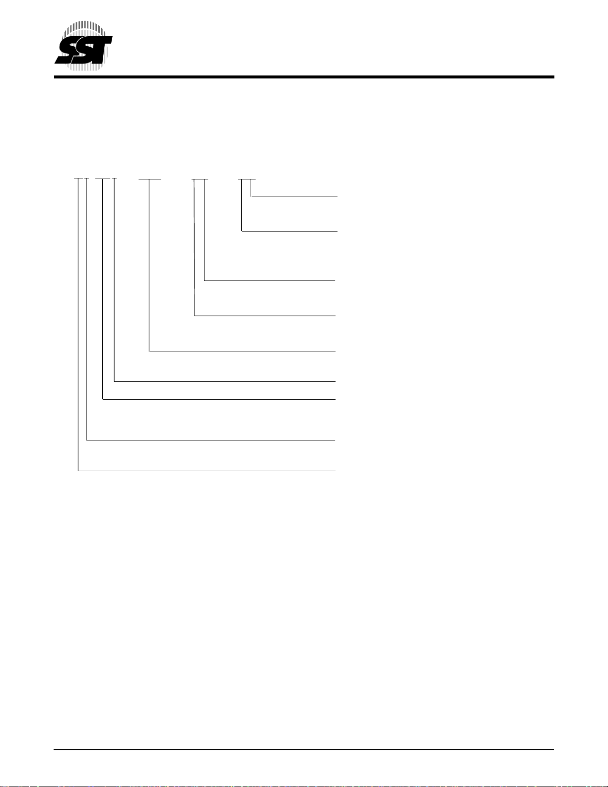
PRODUCT ORDERING INFORMATION
Device Speed Suffix1 Suffix2
SST49LF00xA - XXX - XX - XX
2 Mbit / 4 Mbit Firmware Hub
SST49LF002A / SST49LF004A
Advance Information
Package Modifier
H = 32 pins
Package Type
N = PLCC
W = TSOP (die up) (8mm x 14mm)
Operating Temperature
C = Commercial = 0° to 85°C
Minimum Endurance
4 = 10,000 cycles
Serial Access Clock Frequency
33 = 33 MHz
Version
Density
002 = 2 Mbits
004 = 4 Mbits
Voltage Range
L = 3.0-3.6V
Device Family
SST49LF002A Valid combinations
SST49LF002A-33-4C-WH SST49LF002A-33-4C-NH
SST49LF004A Valid combinations
SST49LF004A-33-4C-WH SST49LF004A-33-4C-NH
Example:Valid combinations are those products in mass production or will be in mass production. Consult your SST sales
representative to confirm availability of valid combinations and to determine availability of new combinations.
© 2000 Silicon Storage Technology, Inc. 504-2 8/00
28
Page 29
2 Mbit / 4 Mbit Firmware Hub
SST49LF002A / SST49LF004A
Advance Information
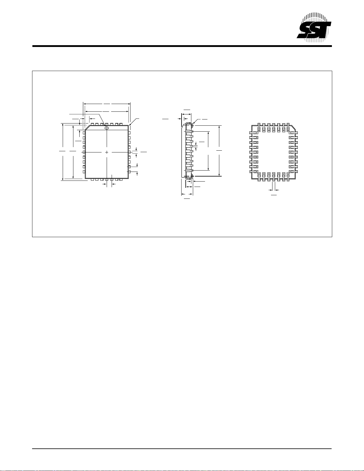
PACKAGING DIAGRAMS
TOP VIEW SIDE VIEW BOTTOM VIEW
.485
.495
Optional Pin #1
Identifier
.585
.595
.042
.048
.042
.048
.547
.553
Note: 1. Complies with JEDEC publication 95 MS-016 AE dimensions, although some dimensions may be more stringent.
.447
.453
1232
.050
BSC.
2. All linear dimensions are in inches (min/max).
3. Dimensions do not include mold flash. Maximum allowable mold flash is .008 inches.
.020 R.
MAX.
.026
.032
.050
BSC.
32-PIN PLASTIC LEAD CHIP CARRIER (PLCC)
SST PACKAGE CODE: NH
.023
.029
x 30˚
.106
.112
.125
.140
.075
.095
.013
.021
.030
.040
R.
.400
BSC
.015 Min.
.490
.530
.026
.032
32.PLCC.NH-ILL.1
1
2
3
4
5
6
7
8
9
© 2000 Silicon Storage Technology, Inc. 504-2 8/00
29
10
11
12
13
14
15
16
Page 30
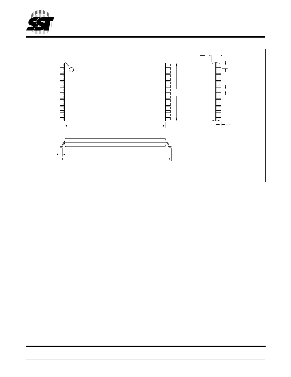
PIN # 1 IDENTIFIER
2 Mbit / 4 Mbit Firmware Hub
SST49LF002A / SST49LF004A
Advance Information
1.05
0.95
.50
BSC
12.50
12.30
0.70
0.50
Note: 1. Complies with JEDEC publication 95 MO-142 BA dimensions, although some dimensions may be more stringent.
2. All linear dimensions are in millimeters (min/max).
3. Coplanarity: 0.1 (±.05) mm.
14.20
13.80
32-PIN THIN SMALL OUTLINE PACKAGE (TSOP) 8MM X 14MM
SST PACKAGE CODE: WH
8.10
7.90
0.15
0.05
32.TSOP-WH-ILL.3
.270
.170
Silicon Storage Technology, Inc. • 1171 Sonora Court • Sunnyvale, CA 94086 • Telephone 408-735-9110 • Fax 408-735-9036
www.SuperFlash.com or www.ssti.com • Literature FaxBack 888-221-1178, International 732-544-2873
© 2000 Silicon Storage Technology, Inc. 504-2 8/00
30
 Loading...