

Page 1
ADVANCED DATA SHEET
42142
RADIATION TOLERANT
POWER OPERATIONAL AMPLIFIER
HYBRID MICROELECTRONICS
Mii
PRODUCTS DIVISION
Features:
Design Tested to 100 krad(Si) Total Dose
•
Hermetically Sealed in Metal Package
•
Performance over –55°C to +125°C
•
Wide Supply Voltage Range
•
High Output Current
•
•
Short Circuit Protection
DESCRIPTION
The 42142 is a power operational amplifier designed for military and space applications where radiation tolerance is
required. Utilizing multi-chip hybrid construction, the 42142 power operational amplifier combines 10A load current
capability with the convenience of a monolithic operational amplifier. Output current limiting is provided using
external resistors. The 42142 power operational amplifier is supplied in an 8-pin hermetic flat package. This design
has demonstrated it will function with minimal degradation after exposure to 100 krad(Si) total dose. This device is
available as COTS, or screened to MIL-PRF-38534, Table C-IX, Class H or custom screening. Lead options
support both through-hole and surface-mount assembly.
Applications:
Satellite/Space systems
•
Military/High Reliability Systems
•
Programmable Power Supplies
•
Solenoid Driver
•
Servo Motor Amplifier
•
Synchro Power Amplifier
•
ABSOLUTE MAXIMUM RATINGS:
Supply Voltage (±VS) ………………………………………………………………………………………………... ± 22 V
Input Voltage
Differential Input Voltage
Peak Output Current
(1)
……………………………………………………………………...………………………..….……. ± 22 V
(2)
……………………………………………….……...…………………………………. ± 0.7 V
(3)
…………………………………………………………………………………………………. 10 A
Storage Temperature Range …………………………………………………………………………..… -65°C to +150°C
Operating Junction Temperature ……………………………………………………………………..…. -55°C to +150°C
Lead Solder Temperature for 10 seconds ………………………………………………………….………….…….. 300°C
Power Dissipation
(4)
……………..……………………………………………………………………………….……. 95 W
Linear Derating Factor …………………………………………………………………………………..………... 0.76 W/°C
WEIGHT: ………………………………………………………………….…………… ……………….. 15.2 grams (typical)
RECOMMENDED OPERATING CONDITIONS:
Parameter Symbol Min. Max. Units
Supply Voltage ±V
Ambient Temperature T
S
A
820 VDC
-55 125 °C
Micropac Industries cannot assume any responsibility for any circuits shown or represent that they are free from patent infringement.
Micropac reserves the right to make changes at any time in order to improve design and to supply the best product possible.
MICROPAC INDUSTRIES, INC. HYBRID MICROELECTRONICS PRODUCTS DIVISION • 905 E. Walnut St., Garland, TX 75040 • (972) 272-3571 • Fax (972) 494-2281
www.micropac.com E-MAIL: hybridsales@micropac.com
05/17/01
Page 2
ADVANCED DATA SHEET 42142
Radiation Tolerant Power Operational Amplifier
ELECTRICAL SPECIFICATIONS (Pre-Irradiation)
VS = ± 15 V, TC = -55°C to +125°C unless otherwise specified
Parameter Symbol Min. Typ.* Max. Units Test Conditions
Input Offset Voltage V
Input Offset Voltage Drift
Input Bias Current I
B+, IB-
Input Offset Current I
DC Open Loop Gain A
Common-Mode Input Voltage
Range
OS
OS
VOL
V
CM
100 126
± 10.3 ± 12.3
Common-Mode Rejection Ratio CMRR 100
Gain Bandwidth Product
Phase Margin
(5)
(5)
GBW
Φ
M
Slew Rate SR 2
Output Voltage Swing V
Quiescent Current I
Thermal Resistance
O
Q
θ
JA
± 12
± 10
* All typical values are at TC = 25°C
± 25 ± 200
± 5
V/°C
µ
V
µ
± 15 ± 80 nA
10 75 nA
1
45
dB
V
dB
MHz
degree
V/µs
V
47mA
30
°C/W TO-3 package
R
> 2 kΩ, VO = ± 10V
L
= ± 9 VDC
V
CM
= 10 k
R
L
= 10 k
R
L
Ω
Ω
(small signal)
R
= 100
L
R
CL
RL = 10 k
R
= 1
L
R
= ∞
L
= 0
Ω
Ω
Ω
Ω
Ω
Notes:
1. For V
less than ± 22 V, the input voltage is not to exceed ± VS.
S
2. Input current must not exceed 25 mA
3. It is recommended that external current limiting resistors (± R
that 10 A is not exceeded. See Figures 1, 2 and 4 for R
4. Case Temperature T
= 25°C (see Figure 3).
C
CL
≥ 0.068 Ω) be used to ensure
CL
application information.
5. Guaranteed by design.
Micropac Industries cannot assume any responsibility for any circuits shown or represent that they are free from patent infringement.
Micropac reserves the right to make changes at any time in order to improve design and to supply the best product possible.
MICROPAC INDUSTRIES, INC. HYBRID MICROELECTRONICS PRODUCTS DIVISION • 905 E. Walnut St., Garland, TX 75040 • (972) 272-3571 • Fax (972) 494-2281
www.micropac.com E-MAIL: hybridsales@micropac.com
05/17/01
Page 3
ADVANCED DATA SHEET 42142
Radiation Tolerant Power Operational Amplifier
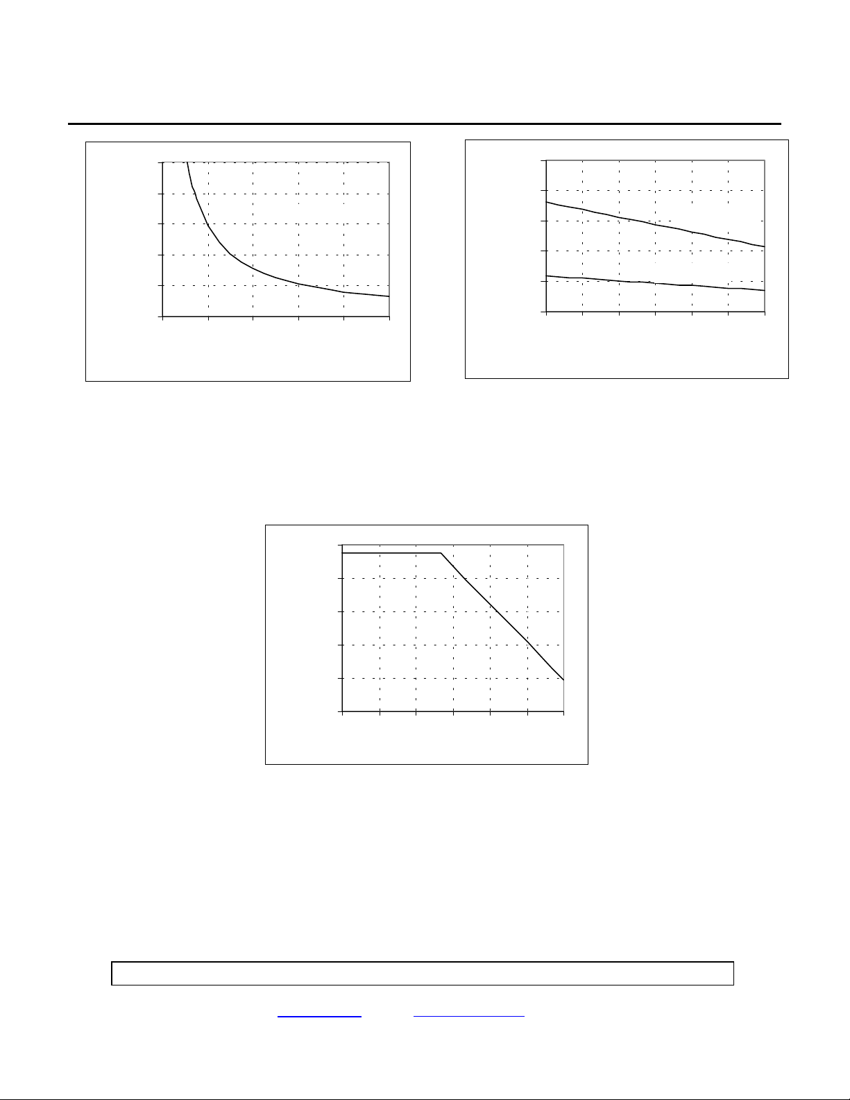
10
8
6
TC = 25°C
4
Current (±A)
2
Short-C ircuit Ou tput
0
0 0.1 0.2 0.3 0.4 0.5
Resistance (ohm)
10
8
6
RCL = .10 ohm
4
Current (±A)
2
Short-C ircuit Ou tput
RCL = .33 ohm
0
-55 -25 5 35 65 95 125
Temperature (°C)
Figure 1. Typical Short-Circuit Output Current Figure 2. Short-Circuit Output Current vs.
Case
vs. Current Limiting Resistors (±R
) Temperature (typical data).
CL
100
80
60
40
20
Internal Power Dissipation (W)
0
-55 -25 5 35 65 95 125
Temperature (°C)
Figure 3. Maximum Average Power Dissipation
vs. Case Temperature (TO-3 package)
Micropac Industries cannot assume any responsibility for any circuits shown or represent that they are free from patent infringement.
Micropac reserves the right to make changes at any time in order to improve design and to supply the best product possible.
MICROPAC INDUSTRIES, INC. HYBRID MICROELECTRONICS PRODUCTS DIVISION • 905 E. Walnut St., Garland, TX 75040 • (972) 272-3571 • Fax (972) 494-2281
www.micropac.com E-MAIL: hybridsales@micropac.com
05/17/01
Page 4

ADVANCED DATA SHEET 42142
Radiation Tolerant Power Operational Amplifier
+V
S
50 F
+R
CL
42142
3
2
1
8
6
-R
CL
4
5
SIGNAL
GROUND
LOAD
50 F
-V
S
Figure 4. Application Information
Controlling the short circuit current to the minimum necessary for a given application maximizes
device protection and reliability.
Approximate values for the current limiting resistors can be determined from the equation:
R
= (0.65/ISC - 0.01) Ω
CL
where I
is the short circuit current limit in amperes at TC = 25°C.
SC
Current limits for positive and negative load currents can be set independently.
Current limiting resistors carry the full output current, therefore the short circuit current limit should be
used in determining resistor wattage. Lead lengths of the limiting resistors should be minimized and
highly inductive resistor types should be avoided.
Large bypass capacitors (50 µF) are recommended across the power supply terminals if the application
requires large output current transients. Care should be taken to keep the power supply ground currents
from flowing through the signal ground path.
Micropac Industries cannot assume any responsibility for any circuits shown or represent that they are free from patent infringement.
Micropac reserves the right to make changes at any time in order to improve design and to supply the best product possible.
MICROPAC INDUSTRIES, INC. HYBRID MICROELECTRONICS PRODUCTS DIVISION • 905 E. Walnut St., Garland, TX 75040 • (972) 272-3571 • Fax (972) 494-2281
www.micropac.com E-MAIL: hybridsales@micropac.com
05/17/01
Page 5

ADVANCED DATA SHEET 42142
Radiation Tolerant Power Operational Amplifier
TOTAL DOSE TEST RESULTS
Disclaimer: The data of 4 representative units irradiated in Cobalt-60 chamber is only typical of one lot of
operational amplifiers. Micropac does not guarantee performance of its Operational Amplifier to these
radiation levels. Individual lots have to be screened to guarantee the performance.
40
V
30
µ
20
50
40
30
10
0
-10
Input Offset Voltage,
-20
050100
Total Dose, krad (Si)
20
10
Input Off set Current, nA
0
0 50 100
Total Dose, krad (Si)
Figure 5. Input Offset Voltage vs Total Dose Figure 6. Input Offset Current vs Total Dose
500
400
300
500
400
300
200
100
Input(+) Bias Current, nA
0
050100
Total Dose, krad (Si)
200
100
Input(-) Bias Current, nA
0
0 50 100
Total Dose, krad (Si)
Figure 7. Input (+) Bias Current vs Total Dose Figure 8. Input (-) Bias Current vs Total Dose
Micropac Industries cannot assume any responsibility for any circuits shown or represent that they are free from patent infringement.
Micropac reserves the right to make changes at any time in order to improve design and to supply the best product possible.
MICROPAC INDUSTRIES, INC. HYBRID MICROELECTRONICS PRODUCTS DIVISION • 905 E. Walnut St., Garland, TX 75040 • (972) 272-3571 • Fax (972) 494-2281
www.micropac.com E-MAIL: hybridsales@micropac.com
05/17/01
Page 6

ADVANCED DATA SHEET 42142
Radiation Tolerant Power Operational Amplifier
132
5
130
4
128
Quiescent Current, mA
Open Loop Volage Gain, dB
126
050100
Total Dose, krad (Si)
3
050100
Total Dose, krad (Si)
Figure 9. Open Loop Voltage Gain vs Total Dose Figure 10. Quiescent Current vs Total Dose
Micropac Industries cannot assume any responsibility for any circuits shown or represent that they are free from patent infringement.
Micropac reserves the right to make changes at any time in order to improve design and to supply the best product possible.
MICROPAC INDUSTRIES, INC. HYBRID MICROELECTRONICS PRODUCTS DIVISION • 905 E. Walnut St., Garland, TX 75040 • (972) 272-3571 • Fax (972) 494-2281
www.micropac.com E-MAIL: hybridsales@micropac.com
05/17/01
Page 7

ADVANCED DATA SHEET 42142
Radiation Tolerant Power Operational Amplifier
CASE OUTLINE
NOTE: Dimensions in inches.
ELECTRICAL CONNECTIONS
Pin 1 ................................................+V
Pin 2 ................................................ -IN
Pin 3 ................................................ +IN
Pin 4 ................................................ -V
Pin 5 ................................................ CL-
Pin 6 ............................................... OUT
Pin 7 ................................................ NC
Pin 8 ................................................ CL+
Micropac Industries cannot assume any responsibility for any circuits shown or represent that they are free from patent infringement.
Micropac reserves the right to make changes at any time in order to improve design and to supply the best product possible.
MICROPAC INDUSTRIES, INC. HYBRID MICROELECTRONICS PRODUCTS DIVISION • 905 E. Walnut St., Garland, TX 75040 • (972) 272-3571 • Fax (972) 494-2281
www.micropac.com E-MAIL: hybridsales@micropac.com
s
s
05/17/01
Page 8

ADVANCED DATA SHEET 42142
Radiation Tolerant Power Operational Amplifier
CASE OUTLINE (FOR ENGINEERING SAMPLES ONLY)
A
DIM
A
B
C
D
E
F
G
H
J
K
Q
R
MILLIMETERS
MIN
38.351.5501.510
MAXMIN MAX
39.37
.745
INCHES
.770 18.92 19.56
.260 .300 6.60 7.62
.038 .042 0.97 1.07
.080 .105 2.03 2.67
40° BASIC40° BASIC
.500 BASIC 12.7 BASIC
30.12 BASIC1.186 BASIC
.583 BASIC
15.08 BASIC
.500.400 10.16 12.70
.151 .161 3.84 4.09
.980 1.020 24.89 25.91
SEATING
PLANE
Q
B
E
D
H
G
F
J
2
3
1
4
5
8
6
7
C
K
NOTE: Leads in true position with 0.010" (0.25mm) R at
MMC at seating plane.
Pin numbers shown for refence only. Numbers may
not be marked on package.
ELECTRICAL CONNECTIONS
Pin 1 ........................................... Output
Pin 2 ............................................... CL+
Pin 3 ............................................... +V
Pin 4 ............................................... +IN
Pin 5 ................................................ -IN
Pin 6 ............................................... -V
Pin 7 ............................................... N.C.
Pin 8 ................................................ CL-
NOTE: The engineering samples could be provided in TO-3 package with the pin functions as shown above.
s
s
Micropac Industries cannot assume any responsibility for any circuits shown or represent that they are free from patent infringement.
Micropac reserves the right to make changes at any time in order to improve design and to supply the best product possible.
MICROPAC INDUSTRIES, INC. HYBRID MICROELECTRONICS PRODUCTS DIVISION • 905 E. Walnut St., Garland, TX 75040 • (972) 272-3571 • Fax (972) 494-2281
www.micropac.com E-MAIL: hybridsales@micropac.com
05/17/01
 Loading...